P1200 产品使用手册
- 格式:ppt
- 大小:5.84 MB
- 文档页数:32

胖瘦一体A P用户手册REV1.7.01910040639声明Copyright © 2016 普联技术有限公司版权所有,保留所有权利未经普联技术有限公司明确书面许可,任何单位或个人不得擅自仿制、复制、誊抄或转译本手册部分或全部内容,且不得以营利为目的进行任何方式(电子、影印、录制等)的传播。
为普联技术有限公司注册商标。
本手册提及的所有商标,由各自所有人拥有。
本手册所提到的产品规格和资讯仅供参考,如有内容更新,恕不另行通知。
除非有特殊约定,本手册仅作为使用指导,所作陈述均不构成任何形式的担保。
前言本手册旨在帮助您正确使用胖瘦一体AP产品。
内容包含对胖瘦一体AP产品性能特征的描述以及配置胖瘦一体AP产品的详细说明。
请在操作前仔细阅读本手册。
目标读者本手册的目标读者为熟悉网络基础知识、了解网络术语的技术人员。
本书约定正文中出现的符号约定特殊图标约定其他约定在本手册中,所提到的“AP”、“本产品”等名词,如无特别说明,系指胖瘦一体AP产品。
全文如无特殊说明,Web界面以TL-AP600C-PoE机型为例。
目录1 产品介绍 .....................................................................................................................................1-11.1 无线吸顶式AP .........................................................................................................................1-11.2 无线桌面式AP .........................................................................................................................1-21.3 无线面板式AP .........................................................................................................................1-21.4 室外高功率无线AP ..................................................................................................................1-32 工作模式 .....................................................................................................................................2-12.1 FAT AP模式 .............................................................................................................................2-12.1.1 首页 ..............................................................................................................................2-1设备信息 .......................................................................................................................2-2无线参数 .......................................................................................................................2-2无线服务 .......................................................................................................................2-2无线客户端 ...................................................................................................................2-22.1.2 无线 ..............................................................................................................................2-3无线服务 .......................................................................................................................2-3WDS设置 .....................................................................................................................2-8高级设置 .....................................................................................................................2-10频谱导航 .....................................................................................................................2-112.1.3 安全 ............................................................................................................................2-12无线MAC地址过滤 ....................................................................................................2-12VLAN设置 ..................................................................................................................2-132.1.4 系统 ............................................................................................................................2-14设备管理 .....................................................................................................................2-15管理账号 .....................................................................................................................2-15系统日志 .....................................................................................................................2-16时间设置 .....................................................................................................................2-17配置管理 .....................................................................................................................2-17软件升级 .....................................................................................................................2-18Ping看门狗 ................................................................................................................2-192.2 FIT AP模式 ............................................................................................................................2-19附录A 规格参数 ...............................................................................................................................A-1 TL-AP1750C-PoE ......................................................................................................A-1TL-AP1200C-PoE ......................................................................................................A-2TL-AP902C-PoE ........................................................................................................A-3TL-AP900C-PoE ........................................................................................................A-4TL-AP600C-PoE ........................................................................................................A-5TL-AP453C-PoE ........................................................................................................A-6TL-AP452C-PoE ........................................................................................................A-7TL-AP450C-PoE ........................................................................................................A-8TL-AP303C-PoE ........................................................................................................A-9TL-AP302C-PoE ......................................................................................................A-10TL-AP300C-PoE ......................................................................................................A-11TL-AP901C ...............................................................................................................A-12TL-AP451C ...............................................................................................................A-13TL-AP301C ...............................................................................................................A-14TL-AP450D ...............................................................................................................A-15TL-AP300D ...............................................................................................................A-16TL-AP450I-DC .........................................................................................................A-17TL-AP302I-DC .........................................................................................................A-18TL-AP300I-DC .........................................................................................................A-19TL-AP450I-PoE ........................................................................................................A-20TL-AP306I-PoE ........................................................................................................A-21TL-AP303I-PoE ........................................................................................................A-22TL-AP302I-PoE ........................................................................................................A-23TL-AP300I-PoE ........................................................................................................A-24TL-AP300P ...............................................................................................................A-251 产品介绍TP-LINK胖瘦一体AP产品均采用胖瘦一体工作模式,在胖AP(FAT AP)模式下,AP可单独使用,为无线客户端提供无线服务;在瘦AP(FIT AP)模式下,AP由TP-LINK无线控制器统一管理,即插即用。

150A/1200V IPM 数据手册PM150RLA120控制端口定义:1:V UPC (U 组电源地) 2:U FO (U 组故障输出) 3:U P (U 组信号输入) 4:V UP1(U 组驱动电源正极) 5:V VPC (V 组电源地) 6:V FO (V 组故障输出) 7:V P (V 组信号输入) 8:V VP1(V 组驱动电源正极) 9:V WPC (W 组电源地) 10:W FO (W 组故障输出) 11:W P (W 组信号输入) 12:W VP1(W 组电源正极)13:V NC (下桥臂驱动电源共地) 14: V N1(下桥W 组信号输入) 15:Br (制动单元信号输入) 16:U N (下桥U 组信号输入) 17:V N (下桥V 组信号输入) 18:W N (下桥臂驱动电源正极)19:F O (下桥臂故障输出)封装尺寸:(单位:mm )控制端采用镀金工艺A :135 L: 40.5 W: M5 AG: 10.5B :110 M: 20.0 X: dia.5.5 AH:21.5C :110 N: 16.5 Y: Rad.6D :78 P: 11.0Z: 10.0 E :71.5 Q: 30.15AA: 3.25 F :66.5 R: 11.0 AB: 2.0 G :34.7 S: 13.0 AC: 6.05 H :33.6 T: 4.0 AD: 18.0 J :24.1 U: dia.2.5 AE: 11.7 K: 26.0V: sq.0.5AF: 18.7产品概述:该款智能功率模块采用绝缘基板工艺,内置优化后的栅级驱动和保护电路,非常适合用于频率高达20KHZ功率变换场合。
产品特点:z完整的功率输出电路,直接连接负载。
z内置栅极驱动电路。
z保护电路:-短路保护;-过温保护,内置温度探头。
-驱动电压欠压保护。
z采用第五代低功耗IGBT管芯。
z30KW电机适用应用领域:z UPSz变频器z电机/司服控制z变频电源最大额定值:定义对象符号最大额定值单位功率器件的结温Tj -20—150 ℃储存温度Tstg -40-125 ℃环境温度Tc -20-100 ℃直流母线电压(P-N 端电压) Vcc 1000 V 过压保护值Vcc(prot) 800 V 绝缘耐压Viso2500 V 绝缘耐压Viso2500 V IGBT 变频侧集电极-发射极电压Vces 1200 V 集电极电流(Tc=25)±Ic 150 A 集电极峰值电流(Tc=25)±Icp 300 A 集电极功耗(Tc=25)Pc 801 W IGBT 制动侧集电极-发射极电压Vces 1200 V 集电极电流(Tc=25)±Ic 75 A 集电极峰值电流(Tc=25)±Icp 150 A 集电极功耗(Tc=25)Pc 457 W 二极管正向电流If 75 A 控制侧驱动电压V D 20 V 输入信号电压V CIN 20 V 故障输出信号电压V FO 20 V 故障输出信号电流I FO 20 mA机械和电气特性:定义对象符号测试条件最小值典型值最大值单位IGBT变频侧V CE=V CES,V D=15V,Tj=25℃-- 1.0 mA 集电极-发射极关断电流IcesV CE=V CES,V D=15V,Tj=125℃-- 10 mA 二极管正向电压V EC Ic=25A,Vcin=15V,VD=15V - 2.5 3.5 VV D=15V,V CIN=0V,Ic=25A,Tj=25℃- 1.8 2.3 V 饱和压降VsatV D=15V,V CIN=0V,Ic=25A,Tj=125℃- 1.9 2.4 VTon0.5 1.0 2.5 μstrr VD=15V,VCIN=0-15V,Ic=25A,Tj=125℃- 0.5 0.8 μstc(on)Vcc=600V - 0.4 1.0 μstoff - 2.0 3.0 μs 开关时间tc off - 0.7 1.2 μs IGBT制动侧-- 1.0 mA 集电极-发射极关断电流Ices V CE=V CES,V D=15V,Tj=25℃V CE=V CES,V D=15V,Tj=125℃-- 10 mA 二极管正向电压V FM IF=15A - 2.5 3.5 VVsat V D=15V,V CIN=0V,Ic=25A,Tj=25℃- 1.8 2.3 V 饱和压降t)V D=15V,V CIN=0V,Ic=25A,Tj=125℃- 1.9 2.4 V 控制侧短路电流变频侧200 -- ASC 制动侧100 -- A 短路延时T SC VD=15V - 0.2 -μsOT 触发式测试135 145 155 ℃过温保护OTR 过热复位-125 -℃U V触发式测试11.5 12 12.5 V 驱动电压欠压保护UVR 欠压复位-12.5 -VV D=15V,V CIN=15V,W N-V NC(下三桥总耗电流)- 24 34 mA 驱动电流I DV D=15V,V CIN=15V,(上桥每组耗用电流)- 10 15 mA 输入“打开”阈值V on 1.2 1.5 1.8 mA 输入“关闭”阈值V off 加在输入信号端与地之间的电压 1.7 2.0 2.3 mAIfo H V D=15V,V CIN=15V - - 0.01 mA 故障输出电流IfoLV D=15V,V CIN=15V - 10 15 mA 故障输出脉宽 tfo VD=15V 1.0 1.8 - mS 热阻特性变频部分瞬态热组Rth 每只IGBT部分- - 0.21 C/WRth 续流二极管部分- - 0.34 C/WRth IGBT部分- - 0.34 C/W 制动部分瞬态热阻Rth 续流二极管部分- - 0.52 C/W 连接热阻 Rth 基板温度到结温- - 0.023 C/W 推荐工作参数直流母线电压V cc加在P-N之间的电压< 800V 驱动电压V D加在驱动电源侧13.5 15.0 16.5 V 输入“开”电压V CIN加在信号输入端≤ 0.8 V 输入“关”电压Vcin 加在信号输入端≥ 9.0 V 载波频率fpwm 输入信号的频率≤ 20 KHZ 死区时间 Td 防止上下臂直接短路≥ 2.5 us 接口参考:1.为了系统稳定安全,建议使用光耦隔离方式;2.电源是整个变频系统的心脏,所以建议使用4组隔离电源供给IPM使用;3.吸收电容是消除DV/DT浪涌电压的关键元件,建议使用有效突波专用吸收电容;4.主电路的滤波电容是整个变频器的容量储存介质,建议使用等容量电解并联使用。
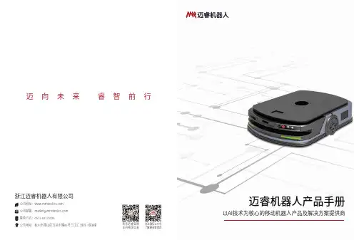
关注微信公众号了解更多新资讯浏览迈睿官网访问相关信息浙江迈睿机器人有限公司公司网址: 公司邮箱:*********************联系方式:*************公司地址: 杭州市萧山区万达中路95号三江汇.创谷 F区8幢迈向未来 睿智前行迈睿机器人产品手册以AI技术为核心的移动机器人产品及解决方案提供商CONTENTS目录011.1 关于我们021.2 荣誉资质032.1 机器人本体2.2 软件平台04053.1 智能搬运解决方案3.2 智能仓储解决方案06104.1 潜伏系列机器人4.2 叉取系列机器人4.3 移载系列机器人1416185.1 机器人调度系统5.2 智能仓储管理系统20 6.1 项目案例24220203关于我们 / 荣誉资质浙江迈睿机器人有限公司(简称“迈睿机器人”)是一家以AI技术为核心的移动机器人产品及解决方案提供商。
公司依托AI技术,结合机器人制造研发,为各行业客户提供完整的AI机器人+产品和解决方案,促进企业智能化升级。
公司始终专注于移动机器人产品研发,研发人员占比达80%,其中博士专家占比10%,聚集了一批高素质、高技术的专业型人才。
目前,公司机器人产品涵盖潜伏系列、叉取系列、移载系列等全系列智能移动机器人,提供由智能移动机器人和软件系统(机器人调度系统RCS、智能仓储管理系统iWMS、智能仓储控制系统WCS等)组成的智能仓储、智能搬运等智能化解决方案,并已在汽车、3C、物流、电商、光伏、锂电、医药、烟草、食品饮料、包装等行业及场景落地应用。
未来,公司将不断加大移动机器人技术及产品研发投入,为全球客户提供更智能化的移动机器人产品及解决方案,加速行业机器人换人进程。
公司定位以AI技术为核心的移动机器人产品及解决方案提供商公司愿景AI助力机器人换人公司实力TARGETINTEGRATIVEABILITY80%+研发人员占比10%+博士专家占比150项+公司专利项20+软件著作COMPANY公司简介CERTIFICATE证书奖项/ QUALIFICATION荣誉资质关于我们/ ABOUT US0405产品介绍 / 机器人本体 / 软件平台迈睿软件系统包括机器人调度系统RCS和智能仓储管理系统iWMS,它们在智能物流体系中扮演着非常重要的角色,是智能仓储设备控制中心、调度中心和任务管理中心。
SITOP 电源选择模块设备手册SITOP select6EP1961-2BA00 SITOP PSE200U 3A 6EP1961-2BA11 SITOP PSE200U 10 A 6EP1961-2BA21 SITOP PSE200U 3 A 6EP1961-2BA31 SITOP PSE200U 10 A 6EP1961-2BA41 概述安全提示 1 说明、设备结构、尺寸图 2 安装/拆卸 3 安装位置,安装距离 4 安装 5 技术数据 6 安全、认证、EMC 7 环境条件8 环保9 服务与支持10Siemens AGDivision Process Industries and Drives Postfach 48 4890026 NÜRNBERG C98130-A7579-A1-1-5D29Ⓟ 01/2015 本公司保留更改的权利Copyright © Siemens AG 2014.保留所有权利法律资讯警告提示系统为了您的人身安全以及避免财产损失,必须注意本手册中的提示。
人身安全的提示用一个警告三角表示,仅与财产损失有关的提示不带警告三角。
警告提示根据危险等级由高到低如下表示。
危险表示如果不采取相应的小心措施,将会导致死亡或者严重的人身伤害。
警告表示如果不采取相应的小心措施,可能导致死亡或者严重的人身伤害。
小心表示如果不采取相应的小心措施,可能导致轻微的人身伤害。
注意表示如果不采取相应的小心措施,可能导致财产损失。
当出现多个危险等级的情况下,每次总是使用最高等级的警告提示。
如果在某个警告提示中带有警告可能导致人身伤害的警告三角,则可能在该警告提示中另外还附带有可能导致财产损失的警告。
合格的专业人员本文件所属的产品/系统只允许由符合各项工作要求的合格人员进行操作。
其操作必须遵照各自附带的文件说明,特别是其中的安全及警告提示。
由于具备相关培训及经验,合格人员可以察觉本产品/系统的风险,并避免可能的危险。
1. Do not install this equipment in a confined or building-in space such as a book case or similar unit, and remain a well ventilation conditions at open site. The ventilation should not be impeded by covering the ventilation openings with items such as newspaper, table-cloths, curtains etc.2. No naked flame sources, such as lighted candles, should be placed on the apparatus.3. The product is designed to use in moderate climates4. Voltage selector: Used to adjust the input rating (110-120 Vac/60 Hz and 220-240 Vac/50 Hz), please just insert the mains power plug into the socket-outlet with voltage within the setting of the selector. The current ratings of mains fuse links are different for different input rating (see marking for details), and the fitted mains fuse link was just related to the input rating as setting of the selector during factory assembly line work, please ask a qualified personnel to help you replace the mains fuse link before you adjust the voltage selector.5. Protective earthing terminal. The apparatus should be connected to a mains socket outlet with a protective earthing connection. In Denmark: “Apparatets stikprop skal tilsluttes en stikkontakt med jord, som giver forbindelse til stikproppens jord.” In Finland: "Laite on liitettävä suojakoskettimilla varustettuun pistorasiaan" In Norway: “Apparatet må tilkoples jordet stikkontakt” In Sweden: “Apparaten skall anslutas till jordat uttag”IMPORTANT SAFETY INSTRUCTIONSWARNING1. Only use attachments/accessories specified or provided by the manufacturer.2. To reduce the risk of fire or electric shock, do not expose this apparatus to rain or moisture.The apparatus shall not be exposed to dripping or splashing and that objects filled with liquids, such as vases, shall not be placed on apparatus.3. The mains plug is used as disconnect device, the disconnect device shall remain readily operable.TABLE OF CONTENTS....................................................................................................................................................................................1 ................................................................................................................2 3 4 ............................................................................5 ...................................................................................5 6 ..................................................................................................................................................................7 ..................................................................................................................................................7 ...........................................................................................7 ......................................................................................................7 ..................................................................................7 .....................................................................................................7 ...........................................................................................7 ..................................................................................................................7INCLUDED ITEMS ATTACHING THE GRILLE SUBWOOFER REAR-PANEL CONTROLS AND CONNECTION ...........................................PLACING THE SUBWOOFER MAKING CONNECTIONS CONNECTING TO A STEREO RECEIVER, AMPLIFIER OR PREAMPLIFIER ...................SPECIFICATIONS OPERATING THE SUBWOOFER TURNING THE SUBWOOFER ON AND OFFSUBWOOFER ADJUSTMENTS: CROSSOVER SUBWOOFER ADJUSTMENTS: VOLUMESUBWOOFER ADJUSTMENTS: PHASEABNORMAL CONDITION :LED flashing USING THE SUPPLIED CARPET SPIKESCONNECTING THE SUBWOOFER TO A TRIGGER VOLTAGE SOURCE ...................................INCLUDED ITEMSYour new JBL ® powered subwoofer incorporates a high-performance transducer and built-in amplifier that delivers the powerful, dynamic and accurate low-frequency performance that makes your filmsoundtracks and music come alive. And with adjustable crossover, phase controls and automatic turn on/off, it is also simple to connect and set up.We’re confident that this JBL subwoofer will provide every note of enjoyment that you expect – and that when you think about purchasing additional audio equipment for your home, car or office, you will once again choose JBL products.This quick-start guide contains all the information you need to set up, connect and adjust your new subwoofer. For morein-depth information, go to our web site:.Powered SubwooferTHANK YOU FOR CHOOSING THIS JBL ® PRODUCTHDI-1200P4X Note: Type of power plug varies by regions.1X1X1One combination LFE and trigger cableE n g l i s hSUBWOOFER REAR-PANEL CONTROLS AND CONNECTION1)Power Mode :When switched to 'Auto' position, the subwoofer will then be in Standby mode. It will automatically turn on when an audio signal is detected and will return to the Standby mode when no audio signal is detected after approximately 10 minutes. Setting this switch to ‘On’ keeps the subwoofer powered until Power Switch is turned 'Off.'2)On/Standby LED:When the Power Switch is in the ‘On’ position, this LED indicates whether the subwoofer is in the On or Standby state.••When the LED glows red, the subwoofer is in the Standby mode.4)Low Pass Crossover:This control determines the highest frequency at which the subwoofer reproduces sounds. The higher you set the Crossover control, the higher in frequency the subwoofer will operate and the more its bass will“overlap” that of the speakers. This adjustment helps achieve a smooth transition of bass frequencies between the subwoofer and the speakers for a variety of different rooms and subwoofer locations.5) Subwoofer Gain:Use this control to adjust the subwoofer’s volume. Turn the knobclockwise to increase the volume; turn the knob counterclock-wise to decrease the volume.6)Input Connectors:Connect these to the outputs of a stereo preamp or connect a surround processor's subwoofer output to either the left or right input. Balanced (XLR) and unbalanced (RCA) connectors are available. The inputs are 0dBV nominal to +12dBV max unbal/+18dBV max bal. The XLR input is pin 2 hot.7)Power Switch:Set this switch in the ‘On’ position to turn the subwoofer on. If you willbe away from home, or will not be using the subwoofer for an extended period, set this switch in the ‘Off’ position to conserve energy.8)Power Cord Connector:After you have made and verified the subwoofer’s input connection,plug the power cord into an active, unswitched electrical outlet for proper operation of the subwoofer.DO NOT plug the power cord into the accessory outlets found on someaudio components.3)Phase Switch:This switch determines whether the subwoofer transducer’s piston-like action moves in and out in phase with the main speakers. If thesubwoofer were to play out of phase with the main speakers, the sound waves from the main speakers could partially cancel out the sound waves from the subwoofer, reducing bass performance and sonic impact. This phenomenon depends in part on the placement of all the speakers relative to the listening position and to each other in the room.9) 12V Trigger In/Out connectors:When the subwoofer’s Power Mode Switch is set to “Trigger”, the subwoofer will automatically turn on when 5V-12V is present at the 12V Trigger “in-connection”, and will turn off when the voltage at this connection is removed. Whenever the subwoofer in on, a 12V trigger signal is available at it’s 12V Trigger Out connector. It is for use with additional HDI-1200P subwoofers, or another triggerable device.11) EQ Frequency control:Selects the center frequency of the particular problem area. The range is from 32HZ to100Hz.12) EQ Bandwidth control:Sets the range of frequencies over which the equalizer will have an effect. The range is from 0.1 octaves to 0.6 octaves; the higher the number the broader the range of frequencies that will be affected.13) EQ Level control:Allows you to adjust how much boost or cut is applied to the selected frequency by the EQ Frequency Control. This control adjusts from-12dB to a maximum of +3dB.14) EQ On/Off switch:Enables/Disables the parmetric EQ controls (Frequency, Bandwidth, and EQ Level, but not Phase)81,3412111056910) Parametric Equalization (PEQ) controls:This set of equalization controls adjust for the dominant room mode at yourlistening position in your specific listening room. The parametric equalizer includes variable controls to adjust Frequency, Bandwidth, and EQ Level of one band of frequencies. To use these controls, you must first set the EQ switch to “ON”. NOTE: Specific measurement equipment is required to properly adjust the Equalization controls. Your authorized JBL dealer can make the appropriate measurements, using suitable equipment to ensure optimal results.3When the LED glows green , the subwoofer is turned On.CONNECTING THE SUBWOOFER TO A TRIGGER VOLTAGE SOURCE12VTRIGGEROUTPUTThe subwoofer will automatically turn on if it receives a trigger voltage at its External Trigger Input connector and will enter the Standby mode when the voltage ceases.If your preamp/processor or another audio/video component has a trigger-voltage connection that supplies between 3V and 30V (AC or DC), connect it to subwoofer’s Exteranl Trigger Input connector. If the component’s trigger-voltage connection has a 3.5mm mini jack, you can use the supplied combination LFE/trigger cable to make the connection.NOTE: Do not connect the subwoofer’s External Trigger input connector to a remote control output (IR Out) of your home cinema system or surround receiver. Doing so could lead to malfunction.4PLACING THE SUBWOOFERThe performance of a subwoofer is directly related to its placement in the listening room and its physical position relative to the other speakers in the system.While it is true that in general our ears do not hear directional sounds at the lowfrequencies where subwoofers operate, when installing a subwoofer within the limited confines of a room, the reflections, standing waves and absorptions generated within the room will strongly influence the performance of any subwoofer system. As a result, the specific location of the subwoofer in the room does become important to the amount and quality of bass that is produced.For example, placing the subwoofer next to a wall generally will increase the amount of bass in the room; placing it in a corner (1) generally will maximize amount of bass in the room. However, corner placement can also increase the destructive effect of standing waves on bass performance. This effect can vary depending on the listening position – some listening positions may yield very good results while others may have far too much (or too little) bass at certain frequencies.In many rooms, placing the subwoofer along the same plane as the left and rightspeakers (2) can produce the best integration between the sound of the subwoofer and that of the left and right speakers. In some rooms, the best performance could even result from placing the subwoofer behind the listening position (3).We strongly recommend that you experiment with placement before choosing a final location for your subwoofer. One way you can determine the best location for the subwoofer is by temporarily placing it in the listening position and playing music with strong bass content. Move around to various locations in the room while the system is playing (putting your ears where the subwoofer would be placed), and listen until you find the location where the bass performance is best. Place the subwoofer in that location.MAKING CONNECTIONSCAUTION: Never make or break connections unless all system components are powered off.5CONNECTING TO A STEREO RECEIVER,AMPLIFIER OR PREAMPLIFIERIf you are connecting to a stereo device, connect the subwoofer asshown below. Stereo components rarely have subwoofer outputs. Usethem if they are available; otherwise, be sure to use a Y-connector for theleft output and one for the right output, connecting the subwoofer input toone side of each Y and the input for the left or right or right main speaker amplifierto the other side of the Y for proper main speaker operation. You can make either balanced (XLR) or unbalanced (RCA) connections between the device and the subwoofer.Using this connection method, you must set the Low Pass Crossoverknob to some frequency between 50-150Hz, NOT on the “LFE”setting.6TURNING THE SUBWOOFER ON AND OFFSet the subwoofer’s Power Switch to the ‘On’ position. Now set the subwoofer’s Power Mode to the ‘Auto’ position. The subwoofer willautomatically turn itself on when it receives an audio signal, and it will go into Standby mode after it has received no audio signal for approximately If you will not be using the subwoofer for an extended period – forinstance, if you’re going on vacation – set the Power Switch to the ‘Off’ position.SUBWOOFER ADJUSTMENTS: CROSSOVERThe Crossover control adjusts the subwoofer’s built-in low-pass filter crossover between 50Hz and 150Hz. The higher you set the Crossover control, the higher in frequency the subwoofer will operate and the more its bass will ‘overlap’ that of the speakers. This adjustment helps achieve a smooth transition of bass frequencies between the subwoofer and the speakers for a variety of different rooms and subwoofer locations.To set the Crossover control, listen for the smoothness of the bass. If the bass seems too strong at certain frequencies, try a lower Crossover control setting. If the bass seems too weak at certain frequencies, try a higher Crossover control setting.SUBWOOFER ADJUSTMENTS: VOLUMEUse the volume control to set the subwoofer’s volume. Turn the knob clockwise to increase the subwoofer’s volume; turn the knobcounterclock-wise to decrease the volume. Once you have balanced the subwoofer’s volume with that of the other speakers in your system, you shouldn’t have to change the volume control setting.Notes on Setting Subwoofer Volume:•Sometimes the ideal subwoofer volume setting for music is too loud for films, while the ideal setting for films is too quiet for music. When setting the subwoofer volume, listen to both music and films with strong bass content and find a ‘middle ground’ volume level that works for both.•If your subwoofer always seems too loud or too quiet, you may want to place it in a different location. Placing the subwoofer in a corner will tend to increase its bass output, while placing it away from any walls or corners will tend to lessen its bass output.SUBWOOFER ADJUSTMENTS: PHASEThe Phase switch determines whether the subwoofer driver’s piston-like action moves in and out in phase with the speakers. If the subwoofer were to play out of phase with the speakers, the sound waves from the speakers could partially cancel out the waves from the subwoofer, reducing bass performance and sonic impact. This phenomenon depends in part on the placement of all the speakers relative to each other and the listener(s) in the room.Although in most cases you should leave the Phase switch in the ‘Normal’ position, there is no absolutely correct setting for the Phase switch. When the subwoofer is properly in phase with the speakers, the sound will be clearer and have maximum impact, and percussive sounds like drums, piano and plucked strings will sound more life-like. The best way to set the Phase switch is to listen to music that you know well and to set the switch in the position that gives drums and other percussive sounds maximum impact.USING THE SUPPLIED CARPET SPIKESFour metal spikes are supplied for use when you place the subwoofer on a carpeted surface. Do not use these spikes when placing subwoofer on non-carpeted surfaces.To insert the spikes:1.Gently lay the subwoofer on its side (not its front or back) on a soft,nonabrasive surface.2.Screw each spike into the threaded insert in each foot. Make sure all four spikes are screwed in completely for stability.Note : NEVER drag the subwoofer to move it. Always carefully lift the subwoofer and carry it to its new location.OPERATING THE SUBWOOFERHDI-1200PMODEL DESCRIPTION ENCLOSURETYPE SPECIFICATIONS1000W RMS Powered Subwoofer CROSSOVER FREQUENCY12-inch / 300mm black paper cone, cast-frame woofers70.08lb (31.79kg)Bass-reflex design with down-firing ports COMPONENTS LF DRIVER50Hz – 150Hz (variable) 24dB/octave FREQUENCY RESPONSE28Hz - 150Hz(-6dB)POWER REQUIREMENT 100V - 240V 50/60Hz POWER CONSUMPTION (Idle/Max)Dimensions(W x D x H, grille included):Product Weight (grille iucluded):16.3″x 17.77″x 16.95″(414 x 451.3 x 430.5mm)<0.5W (standby)1180W/7.7A(max-230Vac)1230W/12.87A(max-120Vac)1190W/15.97A(max-100Vac)ABNORMAL CONDITION :LED flashing• LED flashing in red <30sec: Subwoofer is in protection mode and will recover. LED becomes green color.• LED flashing in red >30sec: Unplug/switch-off AC power till LED light off. Plug-in/switch-on AC power and subwoofer will recover. LED becomes green color.710 minutes. The subwoofer’s LED will glow green when the subwoofer is on and will glow red when the subwoofer is in Standby .E n g l i s h:JBLHDI-1200P:::::::::иа йтКEN : For additional languages, please visit FR : Pour les autres langues, veuillez visiter ES : Para obtener otros idiomas, visite DE : Informationen in weiteren Sprachen finden Sie unter RU : Если вам нужны версии на других языках, перейдите на сайт JP : 他の言語で読むには、 にアクセスしてくださいKO : 추가 언어에 대해서는 에서 확인하십시오 CHN : 如需其他语言,请访问 8HARMAN International Industries, Inc.8500 Balboa Boulevard, Northridge, CA 91329 USAPart No. 950-0564-001© 2020 HARMAN International Industries, Incorporated. All rights reserved.JBL and HDI (High Definition Imaging) are trademarks of HARMAN International Industries, Incorporated, registered in the United States and/or other countries.PolyPlas and Symmetrical Field Geometry are trademarks of HARMAN International Industries, Incorporated.Features, specifications and appearance are subject to change without notice.。
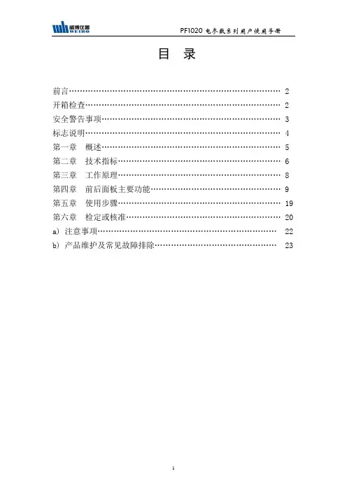
目录前言 (2)开箱检查 (2)安全警告事项 (3)标志说明 (4)第一章概述 (5)第二章技术指标 (6)第三章工作原理 (8)第四章前后面板主要功能 (9)第五章使用步骤 (19)第六章检定或核准 (20)a) 注意事项 (22)b) 产品维护及常见故障排除 (23)前言1、感谢客户购置和使用杭州威博科技有限公司的产品,为保证安全、正确地使用本公司产品,敬请用户在操作之前详细阅读本产品说明书的全部内容。
2、本说明书适用于PF1020系列电参数测量仪。
3、本说明书含有开箱检查、安全警告事项、产品的主要技术指标、工作原理、产品使用操作方法和常见故障处理等一系列内容。
在编写过程中,我们已经尽力确保本说明书内容的全面性和准确性。
如果用户在使用过程中有疑问,或者发现有不足和错误之处,欢迎直接与本所或本所授权的代理商进行联系。
用户对说明书如果有不同理解,以本所技术部的解释为准。
4、本说明书的内容或个别地方可能发生改变,恕不另行通知。
5、请用户妥善保管本说明书,以保证仪器的正常使用。
6、没有本所书面许可,不得抄袭或改编本说明书的内容,否则被视为侵权。
开箱检查用户在打开产品的包装后,请取出装箱清单,并对照本说明书逐项检查清单所列内容与实物是否完全一致,并核对主机型号与你们的订购单是否相同,如果发现有不一致的地方,请与本公司或本公司授权的代理商联系。
所有的附件和文件,请妥善保管,以便日后的操作和维护之用。
本成套设备的配件和资料包括:1.PF1020(PF1022) 电参数测量仪1台2.使用说明书1本3.产品合格证1份4.电源线1根5.产品维修卡1份6.质量跟踪卡1张7.保险丝(0.5A)2只安全警告事项在使用本系列仪器的过程中必须注意下列安全规定,如不遵守本规定,产品功能可能受损并危及人身安全。
注意:1.勿在腐蚀性环境中使用本产品(不要在含有腐蚀性液体或气体的地方使用本产品,否则将对本产品造成损害)2.勿在爆炸性环境下操作(不在存放有易爆品的地方使用本产品,否则可能危及安全。
RG-RAP1200(FE)无线设备文档版本 V1.0 归档日期 2021-12-15版权声明copyright © 2021 锐捷网络保留对本文档及本声明的一切权利。
未得到锐捷网络的书面许可,任何单位和个人不得以任何方式或形式对本文档的部分或全部内容进行复制、摘录、备份、修改、传播、翻译成其他语言、将其部分或全部用于商业用途。
、、和其他锐捷网络商标均为锐捷网络的商标。
本文档提及的其他所有商标或注册商标,由各自的所有人拥有。
免责声明您所购买的产品、服务或特性等应受商业合同和条款的约束,本文档中描述的部分或全部产品、服务或特性可能不在您的购买或使用范围之内。
除非合同另有约定,锐捷网络对本文档内容不做任何明示或默示的声明或保证。
由于产品版本升级或其他原因,本文档内容会不定期进行更新。
锐捷网络保留在没有任何通知或者提示的情况下对文档内容进行修改的权利。
本手册仅作为使用指导。
锐捷网络在编写本手册时已尽力保证其内容准确可靠,但并不确保手册内容完全没有错误或遗漏,本手册中的所有信息也不构成任何明示或暗示的担保。
前言读者对象本书适合下列人员阅读●网络工程师●技术推广人员●网络管理员技术支持●锐捷睿易官方网站:https:///●锐捷睿易在线客服:https:///?p=smb●锐捷网络官方网站服务与支持版块:https:///service.aspx●7天无休技术服务热线:4001-000-078●锐捷睿易技术论坛:/●常见问题搜索:https:///service/know.aspx●锐捷睿易技术支持与反馈信箱:*********************.cn●锐捷网络服务公众号:【锐捷服务】扫码关注本书约定1. 图形界面格式约定界面图标解释举例《》按钮点击《保存配置》按钮> 分级页面,子菜单项依次点击“无线管理 > 无线设置”“”配置项,提示信息,链接按钮等提示“保存配置成功” 点击“开启”选项点击“忘记密码”链接2. 各类标志本书还采用各种醒目标志来表示在操作过程中应该特别注意的地方,这些标志的意义如下:警告表示用户必须严格遵守的规则。
迈普路由器产品系列...................................................1 MP8800系列万兆核心路由器..........................................2 MP7500全冗余ATCA核心路由器.....................................3 MP3800系列开放式全业务汇聚路由器.................................4 MP2900系列开放式高速接入路由器....................................5 MP2824系列开放式全业务接入路由器.................................6 MP2800系列增强型宽窄带一体化智能路由器...........................7 MP1800系列3G专业级路由器 .......................................8 MP1800-20 3G无线路由器...........................................9 MP IMR800 3G无线路由器..........................................._ 迈普交换机产品系列 ..................................................1 MyPower S11800系列数据中心级核心交换机...........................2 MyPower S8900系列高性能电信级交换机...............................3 MyPower S6800系列万兆核心路由交换机...............................4 MyPower S6600系列万兆汇聚路由交换机...............................5 MyPower S5800系列数据中心级接入交换机............................6 MyPower S4320系列增强型千兆汇聚路由交换机........................7 MyPower S4300系列增强型千兆汇聚路由交换机........................8 MyPower S4220系列全千兆汇聚路由交换机.............................9 MyPower S4200系列千兆汇聚路由交换机...............................10 MyPower S4100系列电信级智能三层交换机........................11 MyPower S4000系列千兆汇聚路由交换机..........................12 MyPower S3320系列千兆智能型网管交换机........................13 MyPower S3300系列千兆智能网管型交换机........................14 MyPower S3220系列千兆智能网管型交换机........................15 MyPower S3200系列千兆智能网管型交换机........................16 MyPower S3120系列百兆智能网管型交换机........................17 MyPower S3100系列千兆智能网管型交换机.........................18 MyPower S2000系列网管型交换机.................................三、迈普安全产品系列.....................................................1 MPSec MSG4000-X1 安全网关.........................................2 MPSec MSG4000-G6 安全网关.........................................3 MPSec MSG4000-G4 安全网关........................................4 MPSec MSG4000-G2 安全网关.........................................5 MPSec MSG4000-G1 安全网关........................................6 MPSec MSG4000-F6安全网关.........................................7 MPSec VPN3000 系列VPN 网关.......................................8 电子政务外网IPSec VPN网关..........................................9 MPSec ISG1000系列网关.............................................四、迈普应用与服务产品系列..............................................1 Maipu Mico 一体化信息安防系统.......................................2 终端信息安全管理系统.................................................3 MPSec CMS证书管理服务器...........................................4 Maipu AAS迈普接入认证服务器........................................5 Maipu Portal 服务器...................................................6 迈普智能3G综合业务管理平台.........................................7 MS8000系列智能传媒服务器...........................................8 MT1000系列媒体网关.................................................9 迈普网络自动化运维系统..............................................10 Maipu Masterplan迈普统一网络管理平台............................11 Maipu DeviceMaster迈普路由交换设备管理系统.....................12 迈普管理支撑系统.................................................五、迈普无线网络产品系列.................................................1 Masterplan迈普无线有线一体化网管软件...............................2 MyPower WA2000 11n 系列智能AP ................................................................3 MyPower WA2000同频系列无线智能AP ..........................................................4 MyPower WNC6000智能无线控制器....................................5 MyPower WNC6000同频智能无线控制器................................6 MyPower WA1000 11n 系列WLAN CPE 终端 ...........................六、迈普统一通信产品系列 ...............................................1 MyPower VG 6000系列媒体网关......................................2 MyPower VG 2000系列媒体网关......................................3 MyPower VG2000-X系列媒体网关......................................4 MyPower VG 800系列媒体网关 .......................................5 MyPower VG A600系列媒体网关.......................................6 MyPower VEP600系列IP可视电话.....................................7 MyPower VEP310 系列IP 话机........................................8 MyPower VEP300 系列IP 话机........................................9 MyPower UCA个人通信助手...........................................10 MyPower VC8100 IP 通信服务器....................................11 MyPower IP电话会议系统.........................................12 MyPower VC8200协同视频服务器.................................13 MyPower MCC 融信呼.............................................14 迈普MyPower ICR录音软件 .......................................迈普路由器产品系列1 MP880C系列万兆核心路由器1.1 产品概述MP8800系列路由器是迈普通信技术股份有限公司自主研发的,全球第一款采用众核技术的路由器,是基于对行业用户业务应用的充分调研和深刻理解而推出的一款跨时代的万兆级高端骨干核心路由器。
Eaton PDG54P1200E3MNEaton Power Defense molded case circuit breaker, Globally Rated, Frame 5, Four Pole (100% N), 1200A, 100kA/480V, PXR20 LSIG w/ Modbus RTU and Relays, No TerminalsProduct specificationsModbus / relays 100 kAIC at 480 Vac56001200 A 1200 AFour-pole (100% N)600 VPD5 Global200 kAIC @240V (UL)100 kAIC Icu/ 50 kAIC Ics/ 220 kAIC Icm @380-415V (IEC) 65 kAIC @600/347V (UL)85 kAIC Icu/ 40 kAIC Ics/ 187 kAIC Icm @480V Brazil (IEC)200 kAIC Icu/ 150 kAIC Ics/ 440 kAIC Icm @240V (IEC)35 kAIC Icu/ 18 kAIC Ics/ 73.5 kAIC Icm @690V (IEC)40 kAIC Icu/ 25 kAIC Ics/ 84 kAIC Icm @525V South Africa (IEC)100 kAIC Icu/ 50 kAIC Ics/ 220 kAIC Icm @440V (IEC)100 kAIC @480/277V (UL)ElectronicClass ASpecial features Interrupt rating Frame Rated operation voltage (Ue) at AC - max Trip rating Amperage Rating Number of poles Voltage rating - max Circuit breaker type Interrupt rating range Switch off technique Class3D CAD drawing packageEaton Power Defense MCCB PDG54P1200E3MN 3D drawing Application notesPower Xpert Protection Manager x64Consulting application guide - molded case circuit breakersPower Xpert Protection Manager x32BrochuresStrandAble terminals product aidPower Defense technical selling bookletPower Defense brochurePower Defense molded case circuit breaker selection posterCatalogsPower Defense molded case circuit breakers - Frame 5 product aid Power Xpert Release trip units for Power Defense molded case circuit breakersMolded case circuit breakers catalogCertification reportsPDG5 CCC certificationEU Declaration of Conformity - Power Defense molded case circuit breakersPDG5 CSA CertificationPDG6 CCC certificatePDG5 CB reportPDG6 CSA certificationPDG5 UL authorizationInstallation instructionsPower Defense Frame 5 aux, alarm, shunt trip and uvr instructions(IL012201EN).pdfPower Defense Frame 5 breaker status module installation instructions – IL012307ENPower Defense Frame 5 walking beam installation instructions -IL012290ENPower Defense Frame 5 key interlock installation instructions -IL012294ENPower Defense Frame 4_5_6 high performance flex shaft handle mech assembly instructions - IL012296ENPower Defense Frame 5 interphase barrier kit 4 pole installation instructions - IL012293ENPower Defense Frame 2/3/4/5/6 voltage neutral sensor module wiring instructions – IL012316ENPower Defense Frame 4_5 flex shaft handle mech assembly instructions - IL012284ENPower Defense Frame 5 vertical padlockable handle lock hasp installation instructions - IL012283ENInstallation videosPower Defense Frame 5 Trip Unit Upgrade Relays Board, Animated Instructions.rhPower Defense Frame 5 UVR Trip How-To VideoPower Defense Frame 5 Shunt Trip, Aux and Alarm Trip How-To Video Power Defense Frame 5 Aux, Alarm, ST and UVR Animated Instructions.rh1Power Defense Frame 5 Trip Unit Replacement Animated Instructions Power Defense Frame 5 Trip Unit Upgrade Wire Harnesses, Animated Instructions.rhMultimediaPower Defense BreakersPower Defense Frame 6 Trip Unit How-To VideoPower Defense Frame 3 Variable Depth Rotary Handle Mechanism Installation How-To VideoPower Defense Frame 2 Variable Depth Rotary Handle Mechanism Installation How-To VideoPower Defense molded case circuit breakersPower Defense Frame 5 Trip Unit How-To VideoEaton Power Defense for superior arc flash safetySpecifications and datasheetsEaton Specification Sheet - PDG54P1200E3MNTime/current curvesPower Defense time current curve Frame 5 - PD5White papersIntelligent circuit protection yields space savingsMaking a better machineMolded case and low-voltage power circuit breaker healthSingle and double break MCCB performance revisitedIntelligent power starts with accurate, actionable dataImplementation of arc flash mitigating solutions at industrial manufacturing facilitiesMolded case and low-voltage breaker healthSafer by design: arc energy reduction techniquesEaton Corporation plc Eaton House30 Pembroke Road Dublin 4, Ireland © 2023 Eaton. All Rights Reserved. Eaton is a registered trademark.All other trademarks areproperty of their respectiveowners./socialmedia。
三相多功能电力仪表使用手册(适用于72 、80、96、120尺寸的单相电流表、单相电压表、三相电流表、三相电压表、多功能表)(液晶显示型)VER2.2 2022.11.25更新一、功能介绍● 测量功能电压测量:可直接测量或通过PT 测量三相相电压或线电压值,显示量程为999999V (测量范围10-450v )。
电流测量:可直接测量或通过CT 测量三相电流值,显示量程为9999A (测量范围0.005A-6A )。
有功功率:可测量三相总有功功率和分相(不含三相三)的有功功率,有符号位。
无功功率:可测量三相总无功功率和分相(不含三相三)的无功功率,有符号位。
功率因数:可测量三相总的功率因数和分相的功率因数,(范围为-1到+1)。
频率:可测量电网系统频率,单位为Hz 。
● 计量功能有功电量:可计量总有功电量和分相的有功电量。
电量采用累计的方式计算,除非用户清零,否则一 直累计到最大值后重新开始,电能计量的最大值为9999999kWh 。
总有功电量是分相有功电量的绝对值之和。
当电流大于0.005A 开始计量,电流大于0.25A (额定电流5A 的5%),满足计量精度标准 无功电度:可计量总的无功电量和分相的无功电量。
无功电量的单位为kvah 。
● 脉冲输出功能(选配)可选配脉冲输出:提供有功校验脉冲,为光耦开漏输出,使用时需要加5-24v 上拉,常数为3200imp/kWh 。
● 通讯功能(选配)485通讯,采用标准MODBUS-RTU 通讯协议。
波特率和数据格式可根据实际需要灵活配置。
在组网时,如果出现通讯不顺畅的现象,可在网路末端并联一个120欧姆左右的电阻进行信号匹配。
● 显示功能:采用高清白色段式液晶屏(LCD )显示,清晰直观。
● 开关量输入输出功能:(选配)仪表可选配最多8路开关量输入或4路开关量输出。
(使用方法见附加说明)二、安装尺寸和接线外形代号 外框尺寸mm A×B壳体尺寸mmC*C开孔尺寸mm E×F长度mm L72 72×72 66×66 67×67 38(短款)或58 80 83×83 75×75 76×76 38(短款)或5896 96×96 90×90 91×91 52 120 120×120110×110111×11171© Copyright reserved 安装、使用产品前请先阅读本操作手册,并保留备用1. 安装方式面板式安装,柜体的开孔尺寸可按照上表所示。