华为微波培训
- 格式:ppt
- 大小:6.67 MB
- 文档页数:165
![2024版cst微波工作室培训教程初级pdf[1]](https://uimg.taocdn.com/e386799a77eeaeaad1f34693daef5ef7ba0d1295.webp)

OTN培训小结培训时间: 07.18~7.22培训地点:华为昆明培训中心培训内容:主要分为两部分。
第一部分波分原理及OTN硬件设备介绍,第二部分上机实践OTN业务配置。
下面详细介绍下此次培训涉及的主要内容:OTN是以波分复用技术为基础、在光层组织网络的传送网,课程主要从WDM 原理,OptiX OSN 3800/6800/8800 系统硬件、设备组网与应用、电层调度方案等方面进行了讲解。
现在OTN设备的应用逐渐增加,包括承载在OTN上的大颗粒业务如GE电路的开通,OTN 设备的下沉等,加强学习OTN的知识学习是非常有必要的,授课中对波分复用技术的基本概念做详细的讲解,消除了我对一些基本概念理解上的疑惑,让我对OTN有了一定程度上的理解。
下面简要阐述一下这次培训所了解到的知识。
(1)WDM 原理随着带宽需求的日益增长,以及运营商对可运营网络的要求,运营商和设备制造商一直在不断地考虑改进业务传送技术的问题。
光传送网络的快速发展,数据业务爆炸式增长,传统的SDH、TDM带宽已经无法应对。
SDM空分复用是靠增加光纤数量的方式线性增加传输的容量,传输设备也要线性增加,TDM时分复用从传统的一次群岛四次群的复用,现在是SDH的STM-1到STIM-64的复用。
WDM 波分复用是把不同波长的光信号复用到一根光纤中进行传送,不用波长的光信号所承载的数据信号可以是相同的速率、数据格式也可以是不同的速率,不同的数据格式,可以增加新的波长特性,按用户的要求确定网络容量。
DWDM技术是利用单模光纤的带宽以及低损耗的特性,采用多个波长作为载波,允许各载波信道在光纤内同时传输。
与通用的单信道系统相比,密集WDM(DWDM)不仅极大地提高了网络系统的通信容量,充分利用了光纤的带宽,而且它具有扩容简单和性能可靠等诸多优点,特别是它可以直接接入多种业务更使得它的应用前景十分光明。
传输模式有单纤单向、单纤双向。
WDM系统的总体结构主要由发送和接收光复用终端(OMT)单元与中继线路发达(ILA)单元三部分组成,如果按组成模块来分有:光波长转换单元(OTU);波分复用器:分波/合波器(ODU/OMU );光放大器(BA/LA/PA );光监控信道/通路(OSC ); WDM 的传输媒介特性上光纤有多模和单模两种、吸收、散射、弯曲三种损耗和色散。

料contents •华为技术概述•华为网络设备培训•华为服务器与存储培训•华为操作系统与软件开发培训•华为5G技术培训•华为物联网技术培训目录华为技术概述01CATALOGUE华为成立初期,主要专注于通信设备的研发和生产,通过技术创新和产品质量赢得了市场认可。
早期阶段随着业务的发展,华为开始涉足更多领域,包括移动通信、固定通信、光网络等,逐渐形成了全方位的技术布局。
拓展阶段华为积极推进全球化战略,加强与国际通信行业的合作和交流,不断提升自身技术水平和国际竞争力。
全球化阶段华为技术发展历程研发投入创新能力产品质量知识产权华为技术核心优势华为高度重视技术研发,每年投入大量资金用于研发创新,保持技术领先地位。
华为注重产品质量和可靠性,通过严格的质量控制和测试流程,确保产品的稳定性和长期运行能力。
华为拥有强大的研发团队和创新能力,能够快速响应市场需求,推出具有竞争力的新产品和解决方案。
华为拥有众多自主知识产权和核心技术,为公司的长期发展提供了有力保障。
华为在全球通信设备市场占有重要地位,市场份额持续扩大,成为全球领先的通信设备供应商之一。
市场份额华为与全球众多运营商、企业和政府机构建立了广泛的合作关系,共同推动通信技术的发展和应用。
国际合作华为的品牌影响力不断提升,成为全球知名的科技企业之一,赢得了广泛的赞誉和认可。
品牌影响力华为积极参与国际通信技术标准的制定和推广工作,为全球通信行业的规范化和标准化做出了重要贡献。
技术标准制定华为技术在全球市场地位华为网络设备培训02CATALOGUE介绍交换机的基本工作原理,包括二层交换机和三层交换机的区别与应用场景。
交换机工作原理与类型路由器工作原理与配置VLAN 划分与配置交换机与路由器组合应用详细阐述路由器的工作原理,包括路由表、路由协议等,并介绍基本配置方法。
讲解VLAN (虚拟局域网)的划分目的、方法及配置步骤,提高网络隔离性和安全性。
通过实例介绍交换机与路由器的组合应用,实现复杂网络环境的搭建与管理。
天线调测指导书(仅供内部使用)拟制:邢子彬日期:2009-03-30 审核:日期:yyyy/mm/dd 审核:日期:yyyy/mm/dd 批准:日期:yyyy/mm/dd华为技术有限公司版权所有侵权必究修订记录天线调测指导书关键词:天线、主瓣、旁瓣、接收电平摘要:介绍了天线主瓣与旁瓣相关知识,以及单极化天线和双极化天线的调整方法。
缩略语清单:一、主瓣和旁瓣在对调天线前,需掌握天线主瓣和旁瓣的相关知识。
1、主瓣和旁瓣的定义天线辐射的电场强度在空间各点的分布是不一样的,我们可以用天线方位图来表示。
通常取其水平和垂直两个切面,故有水平方向图和垂直方向图,如图1所示为垂直方向图。
方向图中有许多波瓣,最大辐射方向的波瓣叫主瓣,其它波瓣叫旁瓣,旁瓣中可以影响对调天线的是第一旁瓣。
图1 主瓣和旁瓣2、定位主瓣微波天线的主瓣宽度很窄,通常在0.6~3.7度之间,例如:一个1.2m的天线(工作频率为23 GHz),信号电平从主瓣信号峰值衰减到零只有0.9度的方位角。
所以在定位主瓣的时候,一旦检测到信号,则只需要对天线做微调即可。
在对调天线扫描过主瓣的时候,信号电平要经历一个快速变化的过程,通过比较接收到的信号峰值可以确定天线主瓣是否对准,通常情况下主瓣信号峰值比第一旁瓣的信号峰值高20~25dB。
当两端天线同时收到对端的主瓣信号,如果两个信号强度差在2dB以内,属于允许范围。
如图2是天线在自由空间传播模型的正面图,旁瓣围绕在以主瓣为圆心的周围成放射状传播。
图2 天线水平方向图3、扫描路径在不同的俯仰角(方位角)上扫描信号时,扫描到的旁瓣信号有时被误认为主瓣信号。
如图3是天线水平方向上的辐射模型,天线在三种不同仰角位置扫描到的信号电平值:图3 三种扫描路径∙AA'表示天线的主瓣几乎对准,主瓣信号峰值在位置2,第一旁瓣信号峰值在位置1和位置3。
此时仅需在位置2微调天线的俯仰角和方位角,直至信号峰值最大。
∙BB'表示天线的俯仰角略偏离主瓣,信号峰值出现在位置4和位置5,由于天线特性原因导致位置4比位置5的信号峰值高,此时易误认为位置4是主瓣信号的峰值位置。
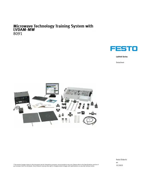
LabVolt Series DatasheetMicrowave Technology Training System with LVDAM-MW8091* The product images shown in this document are for illustration purposes; actual products may vary. Please refer to the Specifications section of each product/item for all details. Festo Didactic reserves the right to change product images and specifications at any time without notice.Festo Didactic en12/2023Microwave Technology Training System with LVDAM-MW, LabVolt SeriesTable of ContentsGeneral Description_________________________________________________________________________________3 Features & Benefits_________________________________________________________________________________4 List of Available Training Systems_____________________________________________________________________4 Additional Equipment Required to Perform the Exercises (Purchased separately) _____________________________4 Available Training Systems__________________________________________________________________________4 Equipment Description______________________________________________________________________________5 Optional Equipment Description______________________________________________________________________6Microwave Technology Training System with LVDAM-MW, LabVolt SeriesWireless transmission of a microwave signal [typical distance between the antennas: 40 cm (16 in)].General DescriptionThe Computer-Assisted Microwave Technology Training System is a complete, state-of-the-art microwave training program that includes data acquisition and instrumentation.Specifically designed for hands-on training, this integrated package of software, hardware, and courseware contains all power supplies, high-quality microwave components, and accessories required to perform the experiments.The experiments are performed using the Data Acquisition and Management for Microwave Systems software (LVDAM-MW ®). This modern software is built around a Data Acquisition Interface (DAI) that performs 12-bit A/D acquisition on four channels. The software uses the acquired data received from the interface to calculate and display the values of power and SWR measurements on a computer screen. This approach eliminates the need for a separate power meter and standing-wave ratio (SWR) meter, thereby providing high flexibility at a reduced cost.The software allows the display of a dual-trace oscilloscope, as well as the automatic computation of the line parameters on a Smith Chart. The Smith Chart is used to teach how to perform impedance matching bymeasuring the impedance of an unmatched load, and then finding the impedance and the location where the matching device must be placed to match the load.The software also displays a data table that allows the automatic recording of the displayed power andstanding-wave ratio at the click of one button. The recorded data can be saved and all the measured parameters can be plotted on the screen in the XY plane by using the included graph function. Furthermore, the software provides control and modulation of the PIN Diode and optional Voltage-Controlled RF Oscillator.The courseware is based on the Student Manual Microwave Fundamentals, which covers the basic principles of microwave signals (X-band), propagation, components, and measurements. The courseware further expands on microwave technologies with the studying of microwave tees, PIN diodes, and applications. Students can then implement and test a wireless video transmission system, using the provided PIN diode as a microwave AM modulator and additional video Equipment.1 Refer to the Computer Requirements in the System Specifications section of this datasheet if the computer is to be provided by the end-user.Microwave Technology Training System with LVDAM-MW, LabVolt Series•••••••••••Features & BenefitsProvides hands-on, system-level training in microwave technologies in the classroom Uses rugged, high-quality components designed for educational purposes Each component is identified with standard micro-wave symbolMicrowave devices and components fabricated from electroless-plated brass to standard X-band waveguide dimensionsWaveguide flanges joined by patented, precision quick fasteners, allowing rapid assembly and disassembly of system configurationsUSB Data Acquisition Interface (DAI) providing the following virtual instrumentation for the LVDAM ®-MW software: Power Meter, SWR Meter, Oscilloscope, Ammeter, and Voltmeter The DAI is "stackable" and powered by the Gunn Oscillator Power Supply, Model 9501Comprehensive manuals with theory, step-by-step laboratory exercises, and review questions Meets a variety of needs and budgets because of subsystems and options Highly safe: low-power operation levels Estimated Program Duration: 55 hoursList of Available Training SystemsQty Description Model number1Variable RF Oscillator and Resonant-Cavity Frequency Meter (add-on to microwaves with LVDAM) _______ 582073 (8091-10)Additional Equipment Required to Perform the Exercises (Purchased separately)Qty Description Model number1Personal Computer _____________________________________________________________ 579785 (8990-00)1Available Training SystemsVariable RF Oscillator and Resonant-Cavity Frequency Meter (add-on to microwaves with LVDAM)582073 (8091-10)The Variable RF Oscillator and Resonant-Cavity Frequency Meter package is an add-on to the Computer-Assisted MicrowaveTechnology Training System that contains a variable RF oscillator and a resonant-cavity frequency meter.This add-on allows the study of variable-frequency microwave measurements and applications. It also includes the StudentManual Microwave Variable-Frequency Measurements and Applications through which students learn how to convey information over a microwave link using frequency modulation and demodulation.List of EquipmentQty Description Model number1Microwave Variable-Frequency Measurements and Applications (Student Manual) _________ 580507 (85896-00)1Microwave Variable-Frequency Measurements and Applications (Instructor Guide) _________ 580508 (85896-10)1Voltage-Controlled RF Oscillator __________________________________________________ 8098726 (9511-10)Microwave Technology Training System with LVDAM-MW, LabVolt Series•••Qty Description Model number1Resonant-Cavity Frequency Meter __________________________________________________ 581840 (9524-00)1Storage for Frequency Measurement Devices _________________________________________ 581921 (9599-B0)List of ManualsDescriptionManual numberMicrowave Variable-Frequency Measurements and Applications (Workbook) __________________580507 (85896-00)Microwave Variable-Frequency Measurements and Applications (Workbook (Instructor)) ________580508 (85896-10)Table of Contents of the Manual(s)Microwave Variable-Frequency Measurements and Applications (Workbook) (580507 (85896-00))1 Microwave Frequency Measurements2 Microwave Variable-Frequency Oscillators3 Microwave Frequency Modulation and DemodulationEquipment DescriptionVoltage-Controlled RF Oscillator 8098726 (9511-10)The Voltage-Controlled RF Oscillator is a module used in certain exercises of the Microwave Training System. A built-in prescaler facilitates frequency measurement of the microwave signal produced by the RF oscillator's voltage-controlled oscillator (VCO).SpecificationsParameterValueFrequency Range 9.6-10.6 GHz (typical)Control Voltage 0-10 V dcOutput PowerAt least 8 dBm (6.3 mW)Prescaler (BNC) Output FrequencyVCO output signal’s frequency divided by 64Open-Circuit P-P Voltage 500 mV Impedance 50 ΩModulationVia a DB-9 connector used to apply a 1 kHz on/off modulation signal, or a frequency modulating signal.Microwave Technology Training System with LVDAM-MW, LabVolt SeriesResonant-Cavity Frequency Meter581840 (9524-00)The Resonant-Cavity Frequency Meter is a device used in theMicrowave Training System to perform frequencymeasurements.SpecificationsParameter ValuePower Absorption Dip0.25 dB (typical)Storage for Frequency Measurement Devices581921 (9599-B0)The Storage for Frequency Measurement Devices consists of along storage box for storing the different frequencymeasurement devices included in the Microwave TechnologyTraining System.Optional Equipment DescriptionPersonal Computer (Optional)579785 (8990-00)The Personal Computer consists of a desktop computer runningunder Windows® 10. A monitor, keyboard, and mouse areincluded.Microwave Technology Training System with LVDAM-MW, LabVolt SeriesReflecting the commitment of Festo Didactic to high quality standards in product, design, development, production, installation, and service, our manufacturing and distribution facility has received the ISO 9001 certification.Festo Didactic reserves the right to make product improvements at any time and without notice and is not responsible for typographical errors. Festo Didactic recognizes all product names used herein as trademarks or registered trademarks of their respective holders. © Festo Didactic Inc. 2023. All rights reserved.Festo Didactic SERechbergstrasse 373770 DenkendorfGermanyP. +49(0)711/3467-0F. +49(0)711/347-54-88500Festo Didactic Inc.607 Industrial Way WestEatontown, NJ 07724United StatesP. +1-732-938-2000F. +1-732-774-8573Festo Didactic Ltée/Ltd675 rue du CarboneQuébec QC G2N 2K7CanadaP. +1-418-849-1000F. +1-418-849-1666。
