NSK双列球面滚子轴承HPS
- 格式:doc
- 大小:42.00 KB
- 文档页数:13

沈阳艾姆肯轴承进出口贸易有限公司剖析各进口品牌轴承安装和保养方法NSK、NTN、IKO、KOYO、FAG、INA、TIMKEN进口轴承日本NSK进口轴承的润滑保养日本NSK轴承,材质精纯、产品精度高,品种达数十万种之多,广泛应用于不同的环境和机械,素有“机械产业的粮食”之美称,已有80余年轴承生产经验的NSK仍不断改良现有产品、研制和开发新的产品,在技术上始终保持领先优势。
nsk轴承广泛应用于各行各业中,其高速、高精度的主轴轴承,在机床行业中享有极高的声誉。
各种优良特性普遍反映在nsk 的所有轴承上,并具有较高的极限转速和承载力和性价比。
润滑对进口轴承的寿命有重要的影响作用,因而我们要适用正确的润滑保养方法。
1、油浴润滑油浴润滑是最NSK轴承中普通的润滑方法,适于低、中速轴承的润滑。
将NSK轴承一部分浸在由槽中,润滑油由旋转的轴承零件带起,然后又流回油槽油面应稍低于最低滚动体的中心。
2、滴油润滑滴油润滑适于需要定量供应润滑油得NSK轴承部件,滴油量一般每3-8秒一滴为宜,过多的油量将引起轴承温度增高。
3、循环油润滑用油泵将过滤的油输送到NSK轴承部件中,通过轴承后的润滑油再过滤冷却后使用。
由于循环油可带走一定的热量,使轴承降温,故此法适用于转速较高的轴承部件。
4、喷雾润滑用干燥的压缩空气经喷雾器与润滑油混合形成油雾,喷射NSK轴承中,气流可有效地使轴承降温并能防止杂质侵入。
此法适于高速、高温轴承部件的润滑。
5、喷射润滑用油泵将高压油经喷嘴射到NSK轴承中,射入轴承中的油经轴承另一端流入油槽。
在轴承高速旋转时,滚动体和保持架也以相当高的旋转速度使周围空气形成气流,用一般润滑方法很难将润滑油送到轴承中,这时必须用高压喷射的方法将润滑油喷至轴承中,喷嘴的位置应放在内圈和保持架中心之间。
3INA进口轴承的安装方法详解1、圆柱孔德国ina进口轴承的安装(1)用压力机压入的方法小型德国ina进口轴承广泛使用压力机压入的方法。

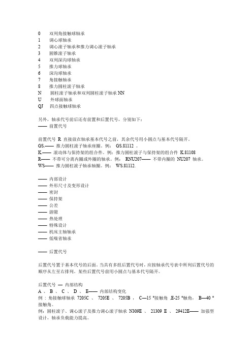
0 双列角接触球轴承1 调心球轴承2 调心滚子轴承和推力调心滚子轴承3 圆锥滚子轴承4 双列深沟球轴承5 推力球轴承6 深沟球轴承7 角接触轴承8 推力圆柱滚子轴承N 圆柱滚子轴承和双列圆柱滚子轴承NNU 外球面轴承QJ 四点接触球轴承另外,轴承代号前后还有前置和后置代号,分别如下:——前置代号前置代号R 直接放在轴承基本代号之前,其余代号用小圆点与基本代号隔开。
GS.——推力圆柱滚子轴承座圈。
例:GS.81112 。
K.——滚动体与保持架的组合件。
例:推力圆柱滚子与保持架的组合件K.81108R——不带可分离内圈或外圈的轴承。
例:RNU207——不带内圈的NU207 轴承。
WS——推力圆柱滚子轴承轴圈。
例:WS.81112.——内部设计——外形尺寸及变形设计——密封——保持架——公差——游隙——热处理——特殊设计——机床主轴轴承——低噪省轴承——后置代号后置代号置于基本代号的后面。
当具有多组后置代号时,应按轴承代号表中所列后置代号的顺序从左至右排列。
某些后置代号前用小圆点与基本代号隔开。
后置代号—内部结构A 、B 、C 、D 、E——内部结构变化例: 角接触球轴承7205C 、7205E 、7205B ,C—15 °接触角,E-25 °触角,B—40 °接触角。
例:圆柱滚子、调心滚子及推力调心滚子轴承N309E 、21309 E 、29412E——加强型设计,轴承负载能力提高。
VH——滚子自锁的满滚子圆柱滚子轴承(滚子的复圆直径不同于同型号的标准轴承)。
例:NJ2312VH 。
后置代号—轴承外形尺寸及外部结构DA——带双半内圈的可分离型双列角接触球轴承。
例:3306DA 。
DZ——圆柱型外径的滚轮轴承。
例:ST017DZ 。
K——圆锥孔轴承,锥度1 :12 。
例:2308K 。
K30- 圆锥孔轴承,锥度1 :30 。
例:24040 K30 。
2LS——双内圈两面带防尘盖的双列圆柱滚子轴承。

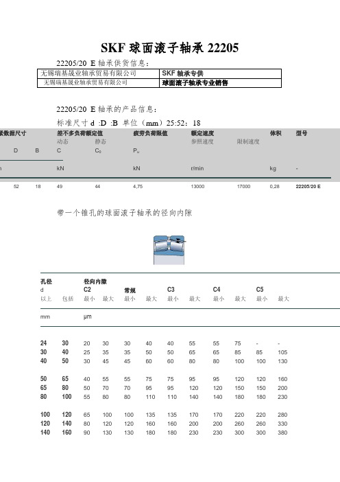
SKF球面滚子轴承2220522205/20 E轴承供货信息:无锡瑞基晟业轴承贸易有限公司SKF轴承专供无锡瑞基晟业轴承贸易有限公司球面滚子轴承专业销售22205/20 E轴承的产品信息:标准尺寸d :D :B 单位(mm)25:52:18紧数据尺寸差不多负荷额定值疲劳负荷限值额定速度体积型号动态静态参照速度限制速度D B C C0P um kN kN r/min kg -52 18 49 44 4,75 13000 17000 0,28 22205/20 E带一个锥孔的球面滚子轴承的径向内隙孔径径向内隙d C2 常规C3 C4 C5以上包括最小最大最小最大最小最大最小最大最小最大mm μm24 30 20 30 30 40 40 55 55 75 - -30 40 25 35 35 50 50 65 65 85 85 10540 50 30 45 45 60 60 80 80 100 100 13050 65 40 55 55 75 75 95 95 120 120 16065 80 50 70 70 95 95 120 120 150 150 20080 100 55 80 80 110 110 140 140 180 180 230100 120 65 100 100 135 135 170 170 220 220 280120 140 80 120 120 160 160 200 200 260 260 330140 160 90 130 130 180 180 230 230 300 300 380160 180 100 140 140 200 200 260 260 340 340 430 180 200 110 160 160 220 220 290 290 370 370 470 200 225 120 180 180 250 250 320 320 410 410 520225 250 140 200 200 270 270 350 350 450 450 570 250 280 150 220 220 300 300 390 390 490 490 620 280 315 170 240 240 330 330 430 430 540 540 680315 355 190 270 270 360 360 470 470 590 590 740 355 400 210 300 300 400 400 520 520 650 650 820 400 450 230 330 330 440 440 570 570 720 720 910450 500 260 370 370 490 490 630 630 790 790 1 000 500 560 290 410 410 540 540 680 680 870 870 1 100 560 630 320 460 460 600 600 760 760 980 980 1 230630 710 350 510 510 670 670 850 850 1 090 1 090 1 360 710 800 390 570 570 750 750 960 960 1 220 1 220 1 500 800 900 440 640 640 840 840 1 070 1 070 1 370 1 370 1 690900 1 000 490 710 710 930 930 1190 1 190 1 520 1 520 1 860 1 000 1 120 530 770 770 1 030 1 030 1 300 1 300 1 670 1 670 2 050 1 120 1 250 570 830 830 1 120 1 120 1 420 1 420 1 830 1 830 2 2501 250 1 400 620 910 910 1 230 1 230 1 560 1 5602 000 2 000 2 450 1 400 1 600 680 1 000 1 000 1 350 1 350 1 720 1 720 2 200 2 200 2 700 1 600 1 800 750 1 110 1 110 1 500 1 500 1 920 1 920 2 400 2 400 2 950带一个圆柱孔的球面滚子轴承的径向内隙孔径径向内隙d C2 常规C3 C4 C5以上包括最小最大最小最大最小最大最小最大最小最大mm μm18 24 10 20 20 35 35 45 45 60 60 75 24 30 15 25 25 40 40 55 55 75 75 95 30 40 15 30 30 45 45 60 60 80 80 10040 50 20 35 35 55 55 75 75 100 100 125 50 65 20 40 40 65 65 90 90 120 120 150 65 80 30 50 50 80 80 110 110 145 145 18580 100 35 60 60 100 100 135 135 180 180 225 100 120 40 75 75 120 120 160 160 210 210 260 120 140 50 95 95 145 145 190 190 240 240 300140 160 60 110 110 170 170 220 220 280 280 350 160 180 65 120 120 180 180 240 240 310 310 390 180 200 70 130 130 200 200 260 260 340 340 430200 225 80 140 140 220 220 290 290 380 380 470 225 250 90 150 150 240 240 320 320 420 420 520 250 280 100 170 170 260 260 350 350 460 460 570280 315 110 190 190 280 280 370 370 500 500 630 315 355 120 200 200 310 310 410 410 550 550 690 355 400 130 220 220 340 340 450 450 600 600 750400 450 140 240 240 370 370 500 500 660 660 820 450 500 140 260 260 410 410 550 550 720 720 900 500 560 150 280 280 440 440 600 600 780 780 1 000560 630 170 310 310 480 480 650 650 850 850 1 100 630 710 190 350 350 530 530 700 700 920 920 1 190 710 800 210 390 390 580 580 770 770 1 010 1 010 1 300800 900 230 430 430 650 650 860 860 1 120 1 120 1 440 900 1 000 260 480 480 710 710 930 930 1 220 1 220 1 570 1 000 1 120 290 530 530 780 780 1 020 1 020 1 330 1 330 1 7201 120 1 250 320 580 580 860 860 1 120 1 120 1 460 1 460 1 870 1 250 1 400 350 640 640 950 950 1 240 1 240 1 620 1 6202 060 1 400 1 600 400 720 720 1 060 1 060 1 380 1 380 1 800 1 800 2 3001 600 1 800 450 810 810 1 180 1 180 1 550 1 5502 000 2 000 2 550:轴和轴承座公差轴公差与合成配合公差e7, f5, f6, g5, g6公差h5, h6, h8, h9, j5公差j6, js5, js6, js7, k4公差k5, k6, m5, m6, n5公差n6, p6, p7, r6, r7, s6, s7轴承箱公差与合成配合公差F7, G6, G7, H5, H6公差H7, H8, H9, H10, J6公差J7, JS5, JS6, JS7, K5公差K6, K7, M5, M6, M76公差N6, N7, P6, P7英制轴承的配合经修改的轴直径偏差g6, h6, j5, js5, k5经修改的轴直径偏差k6, m5, m6, n6, p6经修改的轴承座孔径偏差H7, J7, J6, K6, K7经修改的轴承座孔径偏差M6, M7, N7, P7。
800mm辊式矫直机技术附件第一章:简要说明1、设备名称800mm辊式矫直机机列2、设备用途用于矫直在挤压拉伸后的部分形状不合格的型材,该矫直机包括一组主校正轮系及两组辅校正轮系,可矫型材宽度800mm,高度420mm。
3、基本性能800mm辊式矫直机,采用德国技术设计制造,有两根主校正轮轴及八套辅校正轮系组成,换辊采用单侧牌坊开合方式,十分方便,所有操作均采用液压马达或液压缸执行,方便可靠,所有元件均采用进口的德国力土乐或意大利阿托斯、MG产品。
对于大型工业型材而言,型材的校正是必不可少的,此种辊式矫直机是专为此种型材设计的大型、重载校正机。
4、主要技术要求及参数矫直型材材料:铝及铝合金型材屈服强度σs Max 350N/mm2型材宽度 Max 800mm型材高度 Max 420型材壁厚 2—12mm主校正辊工作宽度 Max850mm Min 100mm矫直辊中心距 (可调) 340—600mm矫直辊轴直径 150mm矫直轮材料尼龙,夹布胶木,硬塑料安装总功率 75kw校正速度 1—50m/min(连续可调)设备安全标准:符合我国现行的设备保护法律噪声:无负荷工作时,噪声低于85dB供电标准:电压:3*400V±10%频率:50HZ信号灯电压:220VAC控制电压:24VDCPLC控制电压:24VDC电磁阀电压:24VDC第二章:结构介绍该设备由一个用厚钢板焊接而成的坚固的底座,两个焊接结构牌坊和一个油箱泵站组成基本框架。
两列牌坊中间有两个传动轴,分别装在置于牌坊窗口中的轴承座上,由两套液压马达带动,可正反向旋转并可无级调速,上传动轴、轴承座及马达在压下机构的带动下可以上下移动,下传动轴则通过垫板调整高度。
在两列牌坊的两侧壁上装有8套辅助校正轮,它们可以旋转以适应所有不同的型材形状,辅校正轮通过丝杆可以调节开口度,通过液压马达调整压下量。
电控箱直接吊挂在(或安装在)设备上,这样整个设备可根据现场情况移动,并且方便操作,所有操作按钮均装在操作面板上。
NACHI轴承代号说明NACHI轴承代号的前缀说明:材料代号:1.B- 渗碳钢2.C- 渗碳钢3.D- 渗碳钢4.H- 高速钢5.S- 不锈钢NACHI轴承代号的后缀说明:一.接触角代号:1. C 单列角接触球轴承公称接触角100-220(标准150)2.(A)单列角接触球轴承公称接触角220-320(标准300)3. B 单列角接触球轴承公称接触角320-450(标准400)4. D 圆柱滚子轴承公称接触角240-3205. C 圆锥滚子轴承公称接触角170-240二.特殊设计:1. A 圆锥滚子轴承内圈,轴承宽度有变化2. E 滚子轴承设计改变3. J 圆锥滚子轴承套圈可互换4.S26 热稳定处理的5.S28 热稳定处理的6.W20 油孔在外圈上7.W33 油孔和油槽在外圈上8. E2 有车制保持架的调心滚子轴承9.EX 高承载能力的调心滚子轴承10.A2X 高速调心滚子轴承11.AEX 高速与高承载能力的调心滚子轴承12. V 振动机械特殊三.保持架代号:1. F 车制低碳钢保持架2. G 非金属保持架3. L 车制轻合金保持架4. MY 车制黄铜保持架5. V 无保持架6. Y 车制非铁合金保持架四.密封圈或防尘盖1.ZE Z 单面防尘盖2.ZZE ZZ 双面防尘盖3.NKE NK 单面迷宫式密封圈4.-2NKE -2NK 双面迷宫式密封圈5.NSE NSL 单面接触式密封圈6.-2NSE -2NSL 单面接触式密封圈五.套圈改变1.K 锥度:1/12圆锥孔2.K30 锥度:1/30圆锥孔3.N 外圈上有止动槽无止动环4.NR 外圈上有止动环六.双联安装1.DB 背对背安装2.DF 面对面安装3.DT 串联安装4.KB 有外隔圈的背对背安装5.+a 隔圈(a为公称宽度mm)6.U DU 等高研磨的角接触球轴承七.套筒1.+H 紧定套2.+AH 退卸套八.游隙1. C1 径向游隙C12. C2 径向游隙C23.(CN)普通径向游隙4. C3 径向游隙C35. C4 径向游隙C46. C5 径和游隙C57. C1P 径和游隙C1P8. C2P 径向游隙C2P9. C6P 径向游隙C6P10. C9na 圆柱滚子轴承(C9)11. C1na 圆柱滚子轴承(C1)12. C2na 圆柱滚子轴承(C2)13. Cna 圆柱滚子轴承(公称)14. C3na 圆柱滚子轴承(C3)15. C4na 圆柱滚子轴承(C4)16. C5na 圆柱滚子轴承(C5)17. CM 电机轴承径向游隙(深沟球轴承和不可互换的圆柱滚子轴承)18. CT 电机轴承径向游隙(可互换的圆柱滚子轴承)九.公差1.(0) JIS 0级(ISO 普通级)2. P6 JIS 6级(ISO 6级)3. P6X JIS 6X级4. P5 JIS 5级(ISO 5级)5. P4 JIS 4级(ISO 4级)6. P2 JIS 2级(ISO 2级)7. UP NACHI UP 级十.润滑脂1.ADC 壳牌Andoc C2.AV2 壳牌Alvania 2 号润滑脂3.BC325 日本标准石油公司标号3254.MTSRL Multemp SRL轴承的标记与辅助记号轴承形式●英制单列深沟球轴承:R●英制带法兰单列深沟球轴承:FR●公制单列深沟球轴承:记号省略●公制带法兰单列深沟球轴承: F●特定尺寸公制单列深沟球轴承:MR●特定尺寸公制带法兰单列深沟球轴承:MF●带沟道推力轴承:FM●无沟道推力轴承: F密封圈.防尘盖●两侧带挡圈接触式特富龙密封圈:TT●两侧钢板防尘盖:ZZ●两侧接触式橡胶密封圈:2RS润滑剂●主要的润滑脂牌号Maltemp SRL(微型、小孔径轴承的标准油脂):Alvania No.2(小型、中型轴承的标准油脂):Aero shell No.16(高温用):Molykote 33M(低负荷、低温用):Krytox 240AC(超高温用):Isoflex Super LDS18:Beacon325:标记SRL AV2 AG6 M4M K24 SL8 B32●主要的润滑剂牌号Aero shell Fluid 12(标准油脂):Windsor Lube L-245X:Antirust P2100:标记AF2 WL2 002NSK轴承补充代号说明NSK轴承的代号由基本代号、前置代号和后置代号构成。
齿轮箱的类型返回顶部返回目录齿轮箱的种类很多:1、按照传统类型可分为圆柱齿轮齿轮箱、行星齿轮箱以及它们互相组合起来的齿轮箱;2、按照传动的级数可分为单级齿轮箱和多级齿轮箱;3、按照转动的布置形式又可分为展开式齿轮箱、分流式齿轮箱和同轴式齿轮箱以及混合式齿轮箱等等。
齿轮箱特点返回顶部返回目录1、采用通用设计方案,可按客户需求变型为行业专用的齿轮箱。
2、实现平行轴、直交轴、立式、卧式通用箱体,零部件种类减少,规格型号增加。
3、采用吸音箱体结构、较大的箱体表面积和大风扇、圆柱齿轮和螺旋锥齿轮均采用先进的磨齿工艺,使整机的温升、噪声降低、运转的可靠性得到提高,传递功率增大。
4、输入方式:电机联接法兰、轴输入。
5、输出方式:带平键的实心轴、带平键的空心轴、胀紧盘联结的空心轴、花键联结的空心轴、花键联结的实心轴和法兰联结的实心轴。
6、安装方式:卧式、立式、摆动底座式、扭力臂式。
7、齿轮箱系列产品有3~26型规格,减速传动级数有1~4级,速比1.25~450;和R、K、S系列组合得到更大的速比。
齿轮箱的在风力电机组中的应用返回顶部返回目录齿轮箱在风力发电机组中的应用很广泛,在风力发电机组当中就经常用到,而且是一个重要的机械部件,其主要功用是将风轮在风力作用下所产生的动力传递给发电机并使其得到相应的转速。
通常风轮的转速很低,远达不到发电机发电所要求的转速,必须通过齿轮箱齿轮副的增速作用来实现,故也将齿轮箱称之为增速箱。
齿轮箱承受来自风轮的作用力和齿轮传动时产生的反力,必须具有足够的刚性去承受力和力矩的作用,防止变形,保证传动质量。
齿轮箱箱体的设计应按照风电机组动力传动的布局安排、加工和装配条件、便于检查和维护等要求来进行。
应注意齿轮箱轴承支承和机座支承的不同方向的反力及其相对值,选取合适的支承结构和壁厚,增设必要的加强筋。
齿轮箱筋的位置须与引起箱体变形的作用力的方向相一致。
其次齿轮箱还有如下的作用:1、加速减速,就是常说的变速齿轮箱。
NSK双列球面滚子轴承HPSSpherical Roller BearingsHPS, redefining the standard.Trademark registration pendingLifeLimiting Speed2 times the operating life(maximum)20% higher(maximum)Des ign Techn ologyExclusive through analytical NSK design advanced technologyMaterial TechnologyState-of-the-art material technology through detailed analysis of raw materialManufacturing TechnologyThe most advanced production system guarantees outstanding quality controlContinually developing products with greater strength and higher accuracy, NSK’s new HPS fully incorporate the advan tages of NSK’s world-class design, materials, and manufacturing technology, setting a new standard for bearings.12High performance in diverse applications with reduced maintenance costs and more compact designHPS spherical roller bearings meet the needs of various equipment for components with reduced maintenance costs and unsurpassed functionality. By taking full advantage of NSK’s wealth of experience and expertise, HPS spherical roller bearings realize unprecedented endurance and high limiting speeds to support downsizing while at the same time improving performance and lengthening equipment operating life. Just what you would expect from NSK, the leading bearing company.LifeLimiting Speed2 timesFeatures of HPS Spherical Roller Bearingsthe operating life (maximum)20% higher(maximum)Long LifeLower Maintenance CostMaintenance costs are an important factor in reducing total equipment costs. HPS spherical roller bearings realize twice the operating life ofconventional products, and longer operating life leads to lower maintenance costs.FlexibleApplicable to a variety of applicationsWith improved cage resistance to wear at higher speeds over longer period of operation, HPS spherical roller bearings deliver high performance to a variety of applications.CompactContributing to equipment downsizingAchieving longer operating life can be realized together with the selection of smaller bearings. HPS spherical roller bearings allow compact design for various equipment, thereby supporting the demand for downsizing.34Long operating life reduces maintenance costHPS spherical roller bearings demonstrate twice the operating life of conventional EA Series bearings for longer equipment operating life that lowers maintenance costs.ComparisonHPS EA CDLifeLimiting SpeedHigh-speed, long-term operability provides increased flexibility across a wide range of applications.HPS spherical roller bearings exhibit dramatically reduced cage wear at higher speeds over longer periods of operation. As a result, limiting speeds are increased to provide greater flexibility across an extensive range of applications.2 times the operating life(maximum)20% higher(maximum)Limiting speedLifeHPSEACD56Innovative design drawing upon a variety of technologies leads to high performance in next-generation productsTechnologyAdoption of state-of-the-art materialsHPS spherical roller bearings are made from NSK’s highcleanliness Z steel. This steel features greater fatigue strength. In addition, special surface treatment makes it more resistant to wear and more durable in a variety of applications.Bearing Technology CenterAmerican Technology CenterEuropean Technology CenterInnovative design developed through enhanced structural analysisThe HPS cage incorporates a roller guide function in place of a guide ring. Eliminating the guide ring and optimizing the design of the inner and outer ring configuration facilitates the placement of additional, larger rollers. Optimized design for the internal specifications and improved press technology greatly increase load capacity, and realize longer life. Special surface treatment further strengthens the cage, reducing wear, heat and friction; it also allows for higher limiting speeds.Cage design features stronger resistance to wearBy utilizing the space gained from eliminating the guide ring and improving the design through advanced structural analysis, cage strength has been increased dramatically. The high-precision roller guide functionin place of the guide ring, united with a special surface treatment, strengthens the cage against wear and increases the limiting speeds.Advanced production system ensures outstanding qualityAs global leaders in the bearing industry, we have continually invested in developing and refining our manufacturing technology and quality control procedures so that we are able to manufacture bearings of exceptional quality and accuracy.Cage Cage Guide ringRollers Increased size and numberOuter Ring High-temperature operability Lubrication groove and holes Cage Flange High limiting speedInner Ring High-temperature operabilityNSK old type bearingHPSBearing Interior Design Comparison Elimination of the guide ring allowed for a design change that improves cage balance and strength.Cage High-strength pressed steel Special surface treatment78HPS Spherical Roller Bearing TableB r r B r ra raDynamic Equivalent Load P=XFr+YFa Fa / Fr≤e X 1 Y Y3 X 0.67 Fa / Fr>e Y Y2 Table 1 Dimensions of Oil Grooves and Holes Unit: mmNominal Outer Ring Width CTable 2 Number of Oil HolesNominal Outer Ring Diameter (mm)over18 30 40 50 65 80 100 120 160 200 250 315 400incl.30 40 50 65 80 100 120 160 200 250 315 400 —Hole Oil Groove Diameter d0H Width W5 6 7 8 10 12 15 20 25 30 35 40 40 2.5 3 4 5 6 8 10 12 15 20 20 25 25overincl.Number of Holes4 6 6 6 6 8 8 8 8 8 8C WφDφdφDφdφDaφdad0H— 180 250 315 400 500 630 800 1 000 1 250 1 600Static Equivalent Load P0=Fr+Y0 Fa The values for e, Y2, Y3 and Y0 are given in the table below.Cylindrical BoreTapered BoreDimensions (mm) d40Basic Load Rating r (min)1.1 1.5 1.5 1.1 1.5 1.5 1.1 2 2 1.5 2 2 1.52.1 2.1 1.5 2.1 2.1 1.5 2.1 2.1 1.5 2.12.1 2 2.1 2.1 2 3 3 2 3 3 2.1 3 2.1 3 2.1 3 2.1 3 3Limiting Speeds (min-1) Grease6 700 6 000 5 300 6 000 5 000 4 500 5 600 4 500 4 300 5 300 4 500 3 800 4 800 3 800 3 600 4 300 3 600 3 200 4 000 3 200 3 000 4 000 3 200 2 800 3 600 3 000 2 600 3 400 3 000 2 400 3 200 2 800 2 400 3 000 2 200 2 800 2 000 2 600 1 900 2 400 1 700 2 200Bearing Numbers Cylindrical Bore22208EAE4 21308EAE4 22308EAE4 22209EAE4 21309EAE4 22309EAE4 22210EAE4 21310EAE4 22310EAE4 22211EAE4 21311EAE4 22311EAE4 22212EAE4 21312EAE4 22312EAE4 22213EAE4 21313EAE4 22313EAE4 22214EAE4 21314EAE4 22314EAE4 22215EAE4 21315EAE4 22315EAE4 22216EAE4 21316EAE4 22316EAE4 22217EAE4 21317EAE4 22317EAE4 22218EAE4 21318EAE4 22318EAE4 22219EAE4 22319EAE4 22220EAE4 22320EAE4 22222EAE4 22322EAE4 22224EAE4 22324EAE4 22226EAE4Abutment and Fillet dimensions (mm) (min)47 49 49 52 54 54 57 60 60 64 65 65 69 72 72 74 77 77 79 82 82 84 87 87 90 92 92 95 99 99 100 104 104 107 109 112 114 122 124 132 134 144Constant ra (max)1 1.5 1.5 1 1.5 1.5 12 2 1.5 2 2 1.5 2 2 1.5 2 2 1.5 2 2 1.5 2 2 2 2 2 2 2.5 2.52 2.5 2.5 2 2.5 2 2.5 2 2.5 2 2.5 2.5Axial Load Factor Y23.6 3.9 2.8 3.94.3 2.9 4.3 4.4 2.8 4.3 4.4 2.9 4.4 4.5 3 4.2 4.6 3 4.3 4.6 3 4.54.6 3 4.6 4.4 3 4.6 4.3 3.1 4.3 4.3 3.1 4.3 3.1 4.3 3 4 3.1 3.9 3.1 3.8Mass Y02.4 2.6 1.9 2.6 2.8 1.9 2.8 2.9 1.9 2.8 2.9 1.9 2.9 3 1.9 2.7 3 2 2.8 3 2 3 3 2 3 2.9 2 3 2.8 2 2.8 2.8 2 2.8 2 2.8 2 2.6 2 2.6 2 2.5D80 90 90 85 100 100 90 110 110 100 120 120 110 130 130 120 140 140 125 150 150 130 160 160 140 170 170 150 180 180 160 190 190 170 200 180 215 200 240 215 260 230B23 23 33 23 25 36 23 27 40 25 29 43 28 31 46 31 33 48 31 35 51 31 37 55 33 39 58 36 41 60 40 43 64 43 67 46 73 53 80 58 86 64(N) Cr113 000 118 000 170 000 118 000 149 000 207 000 124 000 178 000 246 000 149 000 178 000 292 000 178 000 238 000 340 000 221 000 264 000 375 000 225 000 310 000 425 000 238 000 310 000 485 000 264 000 355 000 540 000 310 000 360 000 600 000 360 000 415 000 665 000 415 000 735 000 455 000 860 000 605 000 1 030 000 685 000 1 190 000 820 000Cor99 500 111 000 153 000 111 000 144 000 195 000 119 000 174 000 234 000 144 000 174 000 292 000 174 000 244 000 340 000 230 000 275 000380 000 232 000 325 000 435 000 244 000 325 000 505 000 275 000 375 000 565 000 325 000 395 000 630 000 395 000 450 000 705 000 450 000 780 000 490 000 930 000 645 000 1 120 000 765 000 1 320 000 940 000Oil8 500 7 500 6 700 7 500 6 300 5 600 7 100 5 600 5 300 6 700 5 600 4 800 6 000 4 800 4 500 5 300 4 500 4 000 5 300 4 000 3 800 5 000 4 000 3 600 4 500 3 800 3 400 4 300 4 000 3 200 4 000 3 600 3 000 3 800 2 800 3 600 2 600 3 200 2 400 3 000 2 200 2 600Tapered Bore (1)22208EAKE4 21308EAKE4 22308EAKE4 22209EAKE4 21309EAKE422309EAKE4 22210EAKE4 21310EAKE4 22310EAKE4 22211EAKE421311EAKE4 22311EAKE4 22212EAKE4 21312EAKE4 22312EAKE422213EAKE4 21313EAKE4 22313EAKE4 22214EAKE4 21314EAKE422314EAKE4 22215EAKE4 21315EAKE4 22315EAKE4 22216EAKE421316EAKE4 22316EAKE4 22217EAKE4 21317EAKE4 22317EAKE422218EAKE4 21318EAKE4 22318EAKE4 22219EAKE4 22319EAKE422220EAKE4 22320EAKE4 22222EAKE4 22322EAKE4 22224EAKE422324EAKE4 22226EAKE4da(max)49 54 52 54 65 59 60 72 64 65 72 73 72 87 79 80 94 84 84 101 91 87 101 97 94 109 103 101 108 110 108 115 115 115 121 119 130 129 145 142 157 152(max)73 81 81 78 91 91 83 100 100 91 110 110 101 118 118 111 128 128 116 138 138 121 148 148 130 158 158 140 166 166 150 176 176 158 186 168 201 188 226 203 246 216Da(min)70 75 77 75 89 86 81 98 93 89 98 103 98 117 111 107 126 119 111 135 129 117 134 137 126 146 145 135 142 155 142 152 163 152 172 160 184 178 206 190 222 204e0.28 0.25 0.35 0.25 0.23 0.34 0.24 0.23 0.35 0.23 0.23 0.34 0.23 0.22 0.34 0.24 0.22 0.33 0.23 0.22 0.33 0.22 0.22 0.33 0.22 0.23 0.33 0.22 0.24 0.33 0.24 0.24 0.33 0.24 0.33 0.24 0.33 0.25 0.33 0.25 0.32 0.26Y32.4 2.7 1.9 2.7 2.9 2 2.9 3 1.9 2.9 3 2 3 3 2 2.83.1 2 2.9 3.1 2 3 3.1 2 3.1 3 23.1 2.9 2.1 2.9 2.9 2.1 2.9 2.1 2.9 2 2.7 2.1 2.7 2.1 2.6(kg) approx0.50 0.73 0.98 0.55 0.96 1.34 0.61 1.21 1.78 0.81 1.58 2.30 1.10 1.98 2.891.512.453.52 1.58 3.004.28 1.64 3.645.26 2.01 4.326.23 2.54 5.207.23 3.30 6.108.56 4.049.91 4.84 12.7 6.99 17.6 8.80 22.2 11.04550556065707580859095 100 110 120 130Note (1) The suffix K indicates that the bearing has a tapered bore (taper 1:12). Remarks 1. The maximum operating temperature of standard HPS spherical roller bear ings is 200˚C 2. The suffix E4 indicates that the bearing has an oil groove and holes. (The numbers and dimensions of oil grooves and holes are shown in Tables 1 and 2.)910。