Audio Jack training material for Sales_130227
- 格式:pdf
- 大小:2.14 MB
- 文档页数:53

STM32L552E-EV top view. Picture is not contractual.Features•STM32L552ZET6QU microcontroller featuring 512 Kbytes of Flash memory and 256 Kbytes of SRAM in LQFP144 package• 2.8" 240 x 320 pixel-262K color TFT LCD module with parallel interface and touch panel•USB Type-C™ Sink device FS•On-board current measurement•SAI Audio CODEC•ST-MEMS digital microphones•512-Mbit Octal-SPI Flash, 64-Mbit Octal HyperRAM, 16-Mbit SRAM, 128-Kbit I2C EEPROM• 4 user LEDs•User, Tamper and Reset push-buttons•4-direction joystick with a selection button• 1 touch sensing button•Light-dependent resistor (LDR)•Potentiometer•Coin-battery cell holder for power backup•Power-metering demonstration with dual-channel, sigma-delta modulator •Board connectors:–USB Type-C™–microSD™ card–Smartcard socket–Stereo headset jack including analog microphone input–Audio jack for external speakers–2xDB9 for external RS-232 port and CAN FD–JTAG and TRACE ETM debugger–Connectors for ADC input and DAC output–I/O expansion connectors–STMod+ expansion connector–PMOD expansion connector–Audio daughterboard expansion connector–Motor-control interface expansion connector–I2C expansion connector•Flexible power-supply options: ST-LINK USB V BUS or external sources•On-board ST-LINK/V2-1 debugger/programmer with USB re-enumeration capability: mass storage, Virtual COM port and debug port•Comprehensive free software libraries and examples available with the STM32CubeL5 MCU Package•Support of a wide choice of Integrated Development Environments (IDEs): Keil®MDK-ARM, IAR™ EWARM, GCC-based IDEsEvaluation board with STM32L552ZE MCUSTM32L552E-EVData briefDescriptionThe STM32L552E-EV Evaluation board is designed as a complete demonstration and development platform for STMicroelectronics Arm® Cortex®-M33 core with TrustZone® and the ARMv8-M mainline security extension.The STM32L552E-EV Evaluation board is based on an ultra-low-powerSTM32L552ZET6QU microcontroller with 512 Kbytes of Flash memory and256 Kbytes of SRAM, one external memory interface supporting an LCD interface, one Octo-SPI memory interface, one USB Type-C™ FS with Power Delivery controller, two SAI ports, four I²C buses, six USART ports, three SPI interfaces, one CAN FD controller, one SDMMC interface, 2x12-bit ADC, 2x12-bit DAC, two operational amplifiers, two ultra-low comparators, four digital filters for sigma-delta modulator, up to 16 timers, touch-sensing capability, and debugging supported by SWD, JTAG and ETM interface.The full range of hardware features on the board helps the user to evaluate all the peripherals (USB FS, USART, digital microphones, ADC and DAC, dot-matrix TFT LCD, LDR, SRAM, octal Flash memory device, microSD™ card, sigma-delta modulators, smartcard, CAN FD transceiver, I²C, EEPROM), and develop applications. Extension headers allow easy connection of a daughterboard or wrapping board for a specific application.An ST-LINK/V2-1 is integrated on the board, as embedded in-circuit debugger and programmer for the STM32 MCU and the USB Virtual COM port bridge.Ordering information 1Ordering informationTo order the STM32L552E-EV Evaluation board, refer to Table 1. For a detailed description, refer to its usermanual on the product web page. Additional information is available from the datasheet and reference manual ofthe target STM32.Table 1. List of available products1.LCD board.1.1Product markingEvaluation tools marked as “ES” or “E” are not yet qualified and therefore not ready to be used as referencedesign or in production. Any consequences deriving from such usage will not be at ST charge. In no event, ST willbe liable for any customer usage of these engineering sample tools as reference design or in production.“E” or “ES” marking examples of location:•On the targeted STM32 that is soldered on the board (for illustration of STM32 marking, refer to the STM32 datasheet “Package information” paragraph at the website).•Next to the evaluation tool ordering part number that is stuck or silk-screen printed on the board.Some boards feature a specific STM32 device version, which allows the operation of any bundled commercialstack/library available. This STM32 device shows a "U" marking option at the end of the standard part numberand is not available for sales.In order to use the same commercial stack in his application, a developer may need to purchase a part numberspecific to this stack/library. The price of those part numbers includes the stack/library royalties.1.2CodificationThe meaning of the codification is explained in Table 2. The order code is mentioned on a sticker placed on thetop side of the board.Table 2. Codification explanationDevelopment environment 2Development environmentThe STM32L552E-EV Evaluation board runs with the STM32L552ZET6QU 32-bit microcontroller based on theArm® Cortex®-M33 core with TrustZone® and the ARMv8-M mainline security extension.Note:Arm is a registered trademark of Arm Limited (or its subsidiaries) in the US and/or elsewhere.2.1System requirements•Windows® OS (7, 8 and 10), Linux® 64-bit, or macOS®•USB Type-A to Micro-B cableNote:macOS® is a trademark of Apple Inc. registered in the U.S. and other countries.2.2Development toolchains•Keil® MDK-ARM (see note)•IAR™ EWARM (see note)•GCC-based IDEs®Note: Array2.3Demonstration softwareThe demonstration software, included in the STM32Cube MCU Package corresponding to the on-boardmicrocontroller, is preloaded in the STM32 Flash memory for easy demonstration of the device peripherals instandalone mode. The latest versions of the demonstration source code and associated documentation can bedownloaded from .Revision historyTable 3. Document revision historyIMPORTANT NOTICE – PLEASE READ CAREFULLYSTMicroelectronics NV and its subsidiaries (“ST”) reserve the right to make changes, corrections, enhancements, modifications, and improvements to ST products and/or to this document at any time without notice. Purchasers should obtain the latest relevant information on ST products before placing orders. ST products are sold pursuant to ST’s terms and conditions of sale in place at the time of order acknowledgement.Purchasers are solely responsible for the choice, selection, and use of ST products and ST assumes no liability for application assistance or the design of Purchasers’ products.No license, express or implied, to any intellectual property right is granted by ST herein.Resale of ST products with provisions different from the information set forth herein shall void any warranty granted by ST for such product.ST and the ST logo are trademarks of ST. For additional information about ST trademarks, please refer to /trademarks. All other product or service names are the property of their respective owners.Information in this document supersedes and replaces information previously supplied in any prior versions of this document.© 2019 STMicroelectronics – All rights reserved。
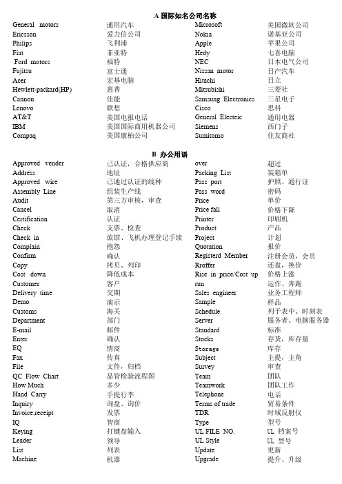
Manufacture UL 档案号UL 型号更新提升、升级印刷机产品计划报价注册会员,会员还盘,换价超过装箱单护照、通行证密码单价价格下降AcerHewlett-packard(HP)佳能CompaqCannonLenovoAT&TIBMGeneral motorsEricssonPhilipsFiatFord motorsFujitsu美国国际商用机器公司福特富士通宏基电脑惠普美国康柏公司通用汽车爱力信公司飞利浦菲亚特联想美国电报电话NEC Nissan motor Hitachi Mitsubishi Microsoft Nokia Apple Hedy 三菱社三星电子Samsung Electronics Cisco General Electeic Siemens 西门子住友商社Sumitomo 美国微软公司诺基亚公司苹果公司七喜电脑日本电气公司日产汽车日立Approved wireAssembly LineAuditCancelA 国际知名公司名称B 办公用语Approved venderAddress思科通用电器ConfirmCopyCost downCustomerCertificationCheckCheck inComplainDelivery timeDemoCustomsover Packing List Pass port Pass word Price Price fall Printer Rroffer Rise in price/Cost up run Sales engineer Product Project Quotation Registerd Member Sample Schedule 已认证,合格供应商地址已通过认证的线种组装生产线第三方审核,审查取消认证支票、检查降低成本客户交期演示旅馆、飞机办理登记手续抱怨确认拷贝、列印海关确认情商传真文件,归档品管检验流程图多少价格上涨运作、奔跑业务工程师样品列于表中、时刻表部门邮件手提行李询盘、询价Server Standard Stocks Storage Subject Survey Team Teamwork Telephone Terms of trade DepartmentE-mailEnterEQFaxFileQC Flow ChartHow MuchListMachineHand CarryInquiryInvoice,receiptIQ发票智商打键盘输入领导KeyingLeader主提,主角审查团队团队工作服务者、电脑服务器标准存货,库存量库存电话贸易条件时域反射仪型号TDR Type UL FILE NO.UL Style Vender,supplier,seller 生产Update Upgrade 列表机器抗张测试测试报告厚度镀锡试单传输延迟差异速度缠绕开关系统电话线回波损耗排程小型计算机系统接口服务遮蔽邵氏硬度进度订单紫色质量控制系统研发红色计划执行检查实施百分比粉红插头Test Test standard Thickness Tin Try order Speed Spiraling Switch System Telephone Cable Tensile strength Schedule SCSI cable Service Shield Shore A Skew Process Purchase order purple RD (research and develop)Red Return loss check Do Percent Quality control system Pink Plug 绿色合作伙伴绿色灰色高品质雇员漆包线环保母头档案扁性铜包纲串音DC 连接线延误拉伸电磁兼容性椭圆形国际标准色卡的一种编织Out diameter Oval PDCA : Plan 黑色action 为什么滑鼠线贴牌代工厂商橙色线经什么时候哪里棕色到岸价离岸价同轴线信号线导体MaxumumMeetingNotebookOffer 最大的会议机种、模型网络分析器笔记本,手提电脑发盘ModelNetwork analysisWhat 什么原料备忘录AC 连接器转换器Material When Where Who Why 谁BlackAmerican Wire Gauge (AWG)Application Wiring Material(AWM)AttenuationAudioWorkshop C 专业术语AC power cord adaptor 车间Pantone card蓝色Bule美国线规电线用料衰减音频Automobile wireBareBending test毫米显示器用线成型,塑造Memo Mini meter Monitor Cable BrownMoulding Mouse Cable OEM; original entrusted manufacture Braidingorange 汽车线裸露弯曲测试ConductorCopper clad steelCrosstalkDC cordC.I.FF.O.BCoaxial CableCommunication CableEnamelEnvironment protectFemaleFileDelayElogationEMCEmployeeKeyboard CableLabelFlatGP :Green partnerGreenGrey外被键盘线标签网络线High QualityImpedanceInsulationLan-Cable ItemJacket阻抗绝缘项目Electrical testing Limited CSA Pantone FEMALE Both side condnctor JACK UL UL DATE Product Spec Approved Description Bill of Material Product Drawing Material Test Report Conditional Approval 标准色卡母头双面导电插座UL 资料产品规格书承认条件承认允收加拿大官方标准尼龙描述材料表图片材质证明美国官方标准公差角度镀金/一般镀铜镀锡磷青铜单位比例包装全雾面半雾面缠绕地线编织CopperizeTinningBronze PhosphorNylon SpiraeDrainBraidToleranceAngleGild /G/FInsulator UnitScalePackingMatteNon-brighter绝缘阻抗接触阻抗开路短路绝缘体Hi-pot Insulation resistance Contact resistanle Open Short 螺母芯线装配壳间距电气测试高压测试双排单排马口铁橡皮筋被被镍零件开关不锈钢钢、铁纸箱压条铁粉芯锡D 公司产品英语专用术语知识Aluminum foil Ferrite core Tin 线材后/下铁壳视频重量白色线束黄色铝箔Conductor Hood Pitch Single row Mater cover Rubber band Jaket Nicked Clinch Switch Stainless Steel Carton Lacing cover Double row Weight White Parts Wiring harnesses Yellow Video 迷你带连接线屏蔽美纹纸发光二极管泡沫插头电线醋酸胶布端子塑壳简易牛角夹链袋电阻器胶料螺丝铜箔PE 袋标签连接器套管纸箱防水袋ResistorInsulation clothsBox headerZip-lock bagShield paperHi-Temp tapeFoamLED信用状无铅长度列表低重金属底毒公头前/上铁壳WireScrewCopper FoilPE BagLABLEConntectorPlugTerminalHousingMini tieHook-up wrieFront(up)shellBack(down)shellShrineCartonWaterpro of BagPlaststic Compoundmale Lead free (L F)LengthListLow metal (LM)CableLetter of creditLow toxicant (L.T)AWG BSC CEM CEO CFO CIF COO CSA DCC DEMEA DQE FAP ECN ECR EE ERP ESP ETD EMEA FOB FOM EQC GR&R HR HRM IE IPQC IPR IQC ISO 工程变更通知单工程变更需求电子工程/电子工程师企业资源规则员工提案计划首行执行官首席财务长到岸价格首席营运官加拿大标准协会资料管制中心设计失效模式效应分析设计品质审查员工协助方案Purpel Center Design 美国线规平衡积分卡托外加工制造商黑色红色白色E 英文缩写White Green Black Marking line 设计客户Customer Red 绿色Bend Check Cut Develop Damage Marking text Yellow 摇摆检验裁线开发损伤负极正极中心紫色银白色兰色黄色Orange Brown Gray Transparent Nature Silver white Blue 棕色打端子数量灰色透明色自然色Single shield Double shield Strapping Strip Crimping Amount 橙色Mark Brass Roll Bracket Twistd pair Length 线端处理打卷支架对绞线长度单隔离双隔离标志黄铜成型亮面焊接公头Solder Male Molding Lighter Chief Excutive OfficerChief Finance OfficerChost Insurance and EreightChief Operation OfficerAmerica Wire GaugeBalance Score CareContract Electronic Manufacture Employee Assistant programEengineering Change NoticeEngineering Change RequestElectronic Engineer /Electrical Engineering Canadiam Standard Association Document Control CenyerDesign Failure Mode Effect Analysis Design Quality EvaluationFree on BoardFoundation of ManagementEnished Quality ControlGuage Repeatahility &Reproduciibility Enterprise Resource PlanningEmployee Suggestion Program Estimated Time of DepartureFailure Mode and Effect Analysis In-Process RepairIncoming Quality ControlInternational Standards Qrganization Human ResoureHuman Resoure Management Industry EngineeringIn Process Quality Control预定出发时间失效模式分析离岸价格基础管理研究工业工程制程品质管制制程维修来料品质管制成品品质管制量具再现性与再生性分析人力资源人力资源管理国际标准组织化IT JIT KPI L/O LRR M2P ME MPS MRP MTBF ODM OEM ORM P&L PBT PQC PRD PSM QA QC QE SAP SCM SPC TQM TWI UL VAP VQM VQT WIP 在制品Information Technology Material to PriceManufacture/Mechanim Engineering Master Production Scheduling Material Requirement Planning Just in TimeKey Performance Indicator Lahour &OverheadLot Rejected RateProcess Quality ControlPerformance Review Development Purchase Supply Management Quality AssuranceMean Time Between Failure Original Design Manufacture Original Equipment Manufacture Operation Review Meeting Work in Process Training Within Industry Underwriter"s Laboratories Value Added Productivity Vendor Quality Management Vendor Quality TeamSystem Application Production Supply Chain Management Quality ControlQuality EngineeringProfit and lossProfit Before Tax管理费用批退率材料价格比制造/机构工程师信息技术时间管理主要营运指标原始设备制造商经营检讨损益税前利润主生产计划物料需求计划平均故障隔离时间原始设计制造商品质控制品质工程物料系统运用软件供应链管理制程品质管理绩效评估与发展采购供应商管理品质保证附加值供应商品质管理供应商品质辅导统计制程管制全面质量管制工厂基层主管训练美国保险协会实验室Statistical Process Control Total Quality Management表务器接口。

NS5S1153MUGEVBDPDT USB 2.0 High Speed /Audio Switch with Negative Swing Capability Evaluation Board User's ManualOverviewThe NS5S1153 is a DPDT switch for combined true −ground audio and USB 2.0 high speed data applications. It allows portable systems to use a single port to pass either USB data or audio signals from an external headset; headset; the two channels being compliant to USB 2.0, USB 1.1 and USB 1.0.The switch is capable of passing signals with negative voltages as low as 2 V below ground. The device featuresshunt resistors on the audio ports. These resistors are switched in when the audio channel is off and provide a safe path to ground for any charge that may build up on the audio lines. This reduces Pop & Click noise in the audio system.The NS5S1153 is also equipped with V BUS detection circuitry to immediately switch to USB mode in the event that a voltage is detected on V BUS .The NS5S1153 is housed in a space saving, ultra low profile 1.4 x 1.8 x 0.5 mm 10 pin mQFN package.Figure 1. Board PictureEVAL BOARD USER’S MANUALNS5S1153 – BOARD SCHEMATICFigure 2. Board SchematicTable 1. NS5S1153 – BOARD CONNECTIONSSymbol Description SUPPLYV CC, GND This is the positive and the return connection for power supply. SETUPJ4 − ASEL This is the line selection header.J5 − VBUS_CTRL This is VBUS comparator input.SIGNALSJ1 − INPUT This USB connector Male A type is the common data and audio lines.J2 − AUDIO This connector is a 3.5 mm Stereo Jack Connector.J3 − USB This USB connector Male B type is the high speed USB signaling path.NS5S1153 – TEST PROCEDUREEquipment needed•Power Supply•Digital Ohm Meter•Desktop or Laptop with Windows XP or higher •USB Memory Stick •USB Type A to USB Type BTable 2. BACKGROUND: ASEL AND VBUS TRUTH TABLEA SEL V BUS L, R D+, D−L, R ShuntLow Low ON OFF OFFLow High OFF ON ONHigh X ON OFF OFF Test1.Connect ASEL to ‘0’ (J4) and VBUS_CTRL to ‘1’(J5).2.Connect the power supply at3.6 V from VCC to GND. The supply current should be around 20 m A. The impedance measured from COM+ (TP3) toD+ (TP5) is over 10 M W.The impedance measured from COM− (TP4) toD− (TP6) is over 10 M W.The impedance measured from COM+ (TP3) toR(TP7) is close to 3 W.The impedance measured from COM− (TP4) to L (TP8) is close to 3 W.3.Insert a USB cable from USB terminal (J3) to the laptop or desktop.The impedance measured from L (TP8) and R (TP7) to GND is closed to 118 W.4.Place a USB Memory Stick connected to USB terminal (J1). The device is being recognized.NS5S1153 – COMPONENTS SELECTIONInput CapacitorA 0.1 m F X5R ceramic capacitor or larger must bypass V CC input to the ground. This capacitor should be placed as close as possible to this input.ESD DiodeIn order to protect the device against transient voltages, an external bi−directional ESD / IEC diode is recommended on COM+ and COM− pin. The ESD11N is designed to protect voltage sensitive components that require ultra−low capacitance from ESD and transient voltage events. Excellent clamping capability, low capacitance, low leakage, and fast response time, make these parts ideal for ESD protection on designs where board space is at a premium. Because of its low capacitance, it is suited for use in high frequency designs such as USB 2.0 high speed and antenna line applications.Table 3. NS5S1153 – BILL OF MATERIALDesignator Qty Description Value Tolerance Footprint Manufacturer Manufacturer Part NumberU11NS5S1153n/a n/a UQFN10ON Semiconductor NS5S1153C11Ceramic CapacitorSMD1 m F10%0805Murata GRM155R60J105C21Ceramic CapacitorSMD0.01 m F10%0402D1, D2, D3, D4,D5, D665V Bi−DirectionalTVSn/a n/a DSN2ON Semiconductor ESD11N5TP3, TP4,TP5, TP6, TP7, TP8,TP97Test Point PC MultiPurposen/a n/a TP1Keystone Electronics5010VCC, GND2Banana Connector n/a n/a7 mm Hole JohnsonComponents111−2223−001Vbus_Ctrl, Asel250pin Modular 2pinheadern/a n/a Header3Tyco Electronics5−826629−0Input J11USB TypeAConnector n/a n/a USBTypeAMill−Max896−43−004−00−000000USB J31USB TypeBConnector n/a n/a USBTypeBAdam Tech USB−B−S−RAAudio J21Stereo Audio JackConnector n/a n/a PHONO_SJ3523CUI Inc SJ−3523−SMTGND Bar1PCB Shorting Link n/a n/a GND_StrapHarwin D3082−46PCB155 x 40 mm2 LayersNA NA NA Any NS5S1153MUGEVBNS5S1153 – PCB LAYOUT GUIDELINESElectrical Layout ConsiderationsImplementing a high speed USD device requires paying attention on USB lines and traces to preserve signal integrity. The demonstration board serves as layout example and can support the design engineers to preserve high speed performances.Electrical layout guidelines are:•Bypass capacitor must as closed as possible to the Vcc input pin for noise immunity•The characteristics impedance of each High Speed USB segment must be 45 W.•All corresponding D+ / D− line segment pairs must be the same length.•The use of vias to route these signals should be avoided.•The use of turns or bends to route these signal should be avoided.•The ground plane of the PCB will be used to determine the characteristics impedance of each line.NS5S1153 – EVALUATION BOARD PCB LAYOUT Board Reference: NS5S1153MUGEVBFigure 3. Assembly LayerFigure 4. Top Layer RoutingFigure 5. Bottom Layer RoutingADDITIONAL INFORMATIONTECHNICAL PUBLICATIONS :Technical Library: /design/resources/technical−documentation onsemi Website: ONLINE SUPPORT : /supportFor additional information, please contact your local Sales Representative at /support/sales。


Audio Monitor for HART ® Communications, for HART Communicating FIELDVUE ™ InstrumentsThe frequencies used for HART communications are in the audible range—you can hear them! The 1200 and 2200 Hz waveforms sound similar to the sounds you hear from a FAX machine's phone modem. This document outlines how to assemble a device to monitor these audible waveforms and a few suggestions on how to use it for troubleshooting.The audio monitor is shown in figure 1. The cable can also be used as an input to a cassette recorder if recordings of the HART messages are desired.Figure 1. Audio Monitor for HART CommunicationsMINI AMPLIFIER/SPEAKERINPUT JACK0.1 μF DISCCERAMIC CAPACITOR 470K OHM RESISTORWIRE TIEPC BOARDPHONE PLUGW6943HART Protocol—A Little BackgroundThe HART communication protocol has a “question‐answer” format; the HART master asks a question and the HART slave answers back. The slave will not communicate unless a master first asks a question. With the audio monitorpowered up and attached to a FIELDVUE instrument which is communicating with a 475/375 Field Communicator or a PC running ValveLink software or AMS Suite: Intelligent Device Manager, a series of “squawks” are heard. Often the pattern heard is “dot dot dash ...dot dot dash...dot dot dash...” that occur at intervals of about once a second with a slight pause in between. The first “dot” is the master asking the question and the remaining “dot dash” is the instrument's response.It is possible to have two HART masters communicating simultaneously with one HART slave. This is done by having one master be “primary” and the second master be “secondary”. The HART protocol provides time for each master to alternate making “question‐answer” exchanges with the slave. The pattern heard would then be “dot dot dash dot dot dash dot dot dash dot dot dash” with no pauses in between exchanges. Assuming the communications are within HART waveform specifications, no communication errors should normally occur.Some analog output circuits used to generate the 4 to 20 milliamp control signal are adversely affected by the HART communications waveforms. The usual result is that the impedance of the output circuit is substantially reducedApril 2017during communications. Good HART communications depend on the master device creating the waveform in a circuit where the load from the FIELDVUE instrument and the current source are roughly equal such that the signal is uniform throughout the loop. If the output circuit's impedance drops, the HART waveform is unevenly split (as in a voltage divider) and the signal received by the FIELDVUE instrument is reduced. The HART filter blocks the HART waveform from being detected by the analog output circuitry and prevents the source impedance from dropping.Another thing to understand is the Field Communicator has a broadcasting mode called the “shout” mode. If it doesn't receive an answer to its initial “question”, it will ask again with a larger signal strength. Demonstrate this by connecting the audio monitor to the Field Communicator without a FIELDVUE digital valve controller attached. Power on the Field Communicator and listen to the HART messages. The pattern will be something like this:“dot...dot...DOT...DOT...DOT” where the capitalization indicates the louder attempt. Troubleshooting Communications Problems with the AudioMonitorSeveral HART communication problems can be identified with use of the audio monitor, a little knowledge of the HART protocol, and a little experience by the user in hearing differences between normal HART communications and faulty ones.1. No response by slave device—Polling by a master device that is not answered by a slave device would sound like “dot...dot...dot...” and would continue for only a few times before the master device would display a message stating that no device was found. Corrective action would be to determine why slave is not communicating.2. Two masters of the same gender—If two masters set to the same “gender” (primary or secondary) were trying tocommunicate with the same slave device, both would try to share their “half” of the bandwidth. The basic pattern would still be “dot dot dash ... dot dot dash...” as if there were only one master but there might be some distortion or extra characters as the messages overlap. The pause in the middle would still be present. The master device might suffer communications errors or stop updating its readback values while in conflict. Corrective action would be to have only one primary and/or one secondary HART master communicating at a time.3. Current loop might need a FIELDVUE HART filter—To determine if a current loop needs a HART filter, configureValveLink software as “primary” master and connect both it, a Field Communicator, and the audio monitor to a FIELDVUE instrument powered by the current loop in question. Start both masters communicating to the FIELDVUE instrument (something that keeps asking for information, such as displaying the status of the instrument condition information). Listen to the waveforms on the audio monitor. If there are no “Communication Errors” displayed on the masters and the pattern sounds like “dot dot dash dot dot dash dot dot dash dot dot dash”, things are probably OK without a filter. If the pattern sounds like “dot dot dash DOT DOT DASH dot dot dash DOT DOT DASH” where one series is noticeably louder than the other or like “DOT DOT DASH...DOT DOT DASH...” where it sounds as if there is only one master, a HART filter should be tried and the test repeated. The louder sound or presence of only one master's messages where two should be present indicates that the Field Communicator is operating in the “shout” mode to overcome a poor HART circuit.4. Noise on the HART circuit—If noise is present on the HART circuit, depending on the frequency, it can sound likeclicks or static, tones which last for a period of time, or a wavering of the existing HART signal. Listen both while the HART messaging is occurring and while there is no HART communication (to sense the background noise). The main thing about listening to noise is that it is most likely random in nature but may be due to system layout, construction methods, or the unshielded operation of nearby equipment. For trouble shooting purposes, use the audio monitor before and after corrective action to reduce noise as a way to detect whether the change isbeneficial.23ConstructionFigure 2 is the circuit diagram for the audio monitor. Parts for constructing the audio monitor are listed under Parts List.Figure 2. HART Communications Audio Monitor Circuit DiagramMINI AMPLIFIER/SPEAKERRED BANANA PLUGBLACK BANANA PLUG0.1uFOUTPUT TO SPEAKERTO FIELDVUE DIGITAL VALVE CONTROLLERCut the circuit board material down to approximate dimensions listed in the parts list. Solder the capacitor, resistor and input and output wires together on the circuit board. Secure the input and output wires to the circuit board with the wire ties. Cover the whole assembly with electrician's tape.Allow about one foot of wire on the output side and attach the 1/8” phone plug (red wire to the center post, black wire to shield). On the input side allow about 3 feet of wire and attach the red banana plug to the red wire and the black banana plug to the black wire.The 1/8” phone plug is connected to the input jack of the amplifier/speaker box. The banana plugs are eitherconnected to the Field Communicator cable or are used with alligator clips or mini‐grabber‐style clips and connected to the “TALK +/-” terminals of the FIELDVUE instrument.Parts ListNoteRadio Shack rcomponent part numbers are specified as a suggested way to obtain the components locally. This is by no means an endorsement of Radio Shack, or its products, or a guarantee of their service,functionality, or availability. QuantityRadio Shack Description Required Part NumberMini Amplifier/Speaker 127710080.1uF ceramic disc capacitor12720135 QuantityRadio Shack Description Required Part Number470K ohm carbon resistor 12710009General‐purpose Component PC Board 0.5” x 1.75”276014918AWG two‐conductor stranded wire 4 feet approx 2780567Banana plugs1 pair 27407301/8” Phone Plug12740286Nylon wire ties, 4 inch long 2Electrician's tapeas neededApril 2017Related Fisher DocumentsDVC6200 and DVC6200 SISD DVC6200 Series Digital Valve Controller Quick Start Guide (D103556X012)D DVC6200 HW1 Digital Valve Controller Instruction Manual (D103409X012)D DVC6200 HW2 Digital Valve Controller Instruction Manual (D103605X012)D DVC6200 SIS Digital Valve Controller Instruction Manual (D103557X012)DVC6000 HW2D DVC6005 Series Remove Mount Digital Valve Controller Quick Start Guide (D103784X012)D DVC6200 HW2 Digital Valve Controller Instruction Manual (D103785X012)DVC2000D DVC2000 Digital Valve Controller Quick Start Guide (D103203X012)D DVC2000 Digital Valve Controller Instruction Manual (D103176X012)MiscellaneousD HF340 Filter Instruction Manual (D102796X012)D LC340 Line Conditioner instruction manual (D102797X012)DLC3010D DLC3010 Digital Level Controller Quick Start Guide (D103214X012)D DLC3010 Digital Level Controller Instruction Manual (D102748X012)DVC6000 and DVC6000 SIS (Supported)D DVC6000 Digital Valve Controllers Instruction Manual (D102794X012)D DVC6000 SIS Digital Valve Controllers for Safety Instrumented System (SIS) Solutions Instruction Manual (D103230X012)Documents are available from your Emerson sales office, Local Business Partner, or at .Emerson Automation Solutions Marshalltown, Iowa 50158 USA Sorocaba, 18087 Brazil Cernay, 68700 FranceDubai, United Arab Emirates Singapore 128461 SingaporeThe contents of this publication are presented for informational purposes only, and while every effort has been made to ensure their accuracy, they are not to be construed as warranties or guarantees, express or implied, regarding the products or services described herein or their use or applicability. All sales are governed by our terms and conditions, which are available upon request. We reserve the right to modify or improve the designs or specifications of such products at any time without notice.Fisher, FIELDVUE, and ValveLink are marks owned by one of the companies in the Emerson Automation Solutions business unit of Emerson Electric Co.Emerson Automation Solutions, Emerson, and the Emerson logo are trademarks and service marks of Emerson Electric Co. HART is a registered trademark of FieldComm Group. All other marks are the property of their respective owners.Neither Emerson, Emerson Automation Solutions, nor any of their affiliated entities assumes responsibility for the selection, use or maintenance of any product. Responsibility for proper selection, use, and maintenance of any product remains solely with the purchaser and end user.。

人教版八年级第三单元上册英语课文听力全文共3篇示例,供读者参考篇1Unit 3 Listening Exercises: A Student's PerspectiveHey there! I'm an 8th grader and I've got to tell you about the listening exercises we did in Unit 3 of our English textbook. Let me just say, some of them were pretty challenging but also really helpful for improving my English listening skills.The first listening exercise was called "An Interview About Dreams." It was an interview with a psychologist talking about the meaning and importance of dreams. I'll be honest, some of the vocabulary was a bit over my head at first - words like "subconscious" and "phenomena." But the speaker spoke clearly and at a good pace, so I was able to catch the main ideas. The big takeaway was that dreams are a window into our inner thoughts and feelings. Pretty deep stuff for an 8th grade listening!Next up was a dialogue called "Asking for Directions." This one was more straightforward - just two people having a conversation about finding their way around a city. The tricky part was understanding the specific street names and turns theywere describing. But by listening carefully to phrases like "turn left on Main Street" and "go straight until you reach the park," I was able to visualize the route they were taking. Essential skills for not getting lost on a trip!Then we had "A Radio Interview About Summer Jobs." This was probably my favorite because I could really relate to wanting a summer job. The interviewer asked some high school students what kinds of jobs they wanted and why. Their answers were interesting - things like being a camp counselor, working at a grocery store, or having an internship. They talked about making money, gaining work experience, and exploring potential career paths. It got me thinking about what kind of summer job I might want next year!One of the hardest exercises was "A News Report on Environmental Issues." With so much new vocabulary around climate change, pollution, and conservation efforts, I really had to concentrate to piece together the overall meaning. The reporter used some terrific descriptive language, like "the relentless rise of emissions" and "eco-friendly alternatives." Taking notes while listening helped me identify key facts and central ideas. I realized how crucial listening skills are for staying informed about real-world issues.Finally, we did "A Short Play About Making Choices." This one took the form of a short drama between a brother and sister trying to decide what activities to do over summer break. With different characters' voices and back-and-forth dialogue, it was tricky following the various perspectives and opinions being expressed. But focusing on recognizing expressions of agreement/disagreement ("I guess so" vs. "No way!") helped me keep track of the conversation flow. Plus the role-play format was a fun change of pace.Overall, I'd say these listening exercises were both educational and engaging. Hearing authentic English conversations, interviews, and reports is such valuable practice compared to just reading along. It really forces you to concentrate and think on your feet as you're processing the language.Of course, at this level, the content is still simplified to some degree. The speech is a bit slower and clearer than everyday chat. And the subject matter sticks to accessible, high-interest topics for teenagers. But that's all perfect for an 8th grade learner like me who's still building up those crucial listening skills.I'm definitely becoming a better listener thanks to these exercises. Now if I could just get my little brother to listen to meonce in a while, that would be great! But really, the variety of accents, speaking styles, and situations we cover is helping me prepare for the "real world" of English beyond the classroom. Who knew 8th grade listening could be so fun and illuminating?篇2Listening to English, Loud and ClearHey there! I'm an 8th grader and I've got to tell you all about the listening exercises we did in Unit 3 of our English textbook. I know listening can be really tough, but these exercises actually helped me get better at understanding spoken English.The first listening was a dialogue between two friends, Amy and Sam, who were talking about after-school activities. It started off with Sam asking Amy what clubs she was in this semester. I had to listen carefully to catch all the details as Amy listed a few different activities like hiking club, art club, and student council.One part that tripped me up a bit was when they were discussing the hiking club. Amy said something about going on "challenging trails" and I didn't quite catch that phrase at first. But after listening again, I got the meaning. The dialogue also mentioned some vocabulary about outdoor activities that wasnew to me, like "trek" and "panoramic views". Paying close attention to context clues in the conversation helped me deduce what those words meant.By the end of that listening exercise, I felt like I had a better grasp on the back-and-forth of a natural English conversation between friends. Okay, on to the next one!This listening was a longer monologue by a teenage boy telling a funny story about getting lost on his way to soccer practice. As he narrated how he took a wrong turn, got turned around in an unfamiliar neighborhood, and finally had to ask for directions, I could really picture the whole situation in my mind. The narrator had an animated speaking style which made it easier to stay engaged.There were a couple of idiomatic expressions he used, like "a creature of habit" and "won't hurt a fly", that went over my head at first. But our teacher stopped and explained what those meant, which I appreciated. The narrator also spoke at a pretty natural pace, so that was good practice for my ears.One strategy that helped me a lot was trying to pick out key phrases and sentences that summarized the main idea of each paragraph in the monologue. Like when he said "I've lived in this city my whole life, but I had no clue where I was" - that capturedhis total confusion in one sentence. Focusing on those content-rich sentences helped me follow along better.The third listening was super interesting - a short news report about a teenager who started her own non-profit organization. I'm always motivated when I learn about young people doing inspiring things! The reporter had a straightforward, clear delivery which made the content pretty accessible. Though at times, I had to replay certain parts to catch specific numbers, dates, and other details.What struck me most was how the reporter used a variety of descriptive language to make the story come alive. Vivid verbs and adjectives like "spearheaded", "grassroots", and "environmentally sustainable" turned a plain news report into a dynamic portrait of this teenager's initiative. I realized I should try to incorporate more of those higher-level vocabulary words into my own English writing and speaking.By the time I got to the final listening task, an excerpt from a documentary about the history of animation, I felt much more prepared to tackle it. Sure, there was some dense, academic language thrown in there from the professor being interviewed. But I could apply strategies like listening for contextual redefinition of difficult terms and focusing on key information.Overall, these listening exercises exposed me to a range of different accents, language levels, and formats like dialogues, monologues, news reports, and more. They really helped improve my listening comprehension skills and awareness of different elements of spoken English like idioms, descriptive language, and varied speech patterns.I'm feeling a lot more confident to keep practicing and taking on even more challenging listening material. Honestly, a huge part of improving any language skill is just...listening. And listening some more. Repeatedly exposing my ears to fluent English speakers has trained my brain to better process vocabulary, grammar, and meaning on the fly.So thanks, Unit 3 listening exercises! You've helped make my English listening skills a little sharper and reinforced that the best way to get better at listening is just to listen as much as possible. Maybe I'll scan the upcoming units for some cool audio files to load onto my music player. A little daily listening practice could go a long way toward making English input feel as natural as my native language. Lay it on me - my ears are ready!篇3Listening Lessons from Unit 3 Book 1Hey there! I'm here to give you the inside scoop on the listening exercises we covered in Unit 3 Book 1 of our PEP English textbook. As an 8th grader, let me tell you, some of those listening activities were pretty wild! But don't worry, I've got all the juicy details right here for you.First up, we had this listening exercise about a girl named Emily and her pet parrot, Polly. Now, I have to admit, I was a bit skeptical at first. A talking parrot? Come on, that's just something you see in cheesy pirate movies, right? But boy, was I wrong! This parrot had quite the impressive vocabulary. The dialogue went something like this:Emily: "Polly, can you say 'Hello'?"Polly: "Hello!"Emily: "That's a good bird! Now can you say 'How are you?'"Polly: "How are you?"I was absolutely floored. A real-life talking parrot! My mind was blown. But just when I thought it couldn't get any crazier, Polly started reciting the entire alphabet and counting to twenty. Talk about an overachiever parrot! I have to give Emily props for training that feathery friend so well.Next, we listened to a conversation between two friends,let's call them Jack and Jill, discussing their plans for the weekend. Jack was really excited because he had scored tickets to see his favorite band perform live in concert. Can you imagine? An actual rock concert! As an 8th grader, that's like the holy grail of weekend activities.Jill, on the other hand, had a different idea in mind. She was planning on going camping with her family. Now, don't get me wrong, camping can be fun and all, but when your best friend is about to experience the thrill of a lifetime at a rock show, it's kind of hard to get pumped about roasting marshmallows over a campfire, you know?The conversation went back and forth, with Jack trying to convince Jill to ditch the camping trip and join him at the concert. He even offered to split the cost of the ticket with her. But Jill was determined to stick with her family's plan, citing the fresh air and quality time together as her main reasons.In the end, they agreed to go their separate ways for the weekend, but made plans to swap stories about their adventures on Monday. Personally, I would have chosen the rock concert hands down, but hey, to each their own, right?Moving on, we had this wild listening exercise about a group of friends who decided to start their own small business. Now, as an 8th grader, the idea of running a business seems totally out of this world, but these kids were really ambitious!The plan was to start a dog-walking service in their neighborhood. They made flyers, posted ads online, and even went door-to-door to drum up customers. And you know what? It actually worked! Before long, they had a decent-sized client base and were raking in some serious cash (well, serious for an 8th grader, at least).Of course, it wasn't all smooth sailing. There were a few mishaps along the way, like the time one of the dogs accidentally got loose and led them on a wild chase through the park. Or the time they forgot to bring enough doggy bags and had to get a little too up-close-and-personal with the, uh, clean-up process, if you catch my drift.But overall, they learned some valuable lessons about responsibility, time management, and the importance of customer service. Plus, they got to hang out with a bunch of adorable pups all day, which is basically every kid's dream, am I right?Last but not least, we had this fascinating listening exercise about a group of scientists who were studying the behavior of dolphins. Now, I'll be honest, I didn't expect to be all that interested in this one. Dolphins are cool and all, but how exciting could a bunch of scientists talking about them really be?Boy, was I wrong again! These researchers had somemind-blowing stories to share. Like the time they witnessed a pod of dolphins working together to herd a school of fish into a tight ball, then taking turns swimming through the middle to catch their prey. It was like a well-choreographed dance routine, but with dolphins instead of dancers!Or the time they observed a mother dolphin patiently teaching her calf how to use echolocation to navigate and hunt. The level of intelligence and social cooperation these creatures displayed was truly remarkable.But the story that really blew me away was about a dolphin that seemed to have formed a special bond with one of the researchers. Whenever this particular scientist was in the water, the dolphin would swim right up to them and engage in what could only be described as playful behavior. It would nudge them gently with its snout, swim circles around them, and evenbring them little "gifts" in the form of shiny objects from the ocean floor.The researcher hypothesized that the dolphin might have mistaken them for another dolphin, or perhaps it was just a particularly friendly and curious individual. Either way, it was a heartwarming example of the potential for cross-species connection and understanding.So, there you have it, folks – the listening exercises from Unit 3 Book 1 in all their glory. From talking parrots to ambitious kid entrepreneurs to the fascinating world of dolphin behavior, we covered a lot of ground. And you know what? Despite my initial skepticism about some of these topics, I have to admit, they really opened my eyes to the wonders of the world around me.Who knows, maybe one day I'll be the one training a parrot to recite Shakespeare, or starting my own successful small business, or even studying the incredible intelligence of dolphins up close. The possibilities are endless when you keep an open mind and a curious spirit. So, here's to many more wild and wonderful listening lessons to come!。
The Dangerous Music MasterSetup and Operation manualThe Dangerous Music mastering transfer console represents the culmination of over 25 years of experience in the design and implementation of custom mastering equipment in many of the world’s top mastering studios by the designers at DMI. This experience has been distilled down to a two-rack space unit of exceptional ergonomic and sonic performance. In conjunction with the Dangerous Music Monitor, the addition of one’s favorite analog processing equipment and A/D/A converters, the Master makes the setup of a world-class analog mastering system easier than it has ever been. This manual explains the features, controls, connections, and suggestions for the operation of this unit.Introduction1Safety Review2Overview3Rear panel connections4Front panel controls5Internal jumpers6Specifications7Safety ReviewCertain precautions should be taken when using electrical products. Please observe the safety hints byreading the manual and obtaining qualified help if necessary to adhere to the precautions. The powersupply must be switched to the proper mains voltage. Please check the red window on the power supply to verify the correct setting for your location before connecting the mains plug.1. not defeat the ground pin on the mains plug. This connection provides earth to the chassis andsignal grounds inside the device for clean and quiet operation. The “Grounding and interface” section can help the user/installer clear up a buzz problem if one develops.2. circulation wasted space to an interior decorator, but they look like designer! If the front panel is hot, it is roasting inside the box.3. the circuits from EMI and RFI (magnetic and radio interference). When installing equipment inracks, it is prudent to put power amplifiers and large power supplies at least several rack spaces,if not in a different rack, away from equipment that deals with low level signals. Separation of high level and low level equipment can pre-empt trouble caused by heat and EMI.4. please shut off the gear and disconnect the mains. A qualified technician should investigate accidents to prevent further equipment damage or personnel hazards caused by spills.5. adjustments, please seek qualified help if necessary.6. before opening the top as burn marks and smoked components. While we feel your pain, (been there) subsequent damageis not covered by the warranty.Dangerous Music Incorporated reserves the right to change the specifications or modify the designs of its equipment. Sending in the registration card is our way of keeping in touch with users of ourequipment should this become necessary. Registration information is always kept confidential and neverdisclosed to third parties for any reason. Company contact information is on the last page of this manual.-2-An analog source is fed to the input where the input gain control lets one precisely set the level and balance into the insert stack.Your favorite analog processing gear is hooked up to the inserts. When an insert button is pressed, that loop is in line. The second loop can work in stereo or “Sum and Minus” mode. In S&M, one can alter the center pan information of a mix without affecting the sides and vice versa. For instance, the lead vocal is too bright but the guitars panned to the sides are dull? The bass in the middle is muddy and the guitars on the sides need some bottom grunt? Use stereo EQ in S&M to fix both problems! A de-esser can fix spitting vocals without killing the air on the drum overheads. A limiter with a fast attackRear panel connectorsAn analog source is fed to the input connectors. There are two sets, selectable by the ‘IN 1-2’ switch on the front panel. This makes it easy to have a D/A normaled to the first input and the second input wired to a patchbay or tape machine.The inserts are to include analog processing equipment. It has been found by the authors after extensive experimentation that 3 insert loops provide the correct number of insert points verses the minimum number of relays to get the job done. More equipment is accommodated by ‘ganging’ as explained on the previous page. The insert points can be run to a patchbay if the added flexibility of patching is needed (to re-route the order of processing for instance). More connectors and cable may not equal better sound quality. There are 2 ‘Main outputs’ to feed A/D converters, a tape machine, or patchbay depending on the user’s preference. The authors use 2 different A/D converters to select the best one for ‘flavor’ depending on the program material.The ‘Monitor’ output feeds the Dangerous Music Monitor. The input signal (post Input level and Input Monitor Offset level controls) or the output signal (post processing) will be sent to the Monitor depending on the position of the ‘Mon Out’ switch on the front panel.The ‘AC IN’ connector goes to the power supply. Please check that the supply is off before plugging in this cable. Hot plugging will result in burned contacts.The ‘CHASSIS’ and ‘GROUND’ banana jacks are strapped together at the factory. The strap may be removed to isolate the chassis and audio grounds. The jacks can be used to quiet down a troublesome piece of audio equipment (Sontec) with a ground wire if necessary.Front Panel controlsThe Input Level Controls let the engineer set precisely, the operating level and balance that will go through the equipment selected by the Insert buttons. The range is 10 dB in 0.5 dB steps.The top row of buttons under ‘Functions’ select the following:1.‘IN 1-2’ selects which input is processed.2.‘S&M’ selects whether or not Insert 2 is in Stereo or Middle Sides mode.3.‘OUT MON’ selects whether the Monitor Output jacks have the Input or Outputsignal sent to the monitor section.The Input Monitor Offset level control adjusts the level of the Input Monitor. This is very handy to match the input and output levels to listen to the effect of processing without the level difference clouding one’s judgment. The engineer can also match input and output level, look down at the scale, and determine the relative gain obtained from the mastering process. This control has a scale of -2 to +8dB in 0.5 dB steps.The S&M width control adjusts the stereo image width when the S&M button is pressed. Please note that activating S&M without ‘Insert 2’ selected still passes audio through the matrix.The Output level control lets one set the final level presented to the A/D converter. The range is 10dB in 0.5 dB steps.The level controls are all stepped attenuators for accuracy, repeatability, and highest sound quality. The attenuators are built with what we feel are the highest quality switches and resistors available at any cost. It is useful to gently ‘run the switches through’ their travel every so often to spread the lubricants around inside and wipe the contacts clean. This helps keep the switches quiet. The use of contact cleaners is not necessary and will damage the switches by washing the grease out.Internal Jumpers and Adjustments (please see step 5 on page 2)The motherboard has input cable shield ground selection jumpers to accommodate different grounding schemes. It is recommended that all electrical equipment in the studio is properly grounded by making sure that power cables have 3 pins and that the third pin is connected to ground. The use of ‘ground lifts’ to clear up a buzz problem is frowned upon by the international consortium of electrical safety agencies. If a ground noise problem occurs, it may be cleared up by switching the jumper position on the connector associated with the piece of gear that is having the buzz problem.The shield lift headers have 2 posts. A jumper placed over both posts connects the chassis ground to the cable shield. To lift a shield, pull the jumper off of the posts. It is a good idea to put the ‘unused’ jumpers on one of the posts to keep from losing the jumper. Master should not need to be calibrated but in case it does, here is the procedure:1.Obtain a calibrated oscillator and level measuring device. These should be labquality (HP, Tektronix, Neutrik, Audio Precision, etc.)2.Place the Master on a clean, well lit table with a pad under it to prevent scratches.3.Remove the top to expose the motherboard for calibration.4.Hook up the power supply and turn on the unit.5.Set all controls to unity gain with all Function and Insert switches out.6.Set the oscillator for +4dBu and plug into Input 1. Feed both channels.7.Activate ‘Insert 1’ and measure the level coming out of the ‘Send 1’ jacks.8.Adjust P1 and P2 to measure +4dBu.9.Deactivate ‘Insert 1’ and adjust P3 and P4 to read +4dBu at ‘Main Output 1’.10.Adjust P5 and P6 to measure +4dBu at the ‘Monitor Output’ jack.11.Activate the ‘OUT MON’ function and adjust P7 and P8 to read +4dBu at theMonitor Output jack.12.Activate the S&M function and adjust P9 for unity gain at Main Output 1.13.Pull the right channel’s input. Adjust P10 for minimum signal at the Right output.The signal should null below -70dBu (-75 typical).6Master SpecificationsMeasurements made with an Audio Precision P1DD at a nominal operating level of+4dBuFrequency response10Hz- 100kHz within 0.1dBTHD+noise< 0.0018% band limited to 22kHzIMD60 4:1< 0.0025%Crosstalk rejection> 111 dBHeadroom> +27dBuNoise Floor< -92 dBPower consumption40 watts100-130, 200-250 volts user selectableWarranty Free 2 year extended warranty with online registration.Standard warranty: 90 days parts and labor, subject to inspection.Does not include damage incurred through abusive operation ormodifications/attempted repair by unauthorized technicians.For Sales and Information:。
2024年高考新课标Ⅰ卷英语试题+答案详解(试题部分)全卷共12页,满分150分,考试时间120分钟。
考生注意:1.答题前,请务必将自己的姓名、准考证号用黑色字迹的签字笔或钢笔分别填写在试题卷和答题纸规定的位置上。
2.答题时,请按照答题纸上“注意事项”的要求,在答题纸相应的位置上规范作答,在本试题卷上的作答一律无效。
第一部分听力(共两节,满分30分)做题时,先将答案标在试卷上。
录音内容结束后,你将有两分钟的时间将试卷上的答案转涂到答题纸上。
第一节(共5小题;每小题1.5分,满分7.5分)听下面5段对话。
每段对话后有一个小题,从题中所给的A、B、C三个选项中选出最佳选项。
听完每段对话后,你都有10秒钟的时间来回答有关小题和阅读下一小题。
每段对话仅读一遍。
例:How much is the shirt?A.£19.15.B.£9.18.C.£9.15.答案是C。
1.【此处可播放相关音频,请去附件查看】What is Kate doing?A.Boarding a flight.B.Arranging a trip.C.Seeing a friend off.2.【此处可播放相关音频,请去附件查看】What are the speakers talking about?A.A pop star.B.An old song.C.A radio program.3.【此处可播放相关音频,请去附件查看】What will the speakers do today?A.Go to an art show.B.Meet the man's aunt.C.Eat out with Mark.4.【此处可播放相关音频,请去附件查看】What does the man want to do?A.Cancel an order.B.Ask for a receipt.C.Reschedule a delivery.5.【此处可播放相关音频,请去附件查看】When will the next train to Bedford leave?A.At9:45.B.At10:15.C.At11:00.第二节(共15小题;每小题1.5分,满分22.5分)听下面5段对话或独白。
Product Introduction Audio JackPrepared by Marco 130225Content1 2 3 4What is Audio Jack Product knowledge Promotion ProductQ&AAudio JackPhone connector It is also termed an audio jack, phone jack, phone plug, and jack plug. Specific models are termed stereo plug, ministereo, headphone jack, microphone jack, tiny telephone connector, bantam plug. 3.5 mm phone connector; these connectors are also often called (mini-)stereo plugs or headphone plugs. Typically with three contacts, although versions with two or four contacts are also common. Three-contact versions are known as TRS connectors, where T stands for "tip", R stands for "ring" and S stands for "sleeve". Similarly, two- and four-contact versions are called TS and TRRS connectors respectively. The phone connector was invented for use in telephone switchboardss in the 19th century and is still widely used, both in its original 1⁄4 in (exactly 6.35 mm) size and in miniaturized versions: 3.5 mm (approx. 1⁄8 in) and 2.5 mm (approx. 3⁄32 in). The original 1⁄4 in (6.35 mm) version dates from 1878, when it was used for manual telephone exchanges, making it possibly the oldest electrical connector standard still in use.3TRS connector1. Sleeve: Usually ground 2. Ring: Right-hand channel for stereo signals, negative polarity for balanced mono signals, power supply for power-using mono signal sources 3. Tip: Left-hand channel for stereo signals, positive polarity for balanced mono signals, signal line for unbalanced mono signals 4. Insulating rings4Audio plug size2.5 mm mono (TS), 3.5 mm mono (TS) and stereo (TRS) phone connectors, as well as 6.35 mm (1⁄4 in) (TRS) phone connectors 5TRS/TRRS connectorEarlier versions of the iPod used a 3-conductor( TRS) phone connector (left) while the iPhone uses a 4-conductor (TRRS) phone connector (center) for its headset (microphone and control button right). Newer models of the iPod also use TRRS connectors. 6Product KnowledgeSCHEMATICBasic SpecificationDia: Φ3.5mm Outside dimension: L x W x H PCB Mounting Orientation PCB to center pin Schematic Head Body color Terminal length & PCB thickness Shielding HEADPlastic半包Metal全包Metal 包覆MetalProduct KnowledgePCB MOUNTINGSinking type ORIENTATIONSMT typeDIP type Center HeighCMT typePCB surfaceRight Angle TypeVertical TypeProduct KnowledgeBODY COLOR SHIELDING TYPE增加鐵殼與鐵殼彈片的目的如下: 1>增加Audio Jack EMI效果. 2>彈片搭接客戶金屬機殼, 加大EMI效果.TERMINAL LENGTH Remark:非黑色或本色本體成本會 比一般黑色本體增加約 20~50%. 2.4 mm, 2.0 mm,1.9 mm,1.2 mm,0.9 mmTerminal lengthSuggestion: 在不了解客戶製程能力情況下, DIP產品會建議DIP腳外露PCB面0.5+/-0.2mm以取 得最佳的悍錫效果.103.5mm Plug Size112.5mm Plug Size12L*W*H & CH & Mating gapWMating GapL H Center Height13Schematic_circuit and plug in status14Common circuit typeA2 H3 K7&H3&WA2A2 H3 S1 MCMobile deviceLaptop15Audio Jack RoadmapSizeCompression TypeSMT TypeSinking TypeID FriendlyWater proof FunctionApplication 16Audio Jack (AJ3F4A)General Specification3.5mm / 3 Pole Audio Jack DIP Type Center Height is 1.90mm above BoardTechnical SpecificationInsertion Force : 3.0 Kg Max. Extraction Force : 0.3 Kg Min. Durability : 5,000 Cycles Package : Tape & ReelRemarkMass Production Status Application: Mobile DevicesMechanical DimensionLength: 12.00 mm Width: 6.00 mm Height 3.95 mm17Audio Jack (AJ357F (AJ357F) AJ357F)General Specification3.5mm / 3 Pole Audio Jack DIP Type Center Height is 2.4mm above BoardTechnical SpecificationInsertion Force : 3.0 Kg Max. Extraction Force : 0.3 Kg Min. Durability : 5,000 Cycles Package : Tape & ReelRemarkMass Production Status Application: Mobile DevicesMechanical DimensionLength: 14.00 mm Width: 6.10 mm Height: 4.60 mm18Audio Jack (AJ330A)General Specification3.5mm / 3 Pole Audio Jack SMT Type Center Height is 2.5mm above BoardTechnical SpecificationInsertion Force : 3.0 Kg Max. Extraction Force : 0.3 Kg Min. Durability : 5,000 Cycles Package : Tape & ReelRemarkMass Production Status Application: Mobile DeviceMechanical DimensionLength: 17.00 mm Width: 6.00 mm Height: 5.00 mm19Audio Jack (AJ3A6A)General Specification3.5mm / 4 Pole Audio Jack SMT Type Center Height is 2.90mm above Board Metal Ring CharacterTechnical SpecificationInsertion Force : 3.0 Kg Max. Extraction Force : 0.3 Kg Min. Durability : 5,000 Cycles Package : Tape & ReelRemarkMass Production Status Total width is 4.2mm only Application: Mobile DevicesMechanical DimensionLength: 14.00 mm Width: 4.20 mm Height: 5.80 mm20Mechanical Dimension Length: 12.55mmmmID Friendly CharacterMechanical Dimension Length: 12.80mmWidth: 9.50mmHeight: 5.33 mmMechanical DimensionMechanical Dimension Length: 13.25mmWidth: 16.30 mmMechanical Dimension Length: 12.69mmWidth: 16.70mmMechanical Dimension Length: 14.00mmmmAudio Jack (AJ382)Mechanical DimensionmmMechanical Dimension Length:10.40mmWidth: 6.40mmHeight: 17.45mmMechanical Dimension Length: 15.00mmMechanical Dimension Length: 14.00mmMechanical DimensionMechanical Dimension Length: 14.60mmmmmmMechanical Dimension Length: 14.70mmmmmmSupplement(1)AUDIO PLUG 定義矽瑪用:M5/M6/M1/M4稱之(編碼)電器運用上:GND/MIC/RIGHT/LEET(G/M/R/L)一般業界會用:Earth/Ring/Tip 來稱3 Pole4 PoleSIMULA Pin DefineNormal close to Normal Openpre-loadedHousing after reflow processDeformationCommon size of audio jack in mobile phone以上這些是標準值, 如客戶需求為低於以標準尺寸, 將會增加設計與製造困難度, 同時降低產品結構強度.Terminal typeM6 pinM5 pinM1,M6 pinM4 pinMP pinMQ pinMechanical DimensionLength: 17.00mm Width: 6.00mm Height: 5.00 mmGeneral Specification3.5mm / 3 Pole Audio Jack SMT TypeCenter Height is 2.5mm above BoardTechnical SpecificationInsertion Force : 3.0 Kg Max. Extraction Force : 0.3 Kg Min. Durability :5,000 CyclesPackage :Tape & ReelP/N AJ330Parts Tooling cost(10K)unit cost (TWD)P1250.50 M1 M5250.50 M3200.16 M4280.30 Packing 0.20 Assmble 0.80 Total982.51Mechanical DimensionLength: 12.55mm Width: 6.50mm Height: 4.00mmGeneral Specification3.5mm / 4 Pole Audio Jack DIP TypeCenter Height is 1.90mm above BoardID Friendly CharacterTechnical SpecificationInsertion Force : 3.0 Kg Max. Extraction Force : 0.3 Kg Min. Durability :5,000 CyclesPackage :Tape & ReelP/NAJ3D4PartsTooling cost(10K)unit cost(TWD)P1280.45 M5280.20 M6280.15 M1250.10 M4A 300.25 M4B 300.20 Packing 0.18 Assmble 0.40 Total 169 1.97Mechanical DimensionLength: 14.00mm Width: 6.30mm Height: 4.50mmGeneral Specification3.5mm / 4 Pole Audio Jack SMT TypeCenter Height is 2.3 mm above BoardTechnical SpecificationInsertion Force : 3.0 Kg Max. Extraction Force : 0.3 Kg Min. Durability :5,000 CyclesPackage :Tape & ReelP/N AJ390Parts Tooling cost(10K)unit cost (TWD)P1250.47 M5300.22 M2220.16 M3220.13 M1 M6250.45 M4280.33 Packing 0.20 Assmble 1.00 Total1523.02Mechanical DimensionMechanical DimensionLength: 15.00mm Width: 12.80mm Height: 4.80mmGeneral Specification3.5mm / 3 Pole Audio Jack Mid-Mount / DIP TypeCenter Height is 0.4mm above BoardTechnical SpecificationInsertion Force : 3.0 Kg Max. Extraction Force : 0.3 Kg Min. Durability :5,000 CyclesPackage :Tape & ReelP/N AJ395Parts Tooling cost(10K)unit cost (TWD)P1300.62 M5330.53 P2250.20 M1250.22 M4A 300.36 MQ 260.13 MP240.22 Packing 0.20 Assmble 1.00 Total1933.55。