DLK得力康电子有限公司维修手册(本手册适用于H008、H
- 格式:pdf
- 大小:101.78 KB
- 文档页数:13
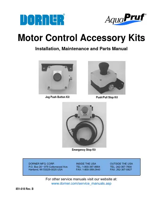
For other service manuals visit our website at:/service_manuals.aspDORNER MFG. CORP .INSIDE THE USAOUTSIDE THE USA P .O. Box 20 • 975 Cottonwood Ave.TEL: 1-800-397-8664TEL: 262-367-7600Hartland, WI 53029-0020 USA FAX: 1-800-369-2440FAX: 262-367-5827851-618 Rev. BMotor Control Accessory KitsInstallation, Maintenance and Parts ManualJog Push Button KitPush/Pull Stop KitEmergency Stop KitDorner Mfg. Corp.2851-618 Rev. BMotor Control Accessory KitsTable of ContentsWarnings – General Safety.................................................. 3Product Description............................................................. 4Jog Push Button Kit......................................................... 4Push/Pull Stop Kit............................................................ 4Emergency Stop Kit......................................................... 4Linking Cable Kit............................................................ 4Installation........................................................................... 5Required Tools................................................................. 5Button Box Kits - Vertical Mounting to Conveyor......... 5Button Box Kits - Horizontal Mounting to Conveyor..... 5Button Box Kits - Stand Mount....................................... 6Wiring (6)Jog Push Button Kit & Push/Pull Stop Kit................... 7Emergency Stop Kit...................................................... 7Linking Cable Kit......................................................... 8Service Parts......................................................................... 9Jog Push Button Kit.......................................................... 9Push/Pull Stop Kit.......................................................... 10Emergency Stop Kit....................................................... 11Linking Kit..................................................................... 12Notes.................................................................................. 13Return Policy. (14)IntroductionUpon receipt of shipment:•Compare shipment with packing slip. Contact factory regarding discrepancies.•Inspect packages for shipping damage. Contact carrier regarding damage.Accessories may be shipped loose.• See accessory instructions for installation.The Dorner Limited Warranty applies.Dorner 7400 Series conveyors have patents pending.Dorner reserves the right to make changes at any time without notice or obligation.Dorner has convenient, pre-configured kits of Key Service Parts for all conveyor products. These time saving kits are easy to order, designed for fast installation, and guarantee you will have what you need when you need it. Key Parts.CAUTIONSome illustrations may show guards removed. DO NOT operate equipment without guards.851-618 Rev. B3Dorner Mfg. Corp.Motor Control Accessory KitsWarnings – General SafetyWARNINGThe safety alert symbol, black triangle with exclamation, is used to alert you to potential personal injury hazards.SEVERE HAZARD!KEEP OFF CONVEYORS. Climbing, sitting, walking or riding on conveyor will cause severe injury.EXPLOSION HAZARD!•DO NOT OPERATE CONVEYORS IN AN EXPLOSIVE ENVIRONMENT. The electric gearmotor generates heat and could ingnite combustible vapors.•Failure to comply will result in death or serious injury.WARNINGController must be properly grounded. Failure to properly ground controller may cause personal injury.SEVERE HAZARD!Hazardous voltage will cause severe injury ordeath. LOCKOUT POWER BEFORE WIRING.WARNINGSEVERE HAZARD!Exposed moving parts can cause severe injury. DO NOT ATTEMPT ADJUSTMENTS WITH CONVEYOR RUNNING. LOCK OUT POWER before removing guards or performing maintenance.WARNINGSEVERE HAZARD!•Dorner cannot control the physicalinstallation and application of conveyors. Taking protective measures is the responsibility of the user.•When conveyors are used in conjunction with other equipment or as part of a multiple conveyor system, CHECK FOR POTENTIAL PINCH POINTS and other mechanical hazards before system start-up.•Failure to comply could result in serious injury.Dorner Mfg. Corp.4851-618 Rev. BMotor Control Accessory KitsProduct DescriptionJog Push Button KitRefer to Figure 1 for typical components.Push/Pull Stop KitRefer to Figure 2 for typical components.Emergency Stop KitRefer to Figure 3 for typical components.Figure 3Linking Cable KitRefer to Figure 4 for typical components.Figure 4Typical Components1Jog Push Button Box 2Drop In T-Bars (x2) 3.50” Spacers (x2)4M6-1.00 20mm Low Head Cap Screws (x2) 5M6-1.00 12mm Low Head Cap Screws (x2)Typical Components1Push/Pull Stop Box 2Drop In T-Bars (x2) 3.50” Spacers (x2)4M6-1.00 20mm Low Head Cap Screws (x2) 5M6-1.00 12mm Low Head Cap Screws (x2)2534142531Typical Components1Cable - 4P Micro Connect 2Wire Ties (x3) 3Drop In T-Bars (x3)4M6-1.00 20mm Low Head Cap Screws (x3) 5Mounting Cable Ties (x3) 6T-Slot Strip Closures (x3) 7Hex Key124537654312Motor Control Accessory Kits Installation InstallationButton Box Kits - Vertical Mounting to Conveyor1.Install t-bars (Figure 5, item 1) into conveyors t-slot.Figure52.Attach button box kit (Figure 6, item 1) to conveyorwith screws (Figure 6, item 2).Figure63.Slide button box kit to its desired mounting locationalong conveyor and tighten both screws.1.Install t-bars (Figure 7, item 1) into conveyor t-slot(Figure 7, item 2).Figure72.Attach button box kit (Figure 8, item 1) to conveyorwith spacers (Figure 8, item 2) and screws (Figure 8, item 3).Figure83.Slide button box kit to its desired mounting locationalong conveyor and tighten both screws.1211123Required Tools 6 mm hex head wrench Button Box Kits - Horizontal Mounting to Conveyor851-618 Rev. B5Dorner Mfg. Corp.Dorner Mfg. Corp.6851-618 Rev. BMotor Control Accessory KitsInstallationButton Box Kits - Stand Mount1.Install t-bar into t-slot.2.Partially thread controller lower mounting bar (Figure 9, item 1) to t-bar with screw (Figure 9, item 2).Figure 93.Install second t-bar into stand t-slot.4.Partially thread controller top mounting bar to t-bar with screw.5.Slide controller to its desired mounting location and tighten both screws.Wiring21SEVERE HAZARD!Hazardous voltage will cause severe injury or death. LOCKOUT POWER BEFORE WIRING.WARNINGSEVERE HAZARD!Exposed moving parts can cause severe injury. DO NOT ATTEMPT ADJUSTMENTS WITH CONVEYOR RUNNING. LOCK OUT POWER before removing guards or performing maintenance.WARNINGController must be properly grounded. Failure to properly ground controller may cause personal injury.Motor Control Accessory Kits InstallationJog Push Button Kit and Push/Pull Stop Kit1.Plug linking cable kit (Figure 10, item 1) into button boxkit (Figure 10, item 2).Figure 102.Connect opposite end of linking cable kit (Figures 11and 12, item 1) to the blue port (Figures 11 and 12, item2) or green port (Figures 11 and 12, item 3) on thecontroller.Figure11Figure12Emergency Stop Kit1.Connect device, 120-volt motor or controller powercord (Figure 13, item 1), into emergency stop receptacle cord (Figure 13, item 2).Figure132.Connect emergency stop power cord to power source.12123212312851-618 Rev. B7Dorner Mfg. Corp.InstallationLinking Cable Kit1.To contain a long run of wiring cable in the conveyor t-slot, use several short lengths of t-slot strip closures(Figure 14, item 1).1Figure142.To route cable over a previously mounted component orto anchor the cable use the mounting cable ties (Figure15, item 1) and single drop-in-t-bars (Figure 15, item 2).Secure with screws (Figure 15, item 3).1321Figure153.Figure 16 shows a typical wire routing or an accessorykit connection to the conveyor using the conveyors t-slot strip closures and wire ties.Figure16Motor Control Accessory KitsDorner Mfg. Corp.8851-618 Rev. B851-618 Rev. B9Dorner Mfg. Corp.Motor Control Accessory KitsInstallationJog Push Button KitItem Part Number Description1201103Mounting Bracket 2677785P Legend Plate3809-314Male Micro Connector 4812-067O-Ring5807-239Push Button Box 6830-210Button Latch7830-211Contact Block Switch-Normally Open8830-213Push Button9639971M Single Drop-In T-bar 10807-1572Spacer11920692M Low Head Cap Screw M6-1.00 x12mm12920694MLow Head Cap Screw M6-1.00 x20mm416375810119212Service Parts Service PartsDorner Mfg. Corp.10851-618 Rev. BMotor Control Accessory KitsInstallation Push/Pull Stop KitItem Part Number Description1201103Mounting Bracket 2201105Legend Plate3809-314Male Micro Connector 4812-067O-Ring5807-239Push Button Box 6830-210Select Switch7830-212Contact Block Switch-Normally Closed8830-214Push Button9639971M Single Drop-In T-Bar 10807-1572Spacer11920692M Low Head Cap Screw M6-1.00 x12mm12920694MLow Head Cap Screw M6-1.00 x20mm519461011283712Service PartsInstallation4126375813151211410914ItemPart Number Description1201103Mounting Bracket 2805-053Receptacle Cord 3805-057Wire Nut 4805-1005Cord Grip5805-655Surface Mounted Relay 6805-805Power Cord7817-243Push Button Box 8830-210Select Switch9830-212Contact Block Switch10830-216Red Push Button11830-217Push Button Nameplate 12639971M Single Drop-In T-Bar 13807-1572Spacer14920692M Low Head Cap Screw M6-1.00 x 12mm15920694MLow Head Cap Screw M6-1.00 x 20mmEmergency Stop KitService PartsInstallationLinking KitItem Part Number Description1639971M Single Drop-In T-Bar 2675232T-Slot Strip Closure 3805-063Wire Tie4805-608Mounting Cable Tie 5807-565Hex Key6809-312 2 meter Micro Cable 809-313 5 meter Micro Cable 7920692MLow Head Cap Screw M6-1.00 x 12mm226371654Service PartsNotes NotesNotes Returns must have prior written factory authorization or they will not be accepted. Items that are returned to Dorner without authorization will not be credited nor returned to the original sender. When calling for authorization, please have the following information ready for the Dorner factory representative or your local distributor:1. Name and address of customer.2. Dorner part number(s) of item(s) being returned.3. Reason for return.4. Customer's original order number used when ordering the item(s).5. Dorner or distributor invoice number.A representative will discuss action to be taken on the returned items and provide a Returned Goods Authorization number for reference.There will be a return charge on all new undamaged items returned for credit where Dorner was not at fault. Dorner is not responsible for return freight on such items.Conveyors and conveyor accessories Standard catalog conveyors30%MPB Series, cleated and specialty belt conveyors 50%7400 & 7600 Series conveyors non-returnable itemsEngineered special products case by caseDrives and accessories 30%Sanitary stand supports non-returnable items PartsStandard stock parts30%MPB, cleated and specialty beltsnon-returnable itemsReturns will not be accepted after 60 days from original invoice date.The return charge covers inspection, cleaning, disassembly, disposal and reissuing of components to inventory. If a replacement is needed prior to evaluation of returned item, a purchase order must be issued. Credit (if any) is issued only after return and evaluation is complete.Dorner has representatives throughout the world. Contact Dorner for the name of your local representative. Our Technical Sales, Catalog Sales and Service Teams will gladly help with your questions on Dorner products.For a copy of Dorner's Warranty, contact factory, distributor, service center or visit our website at .For replacement parts, contact an authorized Dorner Service Center or the factory.Dorner Mfg. Corp. reserves the right to change or discontinue products without notice. All products and services are covered inaccordance with our standard warranty. All rights reserved. © Dorner Mfg. Corp. 2006DORNER MFG. CORP .975 Cottonwood Ave., PO Box 20 Hartland, WI 53029-0020 USA USATEL 1-800-397-8664 (USA)FAX 1-800-369-2440 (USA)Internet: Outside the USA:TEL 1-262-367-7600FAX 1-262-367-5827851-618 Rev. BPrinted in U.S.A.Return Policy。

For other service manuals visit our website at:/service_manuals.aspDORNER MFG. CORP .INSIDE THE USA OUTSIDE THE USA P .O. Box 20 • 975 Cottonwood Ave.TEL: 1-800-397-8664TEL: 262-367-7600Hartland, WI 53029-0020 USA FAX: 1-800-369-2440FAX: 262-367-5827851-260 Rev. J2100, 2200, 4100, 6200 and MPB Series Bottom Mount Drive Package for Light Load60 Hz GearmotorsInstallation Maintenance & Parts ManualDorner Mfg. Corp.2851-260 Rev. J2100, 2200, 4100, 6200 and MPB Series Bottom Mount Drive Package for Light Load 60 Hz Gearmotors Table of ContentsIntroduction......................................................................... 2Warnings − General Safety ................................................. 3Product Description............................................................. 4Specifications...................................................................... 4Installation........................................................................... 7Required Tools................................................................. 7Mounting.......................................................................... 7Preventive Maintenance and Adjustment.......................... 10Required Tools............................................................... 10Timing Belt Tensioning. (10)Timing Belt Replacement .............................................. 10Drive or Driven Pulley Replacement ............................ 11Gearmotor Replacement ................................................ 11Service Parts....................................................................... 142100, 2200, 4100, 6200 Series and MPB SeriesLight Load Bottom Mount Drive Package .................... 144100 Series Adapter Package ........................................ 15Gearmotors..................................................................... 15Return Policy. (16)IntroductionUpon receipt of shipment:•Compare shipment with packing slip. Contact factory regarding discrepancies.•Inspect packages for shipping damage. Contact carrier regarding damage.•Accessories may be shipped loose. See accessory instruc-tions for installation.Dorner 2100 Series conveyors are covered by the following patent numbers: 5131529, 5174435, and corresponding patents and patent applications in other countries.Dorner 2200 and MPB Series conveyors are covered by patent number 5174435 and corresponding patents and patent applications in other countries.Dorner 4100 Series conveyors are covered by patent number 3923148 and corresponding patents and patent applications in other countries.Dorner 6200 Series conveyors are covered by patent number 6685009, 5174435, 6109427 and corresponding patents and patent applications in other countries.Dorner’s Limited Warranty applies.Dorner reserves the right to make changes at any time without notice or obligation.Dorner has convenient, pre −configured kits of Key Service Parts for all conveyor products. These time saving kits are easy to order, designed for fast installation, and guarantee you will have what you need when you need it. Key Parts and Kits are marked in the Service Parts section of this manual with the Performance Parts Kits logo .IMPORTANTSome illustrations may show guardsremoved. Do NOT operate equipment without guards.851-260 Rev. J3Dorner Mfg. Corp.2100, 2200, 4100, 6200 and MPB Series Bottom Mount Drive Package for Light Load 60 Hz Gearmotors Warnings − General SafetyA WARNINGThe safety alert symbol, black triangle with white exclamation, is used to alert you to potential personal injury hazards.Climbing, sitting, walking or riding onconveyor will cause severe injury. KEEP OFFCONVEYORS.DO NOT OPERATE CONVEYORS IN AN EXPLOSIVE ENVIRONMENT.Hazardous voltage will cause severe injury ordeath. LOCK OUT POWER BEFORE WIRING.A WARNINGGearmotors may be HOT.DO NOT TOUCH Gearmotors.A WARNINGExposed moving parts can cause severe injury. LOCK OUT POWER before removingguards or performing maintenance.A WARNINGDorner cannot control the physicalinstallation and application of conveyors. Taking protective measures is the responsibility of the user.When conveyors are used in conjunction with other equipment or as part of a multiple conveyor system, CHECK FOR POTENTIAL PINCH POINTS and other mechanical hazards before system startup.A WARNINGMPB Series Conveyors are not reversible. Reversing creates pinch points which can cause severe injury.DO NOT REVERSE MPB SERIES CONVEYORS.Dorner Mfg. Corp.4851-260 Rev. J2100, 2200, 4100, 6200 and MPB Series Bottom Mount Drive Package for Light Load 60 Hz Gearmotors Product DescriptionRefer to Figure 1 for typical components.Figure 1SpecificationsGearmotor Mounting Package Models:Example:* See “Ordering and Specifications” Catalog for details.A ConveyorB Mounting BracketC GearmotorD Belt TensionerE CoverF Timing BeltG Drive Pulley HDrivenPulleyABCDEFGH Single PhaseDC Variable Speed Output Power 0.03 hp (0.025 kw)0.06 hp (0.04 kw)Input Voltage 115 Volts A.C.130 Volts D.C.Input Frequency 60 Hz N/AFull Load Amperes 0.49 Amperes 0.48 Amperes Gearmotor Ratios15:1 and 36:118:1 and 60:1851-260 Rev. J5Dorner Mfg. Corp.2100, 2200, 4100, 6200 and MPB Series Bottom Mount Drive Package for Light Load 60 Hz Gearmotors SpecificationsTable 2: Belt Speeds for Light Load Fixed Speed Parallel Shaft 60 Hz Gearmotors on 2100, 2200 Gang Drive, 4100 and 6200 Series Conveyors* 115V , 1 phase, non −reversingTable 3: Belt Speeds for Light Load Fixed Speed Parallel Shaft 60 Hz Gearmotors on 2200 Series Conveyors (Excluding Gang Drive)* 115V , 1 phase, non −reversingTable 4: Belt Speeds for Standard Load Fixed Speed Parallel Shaft 60 Hz Gearmotors on MPD Series Conveyors* 115V , 1 phase, non −reversingTable 5: Belt Speeds for Light Load Variable Speed Parallel Shaft DC Gearmotors on 2100, 4100 and 6200 Series Conveyors* 130VDCGearmotors *Belt Speed Drive Pulley Driven Pulley Part Number Gear RatioRPM In-lb N-m Ft/min M/min 62M036PL4FN 36:14236 4.18 2.4223262M036PL4FN 36:14236 4.112 3.7323262M036PL4FN 36:14236 4.117 5.2322262M036PL4FN 36:14236 4.1247.3442262M015PL4FN 15:110015 1.7298.8323262M015PL4FN15:1100151.74112.53222Gearmotors *Belt Speed DrivePulley Driven Pulley Part Number Gear RatioRPM In-lb N-m Ft/min M/min 62M036P L 4FN 36:14236 4.1 134.0283262M036PL4FN 36:14236 4.115 4.6282862M036PL4FN 36:14236 4.121 6.4322262M036PL4FN 36:14236 4.1298.8442262M015PL4FN 15:110015 1.73510.7282862M015PL4FN15:1100151.75516.84428Gearmotors *Belt Speed Drive Pulley Driven Pulley Part Number Gear RatioRPM In-lb N-m Ft/min M/min 62M036PL4FN 36:14236 4.1257.5283262M036PL4FN 36:14236 4.1288.6282862M036PL4FN 36:14236 4.14513.6442862M036PL4FN36:142364.15717.34422Gearmotors *Belt Speed Drive Pulley Driven Pulley Part Number Gear RatioRPM In-lb N-m Ft/min M/min 62M060PLD3DEN 60:142657.4 1.0−8.2.3−2.5223262M060PLD3DEN 60:142657.4 1.4−12.4−3.6323262M018PLD3DEN 18:113921 2.4 4.8−40 1.5−12323262M018PLD3DEN18:1139212.47−582.1−183222Dorner Mfg. Corp.6851-260 Rev. J2100, 2200, 4100, 6200 and MPB Series Bottom Mount Drive Package for Light Load 60 Hz Gearmotors SpecificationsTable 6: Belt Speeds for Standard Load Variable Speed Parallel Shaft DC Gearmotors on 2200 Series Conveyors (Excluding Gang Drive)Table 7: Belt Speeds for Standard Load Variable Speed Parallel Shaft DC Gearmotors on MPB Series Conveyors* 130VDCGearmotors *Belt Speed Drive Pulley Driven Pulley Part Number Gear RatioRPM In-lb N-m Ft/min M/min 62M060PLD3DEN 60:142657.4 1.8−14.5−4.5282862M060PLD3DEN 60:142657.4 2.8−23.8−7442862M018PLD3DEN 18:113921 2.46−49 1.8−15282862M018PLD3DEN18:1139212.49−772.8−234428Gearmotors *Belt Speed Drive Pulley Driven Pulley Part Number Gear RatioRPM In-lb N-m Ft/min M/min 62M060PLD3DEN 60:142657.4 2.3−19.7−5.9223262M060PLD3DEN 60:142657.4 3.4−281−8.6282862M060PLD3DEN 60:142657.4 5.3−44 1.6−13442862M018PLD3DEN 18:113921 2.411−94 3.5−28282862M018PLD3DEN18:1139212.416−1485−454428NOTEFor belt speed other than those listed, contact factory for details.851-260 Rev. J7Dorner Mfg. Corp.2100, 2200, 4100, 6200 and MPB Series Bottom Mount Drive Package for Light Load 60 Hz Gearmotors InstallationRequired Tools•Hex key wrenches: 2.5 mm, 3 mm & 5 mm •Torque wrenchInstallation Component List:Mounting1.Typical components (Figure 2)Figure 22.Locate drive output shaft (Figure 3,item P) and remove two screws (Q).Figure 33.For your reference, the following five figures show the attachment area of complete mounting packages for the various conveyor series.2200 Series Figure 4I Bottom Mount Assembly J Driven Pulley K CoverL M4 Socket Head Screws (4x)M Timing Belt N KeyOM6 Socket Head Screws (2x)A WARNINGExposed moving parts can cause severe injury. LOCK OUT POWER before removing guards or performing maintenance.A WARNINGMPB Series Conveyors are not reversible. Reversing creates pinch points which can cause severe injury. DO NOT REVERSE MPB SERIES CONVEYORS.NOTE6200 conveyor shown, other Series similar.NKMJLOIQPDorner Mfg. Corp.8851-260 Rev. J2100, 2200, 4100, 6200 and MPB Series Bottom Mount Drive Package for Light Load 60 Hz Gearmotors Installation6200 Series Figure54100 SeriesFigure 62100 SeriesFigure 7MPB Series Figure84.Attach mount assembly (Figure 9,item I) with screws (O). Tighten screws to 80 in-lb (9 Nm).Figure95.Install key (Figure 10,item N).Figure 10A WARNINGDrive shaft keyway may be sharp.HANDLE WITH CARE.OIUNJRM851-260 Rev. J9Dorner Mfg. Corp.2100, 2200, 4100, 6200 and MPB Series Bottom Mount Drive Package for Light Load 60 Hz Gearmotors Installation6.Wrap timing belt (M) around driven pulley (J) and drive pulley (R). Install driven pulley (J) onto conveyor shaft.7.Remove cam bearing and spacer (Figure 9,item U). Place the cam bearing and spacer (Figure 11,item U) next to the driven pulley (J). Ensure the flanges of the driven pulley are aligned with the cam bearing. Tighten driven pulley set screws (T). This will allow for proper belt alignment while conveyor is in use. Replace cam bearing and spacer (U).Figure 118.Depending on direction of conveyor belt travel (1 or 2 of Figure 12), position timing belt tensioner (U) as shown. Tension timing belt to obtain 1/8” (3 mm) deflection for 1 lb (456 grams) of force at timing belt mid-point (V). Tighten tensioner screw to 106 in-lb (12 Nm).Figure 129.Install cover (Figure 13,item K) with four (4) screws (L). Tighten to 35 in-lb (4 Nm).Figure 13JT2VU1VUKLLDorner Mfg. Corp.10851-260 Rev. J2100, 2200, 4100, 6200 and MPB Series Bottom Mount Drive Package for Light Load 60 Hz Gearmotors Preventive Maintenance and AdjustmentRequired Tools•Hex key wrenches: 2.5 mm, 3 mm, 5 mm •Straight edge•Screwdriver (for terminal box screws)•Torque wrenchTiming Belt Tensioning1.Remove four (4) screws (Figure 14,item L) and remove cover (K).Figure 142.Loosen tensioner (Figure 15,item U).Figure 15 3.Depending on direction of conveyor belt travel (1 or 2 of Figure 16), position timing belt tensioner (U) as shown. Tension timing belt to obtain 1/8” (3 mm) deflection for 1 lb (456 grams) of force at timing belt mid-point (V). Tighten tensioner screw to 106 in-lb (12 Nm).Figure 164.Install cover (Figure 14,item K) with four (4) screws (L). Tighten screws to 35 in-lb (4 Nm).Timing Belt Replacement1.Remove four (4) screws (Figure 14,item L) and remove cover (K).2.Loosen tensioner (Figure 15,item U).3.Remove timing belt (Figure 17,item M).Figure 17A WARNINGExposed moving parts can cause severe injury. LOCK OUT POWER before removing guards or performing maintenance.KLLUA WARNINGExposed moving parts can cause severe injury. LOCK OUT POWER before removing guards or performing maintenance.2VU1VUTM851-260 Rev. J11Dorner Mfg. Corp.2100, 2200, 4100, 6200 and MPB Series Bottom Mount Drive Package for Light Load 60 Hz Gearmotors Preventive Maintenance and Adjustment4.Install new timing belt.5.Depending on direction of conveyor belt travel (Figure 16,item 1 or 2), position timing belt tensioner (U) as shown. Tension timing belt to obtain 1/8” (3 mm) deflection for 1 lb (456 grams) of force at timing belt mid-point (V). Tighten tensioner screw to 106 in-lb (12 Nm).6.Install cover (Figure 14,item K) with four screws (L). Tighten screws to 4 Nm.Drive or Driven Pulley Replacement1.Complete steps 1 through 3 of “Timing Belt Replacement” section on page 10.2.Loosen set screws and remove drive or driven pulley.Figure 183.Complete steps 6 through 9 of “Installation” section on page 9.Gearmotor Replacement1.For single phase motor, unplug power cord from outlet.2.For DC variable speed motor, unplug motor cord atdisconnect (Figure 19,item W).Figure 193.Remove four screws (Figure 14,item L) and remove cover (K).4.Loosen tensioner (Figure 15,item U).5.Remove timing belt (Figure 17,item M).NOTEIf timing belt does not slide over pulley flange, loosen driven pulley set screws (Figure 17,item T) and remove pulley with belt. For re-installation, see steps 6 through 9 on page 9.A WARNINGExposed moving parts can cause severe injury. LOCK OUT POWER before removing guards or performing maintenance.NOTEIf drive pulley (Figure 18,item R) is replaced, wrap timing belt (M) around drive pulley and complete step 3.RMA WARNINGExposed moving parts can cause severe injury. LOCK OUT POWER before removing guards or performing maintenance.Hazardous voltage will cause severe injury or death. LOCK OUT POWER BEFORE WIRING.NOTEIf timing belt does not slide over pulley flange, loosen driven pulley set screws (Figure 20,item T) and remove pulley with belt (M). For re-installation, see steps 6 through 9 on page 9.Dorner Mfg. Corp.12851-260 Rev. J2100, 2200, 4100, 6200 and MPB Series Bottom Mount Drive Package for Light Load 60 Hz Gearmotors Preventive Maintenance and AdjustmentFigure 206.Loosen two (2) set screws (Figure 21,item T). Remove drive pulley (R).Figure 217.Remove four screws (Figure 22,item X) and detach gearmotor.Figure 228.Mount new gearmotor with four screws (X). Tighten to 45 in-lb (5 Nm).9.Replace drive pulley (Figure 21,item R) and tighten setscrews (T).plete steps 6 through 9 of “Installation” section onpage 9.11.Replace wiring:•For a single phase motor, reverse step 1 on page 11.•For DC variable speed motor, reverse step 2 on page 11.TMRTXNotes2100, 2200, 4100, 6200 and MPB Series Bottom Mount Drive Package for Light Load 60 Hz Gearmotors851-260 Rev. J13Dorner Mfg. Corp.Dorner Mfg. Corp.14851-260 Rev. J2100, 2200, 4100, 6200 and MPB Series Bottom Mount Drive Package for Light Load 60 Hz Gearmotors Service Parts2100, 2200, 4100, 6200 Series and MPB Series Light Load Bottom Mount Drive PackageNOTEFor replacement parts other than those shown in this section, contact an authorized Dorner Service Center or the factory. Key Service Parts and Kits are identified by the Performance Parts Kits logo . Dorner recommends keeping these parts on hand.Item Part Number Description1202390M Nut, Cam Follower2450027M Drive Spacer (2100 − Cleated Belt andall 6200)450377MDrive Spacer (2100, 2200 and MPB − Flat Belt and all 4100)3450047M Cover Mounting Bracket (Flat Belt)450375MCover Mounting Bracket (Cleated Belt and MPB)4200376M Drive Guard (Flat Belt)450376M Drive Guard (Cleated Belt and MPB)5450046M Light Duty Motor Mount Plate − Short (Flat Belt, except MPB)450026MLight Duty Motor Mount Plate (Cleated Belt and MPB)6450445Spacer 7802−046Bearing8807−226Snap −out Plastic Plug9807−952Groove Pin (Used with Item 2 Only)10920545MSocket Head Screw M5x45mm − 15:1 Gearhead (Fixed Speed Gearmotor Only)920555MSocket Head Screw M5x55mm − 36:1 Gearhead (Fixed Speed Gearmotor Only)920416MSocket Head Cap Screw M4x16mm(Variable Speed Gearmotor Only)11980422M Square Key .4mm x 22mm (Fixed Speed Gearmotor)912−084Square Key .125” x .75” (Variable Speed Gearmotor)12920406M Socket Head Screw M4 x 6mm 13920408M Socket Head Screw M4 x 8mm 14920625M Socket Head Screw M6 x 25mm (2100)920622M Socket Head Screw M6 x 22mm (2200 Cleated Belt)920618M Socket Head Screw M6 x 18mm (4100)920630MSocket Head Screw M6 x 30mm (2200 Flat Belt and all 6200)15920840M Socket Head Screw M8 x 40mm 16980422M Square Key 4mm x 22mm 912−084Square Key .125” x .75” (1” Wide Conveyor − 4100 Only)17814-105Timing Belt, 15mm W x 460mm L 814-065Timing Belt, 15mm W x 475mm L 814-101Timing Belt, 15mm W x 500mm L 814-108Timing Belt, 15mm W x 520mm L 18450366MP Driven Pulley, 22Tooth, 12mm bore 450367MP Driven Pulley, 28Tooth, 12mm bore 450368MPDriven Pulley,32Tooth, 12mm boreItem Part Number Description851-260 Rev. J15Dorner Mfg. Corp.2100, 2200, 4100, 6200 and MPB Series Bottom Mount Drive Package for Light Load 60 Hz Gearmotors Service Parts4100 Series Adapter PackageGearmotors19450384MP Drive Pulley, 22T ooth, 10mm bore 450385MP Drive Pulley, 28T ooth, 10mm bore 450386MP Drive Pulley, 32T ooth, 10mm bore 450387MP Drive Pulley, 44T ooth, 10mm bore 450556P Drive Pulley, 22T ooth, 0.5” bore 450556P Drive Pulley, 28T ooth, 0.5” bore 450556P Drive Pulley, 32T ooth, 0.5” bore 450556PDrive Pulley, 44T ooth, 0.5” boreItem Part No.Part Description1609486Mounting Block 1” (25mm)609487Mounting Block 2” (51mm)609488Mounting Block 3” (76mm)609479Mounting Block 4” (102mm)609480Mounting Block 5” (127mm)609481Mounting Block 6” (152mm)609482Mounting Block 7” (178mm)609483Mounting Block 8” (203mm)609484Mounting Block 10” (254mm)609485Mounting Block 12” (305mm)2613602P Bolt & Flat Washer Assembly 3450374Drive Adapter Plate 4910−126Hex Nut with Lock Washer 5930612MFlat Head Screw M6 x 12mmItem Part NumberDescriptionItem Part No. Part Description162M036PL411FN Gearmotor, 0.03 hp, 115 Volts, 42RPM, 60 Hz, 1-Phase, 36:162M015PL411FNGearmotor, 0.03 hp, 115 Volts, 100 RPM, 60 Hz, 1-Phase, 15:162M060PLD3DEN Gearmotor, 0.06 hp, 130 Volts, 42 RPM, DC, 60:162M018PLD3DEN Gearmotor, 0.06 hp, 130 Volts, 139 RPM, DC, 18:12980422M Key, 4mm x 22mm, 10mm Bore 912−052Key, 1/8” x 5/8”, 1/2” Bore851-260 Rev. J Printed in U.S.A.Dorner Mfg. Corp. reserves the right to change or discontinue products without notice. Allproducts and services are covered inaccordance with our standard warranty. All rights reserved. © Dorner Mfg. Corp. 2006DORNER MFG. CORP.975 Cottonwood Ave., PO Box 20 Hartland, WI 53029-0020 USAUSATEL 1-800-397-8664 (USA)FAX 1-800-369-2440 (USA)Internet: Outside the USA:TEL 1-262-367-7600FAX 1-262-367-5827Return PolicyReturns must have prior written factory authorization or they will not be accepted. Items that are returned to Dornerwithout authorization will not be credited nor returned to the original sender. When calling for authorization, please have the following information ready for the Dorner factory representative or your local distributor:1. Name and address of customer.2. Dorner part number(s) of item(s) being returned.3. Reason for return.4. Customer's original order number used when ordering the item(s).5. Dorner or distributor invoice number.A representative will discuss action to be taken on the returned items and provide a Returned Goods Authorization number for reference.There will be a return charge on all new undamaged items returned for credit where Dorner was not at fault. Dorner is not responsible for return freight on such items.Conveyors and conveyor accessories Standard catalog conveyors 30%MPB Series, cleated and specialty belt conveyors 50%7400 & 7600 Series conveyors non-returnable items Engineered special products case by case Drives and accessories 30%Sanitary stand supports non-returnable items PartsStandard stock parts30%MPB, cleated and specialty beltsnon-returnable itemsReturns will not be accepted after 60 days from original invoice date.The return charge covers inspection, cleaning, disassembly, disposal and reissuing of components to inventory. If a replacement is needed prior to evaluation of returned item, a purchase order must be issued. Credit (if any) is issued only after return and evaluation is complete.Dorner has representatives throughout the world. Contact Dorner for the name of your local representative. Our Technical Sales, Catalog Sales and Service Teams will gladly help with your questions on Dorner products.For a copy of Dorner's Warranty, contact factory, distributor, service center or visit our website at .For replacement parts, contact an authorized Dorner Service Center or the factory.。
DKL制动逻辑控制装置使用维修手册前言本产品在出厂前已经过严格检查。
DKL装置购入后,请检查本产品是否因运输不慎而造成损伤;产品的规格、型号是否与订购产品的机种相符;有无合格标志等。
如有问题,请与本公司或供应商联系。
本产品的保修期依照标书约定。
若由于下述原因引起的故障,不属于保修范围:●不正确的操作或未经允许自行修理及改造所引起的问题。
●超出标准规范或未经允许自行修理及改造所引起的问题。
●购买后跌损、野蛮搬运、未按本说明书要求使用造成的问题。
●因环境不良所引起的器件老化或故障。
●为确保设备的良好运行,禁止非专业人员随意打开机箱。
专业人员进行维修时要注意确保人身安全。
目录一、概述二、装置构成三、主要技术参数四、工作原理五、安装与接线六、使用与维护七、故障检修八、附录:各车型接口线号及梯形图一、概述DKL制动逻辑控制装置为电空制动机的电路集成控制装置,尤其适用于DK1制动机控制系统。
该装置采用先进表面贴片(SMT)技术与逻辑控制芯片相结合,取代原制动系统中的迂回电路、阻流板、时间继电器与中间继电器,具有反应速度快、可靠性高、抗干扰能力强、结构紧凑、检修方便等特点;而且具备通过调整软件在相同的硬件上实现不同的逻辑组合功能,以达到控制不同的车型之目的。
DKL制动逻辑控制装置外形图如图一所示。
(此为DKL-SS4G,其它型号类似)图一、DKL制动逻辑控制装置外形图二、装置构成DKL制动逻辑控制装置采用欧式4U标准结构框架,并采用20芯铁路专用连接器实现与机车的信号通讯。
DKL装置(为叙述方便,将DKL制动逻辑控制装置简称为DKL装置)结构图如图2所示。
图二、DKL装置结构图DKL制动逻辑装置由四个部分组成,分别为固定基架、DKL电源板、DKL控制板和DKL输出板。
DKL装置构成外形图如图三所示。
在固定基架前面板部,安装有钮子开关;对应制动系统功能开关,其定义和对应关系见附录。
基架后侧,装有20芯连接器插座,型号:TL02J20ZY;用于实现同外部机车信号联系。
电动推杆安装、使用、维护说明书北京金达凯诺传动设备有限公司前言本说明书与产品密不可分,内含有关推杆正确安装,使用以及维护的基本知识。
对于未按照技术目录上的说明对推杆进行的不正确操作而导致的直接或间接后果金达凯诺公司不承担任何责任。
不按照说明书的说明进行使用维护操作违反保修的条款,由此而引发的可能的人员伤亡或产品的损坏,金达凯诺公司不承担任何责任。
在产品选形以及产品设计过程中,金达凯诺公司以及它制定的代理商随时为您服务,并为你正确应用推杆提供所有的技术支持。
金达凯诺公司有权在不做任何通知的情况下,对产品及说明书进行完善和修改。
安全说明安装前详细阅读操作说明书遵守相关的安全指示说明,说明如下:电压危险带电工作机械危险推杆和车间可能受损坏,操作人员有危险非常重要的指令注意留心.总论电动推杆是将电能转换为机械能,由电动机的旋转运动转换为直线推拉运动的一种电动执行机构。
其工作情况类同于广泛应用的液压、气动执行机构。
电动推杆结构紧凑,性能可靠,体积小,重量轻,噪音低,安装调试、使用维修方便,还可以加装手动机构,便于安装调试。
电动推杆具有额定推力过载保护装置和行程调节机构。
用户可在额定行程范围内任意调节工作行程。
一、电动推杆的形式金达凯诺公司为用户提供了如下形式电动推杆1、FD系列小型电动推杆2、DL系列电动推杆3、DG系列重型电动推杆二、电动推杆的选择1、电动推杆结构形式的选择根据用户使用设备具体结构,由用户自行确定,或与厂商办事处协商。
2、电动推杆安装形式的选择根据用户使用设备具体结构,由用户自行确定,或与厂商办事处协商。
3、电动推杆额定推力的选择根据用户使用设备具体结构,由用户自行确定,或与厂商办事处协商。
4、电动推杆额定行程的选择根据用户使用设备具体结构,由用户自行确定,或与厂商办事处协商。
5、电动推杆额定速度的选择根据用户使用设备具体结构,由用户自行确定,或与厂商办事处协商。
三、电动推杆电器原理及接线图1、接线盒中的接线——三相电机的接线方式参见厂家接线盒中的标示决定三角形或星形接法。
DL-582P 云热敏票据打印机DL-582Y171615151412121111111010109987655521173.4.1 打印机自检4.1 打印机不工作第4章 故障处理声明目 录安全须知第1章 产品简介1.1 简介1.2 主要特点1.3 开箱清单1.4 外观及组件1.5 产品尺寸2.1 技术规格2.2 打印耗材技术指标2.3 打印及切纸位置3.1 安装纸卷3.2 电源连接3.3 指示灯的说明3.4 打印测试2.2.1 连续纸参数2.2.2 用纸注意事项2.3.1 打印位置2.3.2 切纸位置第2章 产品规格第3章 安装和使用1718191919204.2 状态指示灯4.3 打印过程中出现的问题5.1 清洁打印头5.2 清洁传感器、胶辊和纸张路径第5章 清洁打印机附录1:电子信息产品污染控制的说明本手册于2020年印制,版权属于得力集团有限公司中国印制。
1.0版本。
DL-582P/DL-582Y是一款云热敏票据打印机。
具有高打印质量,高速度,高稳定性等特点,可广泛应用于餐饮外卖行业,商超零售行业,票据订单业务,电商等需要接单,打单的场合。
1)噪音小,打印快,接单稳定2)方便快捷更换卷纸3)使用简便,自动接单4)用户系统自定义设置,展现店铺视觉宣传打印机电源适配器使用说明书卷纸图1-3-1开机键(长按)菜单下移键网络指示灯状态指示灯电源线连接口网线连接口(无效接口)流量卡卡槽(无效接口)工厂配置连接口图1-4-1“设置菜单”键(短按)“WiFi设置”菜单快捷键(长按)菜单确定键图1-5-1140.884.5112.6开盖手指着力处连接端向下热敏面向外1.打印机填装打印纸时,卷纸方向应按照下图所示进行填放。
2.将卷纸的外圈纸撕开,并将连接端向下,热敏面朝外,如图示:图3-1-1图3-1-23.将卷纸拉出一段贴靠在出纸口正中,并按纸仓盖中间区域关闭纸仓盖,如图示:图3-1-34.撕掉多余纸张,如图示:图3-1-43.3 指示灯的说明初始安装打印机或打印机存在任何问题是可以执行自检程序“关于本机”,确认如下状态:1)确认已正确连接电源,正确放置打印纸;2)确认打印机处于关机状态,且顶盖已合盖到位;3)长按左键开机,开机后,按右键进入设置菜单,然后进入“关于本机”。
创维集团有限公司研究院警告本手册仅供有经验的维修人员使用,不适用于一般消费者,手册中没有对非技术人员企图维修本产品而存在的潜在危害提出警告或提醒。
电器产品应由有经验的专业技术人员进行维护和修理,任何其它人企图对本手册涉及的产品进行维护和修理将有可能受到严重伤害甚至有生命危险。
1 产品综述1.1 机芯概述8K93机芯是是我们公司与台湾MTK公司合作开发的主要面向大尺寸的高端LCD 3D电视,采用MT5326ACDJ芯片,内置双核的ARM Cortex-A9 900MHz CPU,芯片集成度高,采用单芯片,功能强大,操作系统采用最新的Android 4.0,支持3D ME/MC,支持DTMB,支持HDMI1.4a,USB2.0,支持语音输入功能,内置WIFI。
8K93机芯具有电路设计简洁,功能强大,性能优良和通用性强,工艺设计和成本设计较合理等优点,是目前公司面向高端的智能云电视。
1.2 主要功能1、Android 4.0操作系统。
2、丰富的接收功能。
3、应用商城,在线酷影,搜索、壁纸、任务管理,设置,网址导航,云平台,云健康,健康运动,媒体播放,酷开商场,我的酷开等功能。
4、三屏互动功能。
5、健康屏变功能。
6、屏稳功能。
7、矩阵背光功能。
8、语音博士功能。
9、第三代六基色彩色图像处理技术。
10、3D ME/MC处理技术(功能可选)。
12、内置WIFI功能(功能可选)。
13、数字一体机(功能可选)。
1.3 主要技术规格1、一路模拟电视,一路DTMB输入,两路视频输入,一路分量输入,一路电脑输入,三路HDMI输入,四路USB输入,两路模拟音频输入,一路SD卡输入,一路CA卡DTV输入。
2、支持*.mpg,*.rm,*.rmvb,*mp4,*.VOB,*.DAT,*.AVI,*.VID等格式的影片文件;支持*.mp3,*.wma 等格式歌曲;支持JPEG/PNG/BMP/JIF等格式图片;3、分量/HDMI 支持480I,480P,576I,576P,720P50,720P60,1080I50,1080I60,1080P50,1080P60全高清格式4、支持两路serial flash,支持一路NAND flash.5、支持HDMI 1.4a 3D DTV输入格式,支持MPEG Decoder(MVC)3D DTV输入格式,支持Reald 3D,Sensio 3D,Frame sequential 3D,Line_interlerleave 3D。
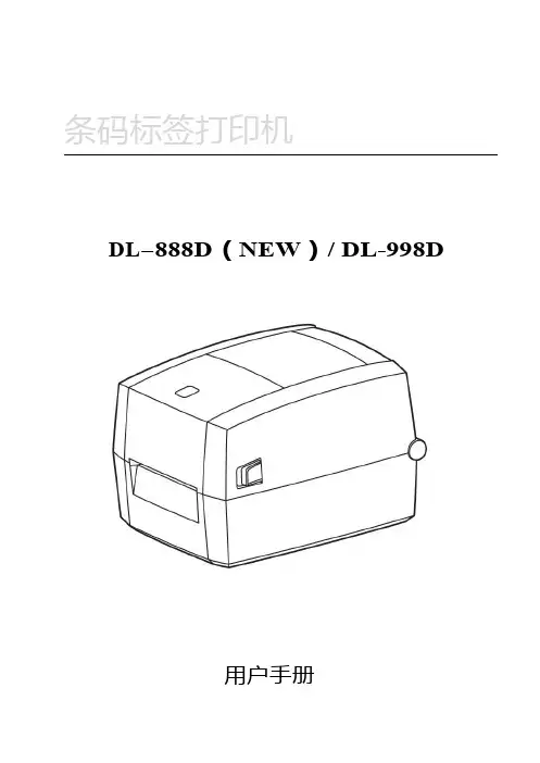
条码标签打印机DL-888D(NEW)/DL-998D用户手册目录手册信息 (1)安全须知 (2)第1章产品简介 (6)1.1开箱清单 (6)1.2外观及组件 (7)1.3产品尺寸 (8)第2章产品规格 (9)第3章安装和使用 (11)3.1安装介质 (11)3.2电源连接 (14)3.3接口连接 (15)3.4标签侦测 (16)3.5操作界面说明 (17)3.6基本功能使用 (19)3.6.1打开/关闭电源 (19)3.6.2打印测试 (19)3.6.3标签学习 (20)3.6.4首张回退 (20)第4章接口 (21)第5章清洁打印机 (22)5.1清洁打印头 (22)5.2清洁传感器、胶辊和纸张路径 (23)手册信息本用户手册包含产品使用、安装等基本信息。
以下手册对各种技术问题和领域有更为详细的介绍。
版本:1.01安全须知在操作使用打印机之前,请仔细阅读下面的注意事项,以免发生人身伤害或设备损坏。
1.安全警告标志——警告:必须遵守,以免伤害人体,损坏设备。
——注意:给出了打印机操作的重要信息及提示。
2.安全注意事项警告:违反以下事项可能会导致严重的伤亡事故。
1)不要同时将几个插头插入一个多孔电源插座中。
•这会导致过热和火灾。
•如果插头潮湿或者肮脏,请在使用前烘干或者擦拭干净。
•如果插头与电源插座不配套,请不要插上电源。
•只能使用标准化的多孔电源插座。
2)您只能使用本包装中供应的适配器。
•使用其它适配器十分危险。
3)不要通过拉扯连接线的方式拔插头。
•这可能损坏连接线,造成火灾或者打印机故障。
4)不要在手潮湿的时候,插或者拔电源插头。
•这可能导致触电。
5)不要用力弯曲连接线,或者将其置于重物之下。
•连接线损坏后,可能造成火灾。
注意:违反以下事项可能造成轻伤或损坏设备。
1)如果发现打印机不明原因地冒烟、发出气味或者噪音,请拔下插头,再采取急救措施。
•关闭打印机,拔下设备的插头。
•在烟消失后,电话联系经销商进行维修。
夏普全系列维修手册夏普全系列维修手册进入维修代码方式进入工厂代码方式SF1118/1025/AR161/AR200C 插入0 插入 C Ca 0 CAR275/AR255# 插入 C 插入# 插入0 CM350/M450P * C * P * 0 CAR158C 浓度 C 浓度 C 浓度 C 倍率AR2818 m160 m205 m276# 插入 C 插入* 插入CA 插入夏普便携复印机鼓计数清零方法1、按曝光开机,现在除准备灯外所以指示灯都会点亮2、按住曝光约十秒钟直到三个灯同时点亮,松开曝光3、重新开机故障代码U(主板电池电压低) L(原稿台未回到规定位置)H(热辊定影器故障) F(暴光灯或定影灯温度保险断掉)维修方式:按清除键-重复键-加法键-减法键进入1 解除故障2 读出主计数器内容3 读出总计数器内容4读出维修计数器内容5 维修计数器复位`夏普模拟复印机维修代码维进:C-插入- 0-插入或清除键-插入键-0键-插入键-清除键厂进:C- Ca - 0- C 纸盒键按4秒进用户模式1-01:反光镜动作检测1-02:光学系统传感器检查(缺纸灯、卡纸灯)1-03:镜头动作检查1-04:镜头动作老化检查2-01:ADF进行原稿输送动作2-02:ADF传感器检查2-03:ADF单独装纸动作检查(给纸电机反向旋转)2-04:ADF单独装纸动作检查(给纸电机正向旋转)2-05:ADF单独装纸动作检查(输纸电机正向旋转)2-06:ADF单独装纸动作检查(输纸电机反向旋转)2-07:ADF单独装纸动作检查(原稿限位器电磁阀接通)2-08:ADF单独装纸动作检查(送纸限位器)2-10:ADF单独装纸动作检查3-02:分页器传感器检查3-03:分页器单独装纸动作检查(输纸电机)3-04:分页器单独装纸动作检查(纸库电机)3-05:分页器单独装纸动作检查(蜂鸣器)3-06:分页器单独装纸动作检查(直线马达)(只适用于SF-S54)3-07:分页器单独装纸动作检查(钳夹马达)(只适用于SF-S54)5-01:操作面板显示检查(LED灯全亮5秒)5-02:加热灯检查(以0.5秒间隔亮灭加热灯)5-03:复印灯点亮检查5-04:DL 光度检查(放电灯亮30秒)5-05:BL 光度检查(消电灯以5秒间隔亮灭)6-01:输纸系统装纸动作(离合器/ 电磁阀)通断30次6-02:给纸电机动作检查(仅SP-2118)6-10:主纸盒半圆辊动作7-01:预热时间显示和老化预热计时并显示(秒)7-04:预热省略7-06:间歇老化7-08:预热时间显示8-01:显影偏压输出(30秒)8-02:主/ 转印充电输出/ 栅极检查(ME)8-03:主/ 转印充电输出/ 栅极检查(PE)8-04:主/ 转印充电输出/ 栅极检查(T / S)8-07:分离充电器输出(30秒)9-02 ADU传感器检查测试指令9-05 门电磁铁启动10 :色粉电机转动14 :故障消除(除U2故障外)15 废色粉装满(小人灯闪亮)取消16 U2 故障取消17 消除PF故障20-01 保养计数器(小人灯亮)清零21-01 保养周期设定0=50000张1=2500张2=5000张3=10000张4=25000张5=关闭21-02 显影器小修设置0=80000张1=5000张2=10000张21-03 彩色显影器小修设置0=10000张1=5000张22-01:保养计数器显示22-02:保养预置计数器显示22-03:卡纸存储器显示22-04:总卡纸存储器显示22-05:总计数器显示22-06:DV 计数器显示22-07:DV 预置计数器显示(载体更换周期)22-08:ADF 送纸数显示22-10:装订计数显示22-15:故障记忆显示(显示最近20个错误代码)24-01:卡纸存储器/ 总卡纸计数器清零24-02:故障记忆清除24-04:ADF 计数器清零24-05:装订计数清零24-06:显影剂调整时间清零24-07:鼓调整时间清零24-06:纸盒计数器清零25-01:主驱动系统检查25-02:自动显影剂调整(更换载体后执行)(厂代中80-2调浓度与漏粉)26-01:选购件设定(输入选购件所表数值之和)26-05:计数器方式设定( 0 A3计数 3 A4计数)26-06:目的地设定(设为10)26-07:转鼓灵敏度设定校正复印灯电压(1-3 初始为2)26-10:AE 原稿浓度设定(1低浓度原稿2正常浓度原稿)26-13:预热方式设定(0 正常1主电机转至预热结束)26-20:后缘空白设定(0 有空白1无空白)26-29:交流电压调整(0 100V 1 200V)30-01:复印机传感器检查(纸检测)42-01:清除小太阳符号换载体后43-01:定影温度设定(倍率键选择)44-01:成像控制动作设定(输入校正方式代码总和,栅压校正+1 光学尘埃校正+2 鼓磨损校正+4)44-05:栅极电压较正(显示图介浓度传感器A/D输入值)44-06:栅极电压较正强行执行44-07:图像浓度/ 转鼓标记传感器动作试验(F-J中0表示鼓标不能检测,1表示能检到)44-08:成像控制数据显示44-09:成像控制数据显示(最新值)44-10:栅极电压较正(转鼓表面/ 斑纹)数据显示44-11:初级栅极偏压设定44-12:中央控制处理器关闭时对复印功能进行检测主代码子代码内容46-01:曝光调整47 :AE 传感器增益自动调整(先在稿台上放几张A3白纸)48-01:前/ 后(垂直)放大倍率调整(A值调100% B调200% C调50%)48-02:输纸方向放大倍率调整(反光镜速度校正)50-01:复印件前缘调整50-02:前缘调整(简单型)(C值为245 显示为A45)51-02:阻力量调整(A 托盘阻力B手动给纸)53-01:ADF 停止位置调整值(普通纸)设定53-03:ADF 停止位置调整值(薄纸)设定53-04:ADF 阻力传感器、宽度传感器调整53-05:ADF出纸传感器调整53-06:ADF 时间传感器调整54-03:除去蜂鸣装置57 删边量调整58 -1 纸头调整58-2 空白区调整60 原稿尺寸检测97 补粉夏普模拟复印机故障代码L1-00:反光镜进给故障(传感器坏、主板坏、反光镜传动索缺油)L3-00:反光镜返回故障L4-01:主电机故障L5-00:镜头初始误差检测L5-02:镜头故障L5-03 第4/5反光镜电机故障L5-04 第4/5反光镜电机MHPS故障L5-05 镜头电机故障L5-06 镜头原位检测出错L5-8 镜头原位传感器故障L6 加粉电机故障L8-01:零交叉脉冲故障L8-03:AE传感器故障(执行47时,AE输入无变化)L9 分页器故障H2-00:定影热敏电阻开路故障(热敏电阻输入超过3.81V)H3-00:定影高温故障(定影温达240度,热敏电阻输入在0.36V下) H4-00:定影低温故障U1 存储器电池电压底于2.2V,指令“13”,复位U2-01:后备储存器故障U3-8 镜架驱动电机检测异常U3-10 镜架原位传感器故障U3-20 反光镜电机锁定U3-21 反光镜原始位置出错U3-40 时钟脉冲故障U4-02 ADU对位板操作错误检测U4-04 ADU后端板故障U5-00:ADF通信错误U5-01:A马达错误检测U5-03 时序传感器故障U5-04 空传感器故障U5-11:给纸电机故障U5-12:输纸电机故障U6-00:机架通信错误U6-01:1纸盒电机错误U6-02:2纸盒电机错误U6-03:3纸盒电机错误U6-08:机架24V线路出错U6-10:机架送纸电机错误U6-09:机架LCC电机过电流检测F1-00:分页器通信错误F1-02:输纸电机故障F1-04:纸库上限/下限故障F1-05:纸库原位传感器故障F1-06:纸库电机故障F1-14:输纸电势故障F2-02:色粉粉斗电机错误F2-31:图象浓度传感器故障(传感器脏、删边灯脏、鼓处插线坏)F2-32:鼓标记传感器故障F2-35:栅级电压校正故障F3-12 上纸盒升起电机故障F3-22 下纸盒升起电机故障C2 高压发生器故障电极丝短路或断路CC 原稿尺寸传感器误检测EE-EU:色粉不足EE-EL:色粉过多CH:亮是盖打开闪烁是显影组件安装不到位夏普数码复印机维修代码1-1 确认反射镜装置动作1-2 确认光学系传感器动作1-6 反光镜扫描连续动作2-1 SPF连续动作2-2 确认SPF传感器动作2-3 确认SPF电动机正转方向动人2-4 确认SPF电动机逆转方向动作2-8 确认SPF进纸电磁阀动作2-9 RSPF翻转电磁铁动作检查2-10 RSPF出纸门电磁铁动作检查2-11 确认SPF PS释放电磁阀动作3-2 确认移动分离传感器动作3-3 确认分页器移动动人3-4 确认分离板动作(检测是否正常转动)3-11 确认配页器原位动作5-1 确认扣作部显示(面板LED灯全亮秒)5-2 确认加热灯亮(定影灯50秒间隔亮5次)5-3 确认复印机灯亮(10秒浓度键改亮度)6-1 确认进纸电磁阀动作(50秒间隔驱动20次)6-10 驱动主盒半圆辊7-1 预热时间表示有JAM老化7-4 预热省略7-6 间歇老化有纸7-8 预热时间表示8-1 复印模式的显影偏压输出8-2 复印模式的主充电器栅极电压(High状态高)输出8-3 复印模式的主充电器栅极电压(Low状态低)输出8-6 转印电压输出8-10 打印模式的显影偏压以及控制回路的动作确认和调整8-11 打印模式的主充电器栅极电压(High状态)以及控制回路的动作确认8-12 打印模式的主充电器栅极电压(Low状态)以及控制回路的动作确认8-13 FAX模式的显影偏压以及控制回路的动作确认和调整8-14 FAX模式的主充电器栅极电压(High状态)以及控制回路的动作确认8-15 FAX模式的主充电器栅极电压(Low状态)以及控制回路的动作确认9-1 双面器负载(马达)正转测试9-2 双面器负载(马达)反转测试9-4 双面器马达的转速调整9-5 双面器马达的把向转换时间调整10 确认墨粉电动机动作14 解除U2以外的故障16 解除U2故障20-1 清除保养计数21-1 保养循环的设定(0=2500张1=5000张2=15000张3=30000张4=150000张5=999999张)22-1 保养计数器的显示22-2 保养预置值显示(SIM20-1设定值)22-3 卡纸储存的显示(最近30次卡纸)22-4 总卡纸计数显示22-5 总计数显示22-6 显影计数器显示22-8 SPF计数器显示22-9 进纸计数器显示22-12 光鼓计数器显示22-13 CRUM类型显示22-14 FLASH ROM的版本22-15 故障储存器显示(最近15次故障)22-16 双面打印计数显示22-17 复印计数器显示22-18 打印计数器显示22-19 电子分类计数器显示22-21 扫描计数器显示22-22 SPF卡纸计数器显示24-1 卡纸储存器清除24-2 故障储存器清除24-4 SPF计数器清除24-5 双面打印计数清除24-6 进纸计数器清除24-7 光鼓计数器清除24-8 复印计数器清除24-9 印刷计数器清除24-10 电子类计数器清除24-13 扫描计数器清除24-14 SPF卡纸计数清除24-15 扫描模式计数器清除25-1 确认主电机机劝作(30秒)25-10 确认LSU多面镜电动机动作(30秒)26-1 选件开关的显示(选购件对应灯亮)26-3 部门管理器的设定(0:计数模式1:投币模式)26-4 本机双面动作设置(0:无双面1:有双面功能)26-5 计数器方式设定(0:双面计数1:单面计数)26-6 发送地设定(5:中国6:台湾)26-7 直接显示CPM旋转速度26-10 网络扫描的试用设定26-18 节粉方式(0:节粉关闭1打开)26-22 语言设定(打印卡面板语言)(0:日语1:英语……)26-30 CE标记对应控制设定(0:CE标记OFF 1:ON)26-32 风扇旋转状况变化26-36 (0:保养计数到停机1:不停)26-37 (0:载体计数到停机1:不停)26-38 光鼓超寿命停止设定(0停机1不停机)26-39 内存容量检测(16:16M内存32:32M内存)26-42 转印时间调整(R系列:1:240MS 3:260MS 9:320MS)(M系列机子取值1-99 默认值50)26-43 上下端空白设置(自动灯表下端,手动灯表上端)26-50 黑白转换功能设定(0:可转1:不可转)26-51 复印机暂停功能设定(0:不停1:停)26-60 未装载FAX时,设定FAX模式键是否有效27-1 设定有元PC/调制解调器的通信故障27-5 输入机器的机号30-1 确认本体传感器动作30-2 确认给纸部的传感、检测器及相关回路的动作40-1 确认手动托盘的纸张尺寸检测器及相关回路的动作41-2 调整OC原稿检测传感器41-3 原稿检测传感器受光电平显示41-4 OC盖板20度时的检测电平调整42-1 载体记数清除43-1 定影温度设定(倍率键调)43-10 明信片纸张进纸周期设置(取值1-99)43-11 明信片纸定影温度设置43-12 待机模式定影风扇转动设置(0:低速1:高速)43-13 定影纸张间隙控制(0:禁止1:允许)44-34 转印电流设定44-40 墨粉补充前转动时间设置(取值1-99)46-1 复印浓度300dpi电平调整46-2 复印曝光600dpi浓度等级调整46-7 分别调整复印曝光浓度等级(超级照片)46-9 复印浓度等级单独调整手动300dpi等级(文字)46-10 复印浓度等级单独调整手动600dpi(文字/照片)46-11 复印浓度等级单独调整(照片)46-18 复印对比度调整300dpi46-19 曝光时的图像质量调整46-20 SPF的曝光浓度校正46-29 复印对比度调整600dpi46-30 进行AE设定(取值0-30)46-31 图像锐度调整(0:黑白校正2:清晰)46-39 调整传真模式对比度46-45 调整传真模式的图像浓度48-1 主(前后)扫描方向倍率调整48-2 复印时OC方式副扫描方向倍率调整48-3 自动调整前端.副扫描倍率48-5 复印时SPF方式副扫描方向倍率调整49-1 FLASH ROM程序写入模式50-1 复印画像位置调整(左右方向,值加减1移动0.127MM)50-5 调整图像先端位置50-6 调整复印模式SPF/RSPF原稿图像位置50-10 用纸中心偏移调整(上下方向)50-12 调整复印模式原稿图像中心位置50-13 OC方式原稿中心偏50-16 SPF方式原稿中心偏听偏信移调整50-18 双面复印时反面图像位置调整50-19 双面复印时后端空白调整51-02 对位量调整51-8 设定禁止感光鼓分离爪动作53-8 SPF扫描位置调整56-1 传送MFP控制器数据61-1 检测LSU的动作61-2 调复印模式激光功率(绝对值)61-3 六棱镜电机检测62-1 格式化硬盘62-3 检测硬盘读写操作62-8 格式化硬盘(除系统数据区域)62-10 删除完成作业列表(同时删除作业日志)63-1 确认黑白校正数据63-2 执行黑白校正63-7 自动调整SPF白校正开始的像素位置64-1 自我打印功能65-5 进行操作面板的检测66-22 调传真听筒音量66-23 下载传真程序66-24 清除传真数据内存66-39 设定发货地规格66-60 设定ACR数据67-11 用于设定“select-in“信号67-14 进行flash programs写入/比较检测67-17 进行NVROM的清除67-18 清除FLASH ROM 的Network Scanner Application(网络扫描应用软件)用数据区域67-20 装载网络扫描组件时,检测网络连接夏普数码复印机故障代码H2 00 热敏电阻断开(电阻到MCU板的连接、SIM14清)H3 00 定影部高温故障(温超240度、SIM5-2灯闪时:查接线。
DS1121信号电平表(电视场强仪)使 用 说 明 书Ver.1.3天津市德力电子仪器有限公司制造天津市南开区宜宾道40号 (300113)服务电话:(022)27631088,27631288传 真:(022)27645002公司主页:电子邮件:deviser@标准附件专供充电电源:DS10012充电器1个射频输入接头:F型 1个使用说明书: 1本保 修这台仪器售出后保修十八个月,生产商或代理商负责必要的调校或检验工作,仪器经校准检验合格后才装箱,发还给用户。
用户的职责是:按照说明书来使用这台仪器,假如要维修,就把它送往本公司或指定代理维修站。
一般说来于保修期内,一切非人为使用不当的故障,当由德力公司免费维修。
用户需支付将产品退回至维修部门的运费和保险费,而将维修好的产品交付给用户的费用则由德力公司或指定代理维修站支付。
本公司为本产品设计的软件和硬件正确安装到仪器上后,仪器将执行它的编程指令。
但本公司不保证仪器的各种操作不间断或不出现错误信息。
保修只限于仪器,并不涉及使用不当而导致其它设备、人命及财产的损失。
保修限制对于不正确的使用或不充分的维护(包括用户附加的软件或接口),及用户自行拆机,本公司将不予保修。
在十八个月保修期内,校验、维修服务、咨询是免费的,十八个月后将收- 1 -取适当的材料及维修服务费。
下列各项不属保修范围:① 机内7.2V/1.2AH可充电蓄电池。
② 由于机械外力(撞击、跌落等)造成面板、开关、装置及机壳的变形损坏并涉及到内部器件的故障。
③ 擅自拆开仪器试图修理时。
④ 装运时的损毁(在仪器包装发运给用户时,已由发货人购买运输保险)。
用户提货时,应当场查验,如遇仪器损毁请向货运公司或部门交涉。
只有收货人(接收仪器的个人与单位)才有权就运输损毁向承运者提出赔偿要求。
⑤ 不用专供的充电电源充电,造成蓄电池或线路的损坏。
开 箱请小心开箱,并注意将全部附件放在一个地方,以防遗失。
我们建议最好保存原包装箱和包装材料,以备将来搬运时使用。
绪 言承蒙惠顾,购得DL-950K打印机。
操作手册详细阐述了本机的性能及操作方法,能指导您正确使用。
当您遇到疑问或机器发生故障时,此手册会带给您很大的帮助。
DL-950K在硬件方面别具特色,其采用高速打印头设计,打印速度高达225汉字/秒,打印头寿命达4亿次/针。
同时具备光栅定位、纸边界自动定位、击打力自动调整等多种智能化功能,轻松实现各类票据打印。
软件方面,DL-950K兼容所有STAR、EPSON和OKI 打印机,拥有打印针调整和断针自动补偿功能等技术,方便的自动撕纸、参数设置是其特色功能。
DL-950K外观时尚、性能强大、可靠性高,是税务、企业财务、保险、电信等行业部门用户的理想选择。
本产品信息如有更改,恕不另行通知。
本资料仅供参考。
除中国现行法律法规规定,得力集团不承担任何由于使用本资料而造成的直接或间接损失的责任。
得力集团保留最终解释权。
目 录第1章安装打印机 ...................................... 1-11.1开箱和检查 ...................................... 1-11.2放置打印机 ...................................... 1-21.3打印机部件 ...................................... 1-31.4载纸板的安装及拆卸 .............................. 1-51.5安装和拆卸色带盒 ................................ 1-61.6打印机和主机连接 ................................ 1-91.7连接电源 ....................................... 1-111.8安装打印驱动程序 ............................... 1-12第2章纸的安装和使用 .................................. 2-12.1选纸 ............................................ 2-12.2调校打印头间隙 .................................. 2-12.3使用单页纸 ...................................... 2-22.4使用链式纸 ...................................... 2-4第3章控制面板 ....................................... 3-13.1按钮及其指示灯 .................................. 3-13.2开机功能 ........................................ 3-33.3组合功能 ........................................ 3-63.4设置模式下的按键功能 ............................ 3-9第4章参数设置 ....................................... 4-14.1如何进行参数设置 ................................ 4-24.2系统设置 ........................................ 4-34.3纸张设置 ........................................ 4-74.4接口设置 ....................................... 4-144.5仿真设置 ....................................... 4-144.6其他设置 ....................................... 4-164.7黑标调整模式 ................................... 4-184.8纵向校正 ....................................... 4-204.9恢复出厂设置 ................................... 4-21第5章票据通设置和使用 ................................ 5-15.1票据通设置 ...................................... 5-15.2票据通的使用 .................................... 5-3第6章自定义页面 ...................................... 6-16.1摩擦纸页长调整 .................................. 6-26.2摩擦纸页首调整 .................................. 6-36.3摩擦纸左边界调整 ................................ 6-46.4摩擦纸底空调整 .................................. 6-56.5链式纸页长调整 .................................. 6-66.6链式纸页首调整 .................................. 6-76.7链式纸左边界调整 ................................ 6-86.8链式纸底空调整 .................................. 6-96.9撕纸位置调整 ................................... 6-10第7章故障和保养 ...................................... 7-17.1故障处理 ........................................ 7-17.2保养与维护 ...................................... 7-6第8章规格 ........................................... 8-18.1打印机规格 ...................................... 8-18.2接口接头引脚 .................................... 8-48.3字符集 ......................................... 8-108.4控制码摘要表 ................................... 8-168.4.1 ESC/P和LQ仿真控制码摘要表 ..................... 8-168.4.2OKI仿真控制码摘要表............................ 8-20附录1:电子电气产品有害物质限制使用的说明 ............. 9-1安全规范企业公开信息:1.售后服务请致电得力全国服务热线:400-185-05552.产品能耗:a. 本产品符合GB21521-2014《打印机、传真机能效限定值及能效等级》一级能效等级最高要求。
在使用本机前并且请妥善保存这本手册打印速度高达GB18030打印厚度自动调整存折本的磁条读DS-100EPSON LQ OKI PR2-IBM为了避免受到电击和伤害及防止损坏打印机在接上电源之前务请注意以下重要事项请仔细阅读有关操作手册确保电源的电压值与打印机所规定的电压值一致只能使用符合有关电压的插座为保证安全操作三脚插头必须插进三孔交流电源插座中其中地线必须有效接地电源延长线必须为三芯及正确连接以提供接地如果插头不能插进交流电源插座更换合适的电源插座打印机必须平放在固定的台面上防止及避免震动碰撞高温和阳光直射等勿将打印机置于潮湿的环境中勿让任何液体和雨水沾湿打印机请勿接触打印头外壳以防止高温伤害联机时请先关闭打印机和计算机的电源选用适合的联机电缆将打印机和计算机连接起来并锁定卡口和旋紧螺丝如需清洁打印机应先关闭电源开关从电源插座拔掉电源插头用软棉绒布沾少量中性清洁剂或酒精轻抺打印机外部如遇打印机发生故障除认可的合格技术员外不可擅自进行维修工作请将打印机包装箱平放在工作台上打开包装箱从包装箱内取出打印机并取出打印机的包装物检查包装箱内的部件是否齐全如果有任何部件遗失或运输受损请与卖方联系主要包括以下几项保留原包装盒及包装物以备后用首先要确定一个合适的地方放置打印机合适的地方是指请将打印机平放在工作台上避免将打印机置于过热过度潮湿和灰尘过多的地方接上稳定电源避免与电冰箱之类大功率或有干扰的电器同便于使用打印机应放置在走纸空间足够的地方如果用并行接口连接米范围内串行接口连接连接距离可在米以内要熟悉打印机部件及功能请参阅下一页盖保护打印头及其它内部部件并降低噪音带盒内装打印色带印头24根打印针及其驱动部分组成控制面板可显示打印机状态信息可对打印机功能进行多种简易操作纸板调整单页纸和存折本的位置便于打印机检查打印纸是否插入保证正确安装电源开关电源开或关解锁手柄可将打印机械揭起方便安装色带盒电源插头连接电源线并行接口用并行接口连接计算机与打印机串行接口1用串行接口1连接计算机与打印机用串行接口连接计算机与打印机用安装色带盒步骤如下关掉打印机电源打开面盖按下打印机右方的绿色解锁手柄从包装物中取出新色带盒拿开运输锁扣以便色带盒卡紧在机架上拔出打印头下面的色带导架沿着顺时针方向转动色带盒上旋钮将色带拉紧将色带导架夹在打印头上直至完全到位再次沿着顺时针方向转动色带盒上旋钮确保色带已被拉紧将打印机械返回原始位置将面盖小心盖好就另一端用插头与打印机相连如果将打印机连到另外一种计算机上阅接口配置请按如下步骤连接打印机与主机关掉打印机及计算机电源按下图所示将并行接口电缆一端连到打印机上用接口两边的扣杆把电缆插头扣紧至听到接口电缆卡紧关掉打印机及计算机电源拧紧串行接口两边的螺钉将串行接口电缆另一端连到计算机上接口电缆一端连到打印机的接口上接口电缆另一端连到计算机上指示打印机开始工作时安装好将打印机插头插上时请勿打开打印机电源如果打印请拔掉电源线请按以下步骤连接电源线关掉打印机及计算机电源将电源线的一端插入打印机背面的电源插头中将电源线的另一端连到电源插座上确保电源线连接好按下电源开关标志的处即可打开打印机的电源打印机执行初始化过程打印机初始化过程完成后EJECT灯灭指示缺纸此时可以装入单页纸或存折本在安装打印机驱动程序之前Windows95/98/Me/2000/XP我的电脑或资源管理器打印机窗口双击添加打印机添加打印机向导窗口单击下一步开始安装打印机如果该打印机直接与计算机相连请单击本地打印机如果它与其他计算机相连请单击网络打印机下一步单击按钮把安装盘插入到选择好的驱动器在对话框输入安装的打印机驱动程序的名称包括驱动器号和目录并单击按钮出现DS-100打印机下一步单击下一步确定所安装的打印机是否为默认打印机后下一步按钮确定是否打印测试页后完成安装打印机驱动程序结束安装完成后请检查纸张菜单和图形菜单中的打印机驱动程序设置是否适合您所希望打印的文件类型必要时可修改设置完成单击确定按钮来应用设置或单击还原默认值来恢复出厂设置在桌面窗口单击开始选择设置然后单击打印机在要设置的打印机图标上右击选择属性出现驱动程序标签菜单单击纸张菜单可选择纸张大小详细情况如下纸张大小纸张大小没有包括在列表中自定义纸张大小在打印纸上的打印方向纵向或横向纸张来源选择使用的纸张来源链式送纸器纸或单页送纸器单击图形菜单用每英寸点数可以保留其缺省设置精细选择其它抖动方式此选项的左边显示了对应的设置效果移动滑动片来调整打印输出的深浅按按钮打开颜色对话框颜色控制着色方案选项可根据需要修改其它设置我的电脑或资源管理器打印机窗口双击添加打印机添加打印机向导窗口单击下一步开始安装打印机单击按钮把安装盘插入到选择好的驱动器在对话框输入安装的打印机驱动程序的名称包括驱动器号和目录并单击按钮出现DS-100打印机下一步单击下一步确定所安装的打印机是否为默认打印机后下一步按钮确定是否打印测试页后完成安装打印机驱动程序结束安装完成后请检查页面设置菜单和高级菜单中的打印机驱动程序设置是否适合您所希望打印的文件类型完成改变后单击按钮来应用设置或单击还原默认值来恢复出厂设置在桌面窗口单击开始选择设置然后单击打印机在要设置的打印机图标上右击选择属性出现驱动程序标签菜单单击页面设置菜单可选择纸张大小方向外观详细情况如下纸张大小选择所需装入打印机的纸张尺寸纸张大小从纸张大小列表中进行选择在打印纸上的打印方向纵向或横向纸张来源选择使用的纸张来源链式送纸器纸或单页送纸器彩色外观选择灰度或者彩色单击高级菜单输出检查菜单中的纸张大小方向和纸张来源设置如有必要可对这些设置加以修改然后从改变设置列表框中选择纸张大小选择打印分辨率打印分辨率单击彩色外观然后选择窗口底部的灰度和彩色文件选项半色调彩色调整可以打开对话框单击把文本作为图形打印或者并且在每个列表框中选择关可根据需要修改其它设置此打印机可使用下列纸张裁纸格式和信纸多层纸是压敏材料最多可使用层多层纸正本钉书针或金属夹以免降低可靠性存折本应当存在一些小于封面的存折页存折本不应当有撕破折叠以及中缝线松开的现象使用存折本之前先将打开的存折页放平以免降低可靠性当打开存折本时仔细检查所有的存折页若存折页已变形将不能使用此存折本单页纸可以从前方进纸也可以前方进纸后方退纸请按以下步骤装入单页纸打开打印机的电源执行开机初始化过程Offline No Paper灯灭指示缺纸沿着导纸板上标志的¨方向从打印机前方入纸槽放入单页纸需要打印的一面朝上将单页纸靠近导纸板右侧装如下图所示将单页纸装入直至不能再进纸为止起始位置Online STOP灯亮在PR2-OLIVETTI STOP灯灭如下图所示存折本可以从前方进纸也可以前方进纸后方退纸请按以下步骤装入存折本打开打印机的电源执行开机初始化过程Offline No Paper灯灭指示缺纸沿着导纸板上标志的¨方向从打印机前方入纸槽放入存折本需要打印的一面朝上将存折本靠近导纸板右侧装按住存折本的中缝位置处装入直至不能再进纸为止机将自动装至打印起始位置面板显示Online STOP 灯亮在PR2-OLIVETTI仿真下STOP灯如下图所示控制面板上的按钮根据其功能完成各自的功能本章将叙述所有按钮及其指示灯的含义开机功能和面板设计模式控制面板位于打印机左侧四个指示灯和两行字符液晶显示屏组成其中三个按钮从左至右分别为USER EJECT按钮和STOP按钮另外四个指示灯从左到右分别为1灯2灯EJECT灯和STOP灯示屏可显示打印机当前状态信息控制面板如下图所示ESC/P OKI PR2-IBM五种仿真模式各个按钮及指示灯功能不OKISTOP按钮可设置打印机为联机或脱机状态按钮切换将接收从主机发过来的数当打印机处于脱机状态时停止打印并向主机发送一个信号表示不接收数据且处于脱机状态且处于脱机状态且处于联机状态打印机准备就绪按钮印自出按下USER钮打印机正向走纸USER钮不放打机将连续跳行走纸表示灯亮表示灯灭STOP按钮可设置打印机为联机或脱机状态按钮切换当打印机处于联机状态时将接收从主机发过来的数据当打印机处于脱机状态时继续接收数据但不打印所有数据将丢失且处于脱机状态且处于脱机状态且处于联机状态打印机准备就绪打印时控制器将是否确定柜员操作灯2灯亮指示有柜员请求灯灭指示处于自动方式打印时控制器将是否确定柜员操作灯1灯亮指示有柜员请求灯灭指示处于自动方式表示灯灭控制面板上的所有按钮除了其各有的功能之外下不同的按钮还有一些特殊功能当程序员跟踪打印程序能非常有用因为有些计算机会修改传送给打印机的代码在这一模式下所有接收的数据均以十六进制格式打印控制码将不按照命令码处理这一模式通过如下步骤进入开机的同时按下EJECT钮至开机初始化过程完成后才松即进入十六进制打印模式面板显示No Paper 提示装入纸张如下图所示装入纸张开始十六进制打印面板显示Online3打印机会在当前打印位置打印当前的行号所接收到的数据代码打印出来每行打印个字符左边是十六进制码4当结束打印时必须置打印机为脱机才会打印出最后一行程序是在该模式下的一个简单例子则可得到如下图样张USER钮即进入菜单设置模式面板显示Setup可进行系统设置纸张设置接口设置打印机开机仿真及仿真设置调整设置打印针补偿设置维护菜单设置印当前参数设置等多项功能打印机程序下载分为主程序下载工具下载下载程序之前请先将打印头移到最左端下载工具的使用方法如下操作系统主机带串行接口或并行接口包括标准ECP初始化程序和字库到存折打印软件下载图形界面如下此项确定下载程序的类型包括FIRMWARE US&EU FONT和CHINESE FONT 中文字库Port端口此项确定数据传输的通讯端口类型串口或并口波特率此项选择串行通讯的传输速率选择并口下载时此项选择串行通讯的校验位包括No parity无校验Odd Parity奇校验或Even Parity偶校验选择并口下载时此项无效此项指定使用的停止位数选择并口下载时此项指定发送和接收每个字节的数据位数数据规程当开机和准备就绪时单设置中设置Protocol参数为Ready/Busy为了输出控制规程浏览Browse按钮选择需要下载的文件开始下载确认当前下载设置开始执行下载程序软件下载过程步骤如下将工具软件的执行文件和需要下载的文件保存到硬盘上连接好主机与打印机在开机的同时按下STOP+USER钮直至开机初始化过程完成后才松手即进入下载程序模式面板显示IPL MODE, 1灯和2灯交替闪烁此时可进行下载程序所示IPL在主机中运行工具软件的执行文件PB Flash.exe在图形界面中选择下载设置与打印机的接口参数设置保持一致确定通讯类型并口确定下载的程序类型包括主程序初始化程序或字库Browse按钮选择需要下载的文件如果选择串口下载请选择通讯端口波特率按Flash Now按钮开始执行下载程序若需要退出下载状态请按Exit按钮下载过程中面板显示Downloading Do NOT POWER OFF提示下载过程中不要关机如下图所示Downloading下载程序过程大约需要几分钟打印机将自动执行开机初始化过程所有参数将恢复到出厂设置机会弹出Download successfully completed对话框如果在下载程序过程中出现异常情况在下载程序过程中请不要切断打印机电源和插拔打印电缆面板设计模式可进行如下操作选择打印速度多联选择中文字间距选择中文字体正向微量走纸逆向微量走纸清打印缓冲区和总复位等表示按住该钮不放表示同时按下该钮按下钮置脱机按住同时按下USER钮进入面板设计模式面板显示Design Print Speed如下图所示打印机等待输入按钮按USER钮选择参数项参数项包Print Speed Copy Eject DirectionPitch Chinese Size Save Micro ForwardReverse Clear Buffer All Reset按EJECT 钮确认当前参数项面板显示当前参数及其设置项USER钮选择当前参数的下一设置项EJECT确认当前设置项再按USER钮选择设置项直至面板显示当前参数及Back再按EJECT钮确认当前设置项并返回到当前参数项当完成所有参数设置后依次按USER钮选择参数项至面板显示Panel Design Save按EJECT钮确认板显示Yes, 再按EJECT钮确认保存参数设置并退出面板设计模式STOP钮可中断参数设置并退出面板设计模式可选设置项和参数功能HSLQDraft HS-Draft若选择Single则选择单层不降低打印速度若选择Copy则增加打印力打印速度略降低若选择打印速度略降低此参数选择出纸方向12此参数选择不同的汉字字体16Back有的参数设置选择Yes设置项将清除打选择Yes设置项打印机将执行开机初始化过程所有参数将恢复到出厂设置上表中加标志的设置项表示参数的缺省设置上表中选项表示返回到当前参数项正向微量走纸方法如下按下钮置脱机按住同时按下USER钮进入面板设计模式面板显示Design Print Speed打印机等待输入按钮按USER钮依次选择参数项面板显示Panel Design Micro Forward按EJECT钮确认当前参数项面板显示Run按住钮不放即开始以细微步长正向连续走纸释放此按钮即停止走纸逆向微量走纸方法如下按下钮置脱机按住同时按下USER钮进入面板设计模式面板显示Design Print Speed打印机等待输入按钮按USER钮依次选择参数项面板显示Panel Design Micro Reverse按EJECT钮确认当前参数项面板显示Run按住钮不放即开始以细微步长逆向连续走纸释放此按钮即停止走纸菜单设置可以在掉电的情况下仍能保存当前设置它包括主菜单主菜单包括下列内容Setup参数设置Pin Mode针模式Load Factory SetService Menu维护菜单Print Setup打印参数设置Exit With Save保存设置并退出Exit不保存设置并退出如何进行菜单设置请按如下步骤进行菜单设置在开机的同时按下USER钮直至开机初始化过程完成后才松手即进入菜单设置面板显示主菜单Setup印机内有纸则自动出纸打印机等待输入按钮按EJECT钮选择主菜单主菜单包Pin Mode Load Factory SetMenu Print Setup等STOP钮确认当前主菜单参数EJECT钮选择菜单参数STOP钮确认当前菜单参数面板显示当前参数及其设置项按EJECT钮选择当前参数的下一设置项按STOP钮确认当前设置项按USER钮返回到上一级菜单可以修改其它菜单参数及其设置项修改完菜单设置后依次按USER钮返回到主菜单次按EJECT钮选择主菜单直至面板显示Exit With Save按STOP钮确认面板显示Exit With Save Waiting, 打印机执行开机初始化过程即保存所有的菜单设置并退出菜单设置模式依次按USER钮返回到主菜单次按EJECT钮选择主菜单直至面板显示Exit按STOP钮确认打印机执行开机初始化动作即不保存菜单设置并退出菜单设置模式ESC/P OKI PR2-IBM种仿真模式每一种仿真模式下只显示当前仿真参数设置种仿真参数设置只有在其对应的仿真模式才有效所有参数都设通过改变设置您可改变打印机的各种功能以满足您的要求Paper Setup请按如下步骤进行参数设置在开机的同时按下USER钮至开机初始化过程完成后才松手即进入菜单设置面板显示主菜单机内有纸则自动出纸打印机等待输入按钮按STOP钮确认当前主菜单显示当前主菜单及其菜单项按EJECT钮选择菜单项菜单项包括Paper Setup Interface Setup和当前仿真菜单项按STOP面板显示当前菜单项及其参数EJECT钮选择菜单参数STOP钮确认当前菜单参数面板显示当前参数及其设置项按EJECT钮选择当前参数的下一设置项按STOP钮确认当前设置项按USER钮返回到上一级菜单可以修改其它菜单参数及其设置项修改完参数设置后依次按USER钮返回到主菜单次按EJECT钮选择主菜单直至面板显示Exit With Save按STOP钮确认面板显示Exit With Save Waiting, 打印机执行开机初始化过程即保存所有的参数设置并退出参数设置模式依次按USER钮返回到主菜单次按EJECT钮选择主菜单直至面板显示按STOP钮确认打印机执行开机初始化动作即不保存参数设置并退出参数设置模式系统设置可选设置项此参数选择不同的仿真模式即采用不同的控制码标准打印Single则不降低打印速则增加打印力度印速度略降低Copy+则加强打印速度略降低该参数将指出如何处理多余的数据的字符将在下行起始处继续打印Invalid则忽略本行不能打印的字符时当接收到连续发送走纸控制码时则分段走纸当打印机接收到换行控制码时该打印LF=LF则不执行自动回车当打印机接收到回车控制码时该参数决定是否执行自动换行向前走纸一行某些计算机会自动产生右边界换行控制码如果是使用这样的系统而自动换行又有效将CR=CR则不执行自动换行CR=CR+LF上表中加标志的设置项表示参数的缺省设置可选设置项在点阵图象方式下此参数决定打印图象的方向Bi-Direction则打印头双向打印输出在交替方以取得速度Uni-Direction则打印头只在从左到右高准确度针图象有效Normal则将把图象数据的第位作为最高位位作为最低位行距下都可连接打印Break则不能保持纵向表线连接但打印GB18030则采用中文大字符集标准标准此参数选择不同的半角字体术体表示等线体RMB ASCII十六进制打成USA Dollar西文方式下ASCII十六进制$Japan Yen中文方式下ASCII十六进制¥中文方式下24十六进制打成此参数选择标准数字或银行数字上表中加标志的设置项表示参数的缺省设置可选设置项上表中加标志的设置项表示参数的缺省设置可选设置项此参数选择不同的页长印字符上边缘的距离但下边缘的距离页顶空打印字符下边缘的距离0102030506-02-03 -05-06界的基础上进行增加毫米调整上表中加标志的设置项表示参数的缺省设置可选设置项0102030506-02-03毫米/单位-05-06Invalid对每一行超过打印宽94的数据不进行压缩Auto: 设定当前每行的最大虚英寸据超过实际打印宽度时开始当打印数据在虚拟行宽范围之内打印机将根据当前数据宽度按比之内当打印数据超过最大虚拟行宽时打印机将按比例压缩打印数据到实际打印宽度之内数据超过实际打印宽度时从这一行开始打印机将按比例压缩打印数据到实际打印宽度之内英寸超过实际打印宽度时从这一行开打印机将按比例压缩打印数据到实际打印宽度之内上表中加标志的设置项表示参数的缺省设置接口设置可选设置项此参数选择不同的接口类型当选择Auto时或串行接口打印不能使用口打印此参数选择不同的并行接口类型的传输速率通信线的两端的波特率必须相同的校验位它用来验证打印机是否准确接收到主机发送的每个字节的数据当此参数有效时它就追踪每个字节的高位数是奇数或偶的通讯协议打印机和主机必须建立双方通信的公用信号表示何时发送新的数据发送数据上表中加标志的设置项表示参数的缺省设置接口设置续表可选设置项输速率通信线的两端的波特率必须相同位的位数止位的位数验位接收到主机发送的每个字节的数当此参数有效时它就追踪每个字节的高位数是奇数或偶数讯协议打印机和主机必须建立双方通信的公用信号这些信号表示何时发送新的数据何时停止发送数据上表中加标志的设置项表示参数的缺省设置及半角英数字字符方式标准英数字字符方式Fullsize:宽度作为横向制表字符的宽度Halfsize:的宽度集IBM详见附表Set29F进制数之间的代码作为可打印字符处理Set19F进制数之间的代码作为控制码处理上表中加标志的设置项表示参数的缺省设置此参数选择不同的汉字字间空距00此参数选择不同的汉字字体24上表中加*标志的设置项表示参数的缺省设置OKI Setup OKI相对应的指令选择分别为ESC选择中文方式选择西文方式数字Yes页底空页底空都大约为6.35mmNo页底空BottomEdge上表中加标志的设置项表示参数的缺省设置。
绪言承蒙惠顾,购得此打印机。
操作手册详细阐述了本机的性能及其操作方法,能指导您正确使用。
当您遇到疑问或者机器故障时,此手册会带给您很大的帮助。
为了您的安全和利益,请在使用产品前仔细阅读本产品说明书及随机附带的全部资料,根据国家规定及公司的保修政策,在保修期内未经公司的书面授权对产品进行的拆卸、维修、改装等而造成的故障、损坏将不享受“三包”服务。
本产品部分位置贴有专用的“保修标签”,请用户在保修期内妥善保护本产品的专用“保修标签”,否则可能将因“保修标签”的脱落、损毁而拒绝提供“三包”服务。
本产品为节能产品,能效标识粘贴于机身壳体后侧。
所有部件均为可回收设计,当用户需要废弃本产品时,公司负责无偿回收,如有需要请联系当地经销商。
外观时尚、高性能、可靠性高,是税务、企业财务、保险、电信等行业部门用户的理想选择。
本产品打印针寿命4亿次,前后两种平推式进纸,16米长寿命耐用大色带,GB18030中文大字符集硬字库。
本产品信息如有更改,恕不另行通知。
本资料仅供参考。
除中国现行法律法规规定,得力集团有限公司不承担任何由于使用本资料而造成的直接或间接损失的责任。
目录第一章安装打印机 (1)1-1 打印机放置环境的选择 (1)1-2 打印机的开箱检查 (1)1-3 打印机部件 (2)1-4 安装打印机 (3)第二章安装使用打印纸 (7)2-1 打印纸的使用 (7)2-1-1 纸的类型: (7)2-1-2 纸张的打印区域 (8)2-1-3 打印纸的使用 (8)2-2 安装链式打印纸 (9)2-3使用单页纸或多层纸(平推进纸) (12)2-3-1 平推方式使用单张或多层纸(前进纸) (12)2-3-2 前平推进纸 (12)2-4 打印机调节杆的设置 (13)2-5安装打印机驱动程序 (14)第三章控制面板操作 (17)3-1联机状态下的按键操作 (17)3-1-1按键介绍 (17)3-1-2指示灯介绍 (18)3-2脱机状态下的按键操作 (18)3-2-1脱机状态下单键功能 (18)3-2-2脱机状态下组合键功能 (18)3-3 面板操作开机功能 (19)第四章参数设置 (21)4-1如何设置参数 (21)4-2 参数描述 (23)第五章故障及保养 (28)5-1 故障处理 (28)5-2 保养与维护 (32)附录1:电子信息产品污染控制的说明 (33)安全规范使用注意事项为了避免受到电击和伤害及防止损坏打印机,在接上电源之前,务请注意以下重要事项:● 仔细阅读操作手册等说明文件。
科力达电子经纬仪维修手册科力达电子经纬仪操作手册2.5. 仪器与基座的装卸拆卸如有需要,仪器可从三角基座上卸下,先用螺丝刀松开基座锁定钮固定螺丝,然后逆时针转动基座锁定扭约180°,即可使仪器与基座分离.安装将仪器的定向凸出标记与基座定向凹槽对齐,把仪器上的三个固定脚对应放入基座的孔中,使仪器装在三角基座上,顺时针转动基座锁定钮约180°使仪器与基座锁定,再用螺丝刀将基座锁定钮固定螺丝旋紧.3. 键盘功能与信息显示3.1. 键盘符号与功能本仪器键盘具有一键双重功能,一般情况下仪器执行键上方所标示的第一(测角)功能,当按下MODE键后再按其余各键则执行按键下方所标示的第二(测距)功能.R/LCONS显示右旋/左旋水平角选择键.连续按此键,两种角值交替显示.专项特种功能模式键.HOLDMEAS水平角锁定键.按此键两次,水平角锁定;再按一次则解除.测距键.按此键连续精确测距(连接测距仪有效). 在特种功能模式中按此键,显示屏中的光标左移.0 SETTRK水平角置零键.按此键两次,水平角置零.跟踪测距键.按此键每秒跟踪测距一次,精度至0.01m(连接测距仪有效).在特种功能模式中按此键,显示屏中的光标右移. V% 竖直角和斜率百分比显示转换键.连续按此键交替显示.在测距模式状态时,连续按此键则交替显示斜距第一(键上)功能符号操作键第二(键下)功能符号信息显示窗口▲( ),平距( ),高差( ).增量键.在特种功能模式中按此键,显示屏中的光标可上下移动或数字向上增加.MODE▼测角,测距模式转换键.连续按键,仪器交替进入一种模式,分别执行键上或键下标示的功能.减量键.在特种功能模式中按此键,显示屏中的光标可上下移动或数字向下减少.REC望远镜十字丝和显示屏照明键.按键一次开灯照明;再按则关(若不按键,10秒后自动熄灭).记录键.令电子手簿执行记录.PWR 电源开关键.按键开机;按键大于2秒则关机.3.2. 信息显示符号液晶显示屏采用线条式液晶,常用符号全部显示时其位置如图所示:中间两行各8个数位显示角度或距离观测结果数据或提示字符串.左右两侧所示的符号或字母表示数据的内容或采用的单位名称.V 竖直角 % 斜率百分比H 水平角 G 角度单位:格(Gon)(角度采HR 右旋(顺时针)水平角用度及密位时无符号显示).HL 左旋(顺时针)水平角 m 距离单位:米斜距 ft 距离单位:英尺平距电池电量高差 (注:其余符号在本仪器中未采用.)4. 初始设置本仪器具有多种功能项目供选择,以适应不同作业性质对成果的需要.因此,在仪器使用前,应按不同作业需要,对仪器采用的功能项目进行初始设置.4.1. 设置项目(1) 角度测量单位:360°,400gon,6400mil(出厂设为360°).(2) 竖直角0方向的位置:水平为0°或天顶为0°(出厂设天顶为0°).(3) 自动断电关机时间为:30min(分钟)或10min(分钟) (出厂设为30min).(4) 角度最小显示单位:1〃或5〃(出厂设为1〃).(5) 竖盘指标零点补偿选择:自动补偿或不补偿(出厂设为自动补偿).(无自动补偿的仪器此项无效).(6) 水平角读数经过0°,90°,180°,270°象限时蜂鸣或不蜂鸣(出厂设为蜂鸣).(7) 选择不同类型的测距仪联接(出厂设为与科力达ND系联接).4.2. 设置方法(1) 按住CONS键打开电源开关,至三声蜂鸣后松开CONS 键.仪器进入初始设置模式状态,显示器显示:闪烁显示器下一行八个数位分别表示初始设置的内容如下:1 1 1 1 1 1 1 0至0 0 0 0 0 0 0 6(7)(6)(5)(4)(3)(2)(1)数位代码在显示器上行显示的设置内容设置内容字符代码ND 300011011111可与联接的测距仪型号0 S.2L 2A 索佳RED2L(A)系列1 ND3000 科力达,南方ND系列2 P.20 宾得MD20系列3 DI1600 徕卡系列4 S.2 索佳MINI2系列5 D3030 常州大地D3030系列6 TP.A5 拓普康DM系列1 90°BEEP 象限蜂鸣0 DIS.BEEP 象限不蜂鸣1 TLT.ON 竖盘自动补偿器打开0 TLT.OFF 竖盘自动补偿器关闭1 STEP 1 角度最小显示单位1〃0 STEP 5 角度最小显示单位5〃1 30 OFF 自动关机时间30min(分)0 10 OFF 自动关机时间10min(分)1 HOT =0 竖直角水平为0°0 HOT =90 竖直角天顶为0°11 359°59′59〃角度单位:360度01 399.99.99 角度单位:400格(G)00 6399.99 角度单位:6400密位10 359°59′59〃角度单位:360度(2) 按MEAS或TRK键使闪烁的光标向左或向右移动到要改变的数字位.(3) 按或键改变数字,该数字所代表的设置内容在显示器上行以字符代码的形式予以提示.(4) 重复⑵和⑶操作进行其它项目的初始设置直至全部完成.(5) 设置完成后按CONS键予以确认,仪器返回测量模式. l 设置完成后,一定要按CONS键予以确认,把设置存入仪器内,否则仪器仍保持原来的设置.5. 测量准备5.1. 仪器的安置,对中和整平安置三脚架和仪器(1) 选择坚固地面放置脚架之三脚,架设脚架头至适当高度,以方便观测操作.(2) 将垂球挂在三脚架的挂钩上,使脚架头尽量水平地移动脚架位置并让垂球粗略对准地面测量中心,然后将脚尖插入地面使其稳固.(3) 检查脚架各固定螺丝固紧后,将仪器置于脚架头上并用中心联接螺丝联结固定.使用光学对中器对中(1) 调整仪器三个脚螺旋使圆水准器气泡居中.通过对中器目镜观察,调整目镜调焦旋钮,使对中分划标记清晰.(2)调整对中器的调焦旋钮,直至地面测量标志中心清晰并与对中分划标记在同一成像平面内.(3) 松开脚架中心螺丝(松至仪器能移动即可),通过光学对中器观察地面标志,小心地平移仪器(勿旋转),直到对中十字丝(或圆点)中心与地面标志中心重合.(4) 再调整脚螺旋,使圆水准器的气泡居中.(5) 再通过光学对中器,观察在面标志中心是否与对中器中心重合,否则重复(3)和(4)操作,直至重合为止. (6) 确认仪器对中后,将中心螺丝旋紧固定好仪器.l 仪器对中后不要再碰三脚架的三个脚,以免破坏其位置.用长水准器精确整平仪器(1) 旋转仪器照准部让长水准器与任意两个脚螺旋连线平行,调整这两个脚螺旋,使长水准器气泡居中.调整两个脚螺旋时,旋转方向应相反(如图).(2) 将照准部转动90°,用另一脚螺旋使长水准器气泡居中.(3) 重复⑴和⑵,使长水准器在该两个位置上气泡都居中.(4) 在⑴的位置将照准部转动180°,如果气泡居中并且照准部转动至任何方向气泡都居中,则长水准器安置正确且仪器已整平.l 注意观察脚螺旋的旋转方向与气泡移动方向的关系.l 在⑷中,气泡若不居中,应校正长水准器,请参阅后面(8.1)的校正方法.5.2. 望远镜目镜调整和目标照准目镜调整(1) 取下望远镜镜盖.(2) 将望远镜对准天空,通过望远镜观察,调整目镜旋钮,使分划板十字丝最清晰.l 观察目镜时,眼睛应放松,以免产生视差和眼睛疲劳.当光亮度不足难以看清十字丝时,按照明键( )照明.目标照准(1) 用粗瞄准器的准星对准目标.(2) 调整望远镜调焦旋钮,直至看清目标.(3) 旋紧水平与垂直制动旋钮,微调两微动旋钮,将十字丝中心精确照准目标,这时眼睛左右上下轻微移动观察, 若目标与十字丝两影像间有相对移位现象,则应该再微调望远镜调焦旋钮,直至两影像清晰且相对静止时止.l 对较近目标调焦时,顺时针转动调焦旋钮.较远目标则逆时针方向旋转.l 若⑶未调整好,则视差会歪曲目标与十字丝中心的关系,从而导致观测误差.l 用微动旋钮对目标作最后精确照准时,应保持旋钮顺时针方向旋转.如果转动过头,最好返回再重新按顺时针方向旋转旋钮进行照准.l 即使不测竖直角,我们仍建议尽量用十字丝中心位置照准目标.5.3. 打开或关闭电源按键式电源开关操作显示按住PWR键至显示屏显示全部符号,电源打开.2秒后显示出水平角值,即可开始测量水平角.按PWR键大于2秒至显示屏显示OFF 符号后松开,显示内容消失,电源关闭.l 开启电源后显示的水平角为仪器内存的原角值,若不需要此值时,可用"水平角置零"l 若设置了"自动断电"功能,30或10分钟内不进行任何操作,仪器会自动关闭电源并将水平角自动存储起来.5.4. 指示竖盘指标归零(V 0 SET)操作显示开启电源后如果显示"b",提示仪器的竖轴不垂直,将仪器精确置平后"b"消失.仪器精确置平后开启电源ET系列显示"V 0SET"提示应指示竖盘指标归零.将望远镜在盘左水平位置上下转动1~2次,当望远镜通过水平视线时将指示竖盘指标归零,显示出竖盘角值.仪器可以进行水平角及竖直角测量.l 采用了竖盘指标自动补偿归零装置的仪器,当竖轴不垂直度超出设计规定时,竖盘指标将不能自动补偿归零,仪器显示"b",将仪器重新精确置平待"b"消失后,仪器方恢复正常.l 若设置了"自动断电"功能,30或10分钟内不进行任何操作,仪器会自动关闭电源并将水平角自动存储起来.6. 角度测量6.1. 盘左/盘右观测"盘左"是指观测者对着望远镜时,竖盘在望远镜的左边;"盘右"指的是观测者对着望远镜目镜时,竖盘在望远镜的右边(如图所示).取盘左和盘右读数的平均数作为观测值,可以有效地消除仪器相应的系统误差对成果的影响. 因此,在进行水平和竖直角观测时,要在完成盘左观测之后, 中转望远镜180°再完成盘右观测.盘左观测盘右观测6.2. 水平角置"0"(0 SET)将望远镜十字丝中心照准目标A后,按0 SET键两次,使水平角读数为"0°00′00〃".如:照准目标A显示为HR50°10′20〃→ 按两次0 SET键→ 显示目标A方向为HR 0°00′00〃l 0 SET键只对水平角有效.l 除已锁定HOLD键状态外,任何时候水平角均可置"0". 若在操作过程中误按0 SET键盘,只要不按第二次就没关系,当鸣响停止,便可继续以后的操作.6.3. 水平角与竖直角测量(HR,V或HL,V)(1) 设置水平角右旋与竖直角天顶为0°测量方式(HR.V).顺时针方向转动照准部(HR),以十字丝中心照准目标A,按两次0 SET键,目标A的水平角度设置为0°00′00〃, 作为水平角起算的零方向.照准目标A时的具体步骤及显示为:按两次→0 SET→顺时针方向转动照准部(HR),以十字丝中心照准目标B时显示为:B方向竖直角(天顶距)值AB方向间右旋水平角值V 93°20′30〃HR 10°50′40〃V 91°05′10〃HR 50°10′20〃A方向竖直角(天顶距)值A方向水平角已置"0"V 93°20′30〃HR 00°00′00〃(2) 按R/L键后,水平角设置成左旋测量方式(HL.V).逆时针方向转动照准部(HL),以十字丝中心照准目标A,按两次0 SET键将A方向水平角置"0".步骤和显示结果与(1)之A目标相同.逆时针方向转动照准部(HL),以十字丝中心照准目标B时显示为:B方向竖直角(天顶距)值AB方向间左旋水平角值l R/L键对竖直角无效.l 再按R/L键,水平角又由左旋转为右旋方式.l B方向观测完后可继续照准以后各方向,以获得各方向相应的水平角与竖直角值.l (1)和(2)仅列举了盘左观测时的步骤,接着应中转望远镜完成盘右的观测.6.4. 水平角锁定与解除(HOLD)在观测水平角过程中,若需保持所测(或对某方向需予置)水平角时,按HOLD键两次即可.水平角被锁定后,显示左下角"HRL"符号闪烁,再转动仪器水平角也不发生变化.当照准至所需方向后,再按HOLD键一次,解除锁定功能,此时仪器照准方向的水平角就是原锁定的水平角值. l HOLD键对竖直角或距离无效.l 若在操作过程中误按HOLD键,只要不按第二次就没有关系,当鸣响停止便可继续以后的操作.V R091°05′10〃HR 309°49′40〃6.5. 水平角象限鸣响设置(1) 照准定向的第一个目标,按0 SET键两次,使水平角置"0".(2) 将照准部转动约90°,至有鸣响时停止,显示:HR 89°59′20〃.(3) 旋紧水平制动旋钮,用微动旋钮使水平读数显示为:HR 90°00′00〃 ,用望远镜十字丝确定象限目标点方向.(4) 用同样的方法转动照准部确定180°,270°的象限目标点方向.6.6. 竖直角的零方向设置竖直角在作业开始前就应依作业需要而进行初始设置,选择天顶方向为0 或水平方向为0 .(方法参阅初始设置说明)两种设置的竖盘结构如图所示:l 当读数值经过0 ,90 ,180 ,270 各象限时,蜂鸣器鸣响,鸣响从上述值±1′范围开始至±20〃范围停止.l 鸣响可以在初始设置中取消.PDF 文件使用"pdfFactory" 试用版本创建/doc/785763222.html,科力达电子经纬仪操作手册·25·180°540°6.7. 天顶距与垂直角的测量(1) 天顶距:如竖直角选择天顶方向为0°,测得(显示)的竖直角V为天顶距,如图.天顶距=(L+360°-R)/2指标差=(L+R-360°)/2(2) 垂直角:如竖直角选择水平方向为0°,则测得(显示)的竖直角V为垂直角,如图.垂直角=(L±180°-R)/2指标差=(L+R- )/2l 若指标差|i| ≥10〃,则应按本书(8.5和8.6)介绍的方法进行检验与校正.6.8. 斜率百分比在测角模式下测量.竖直角可以转换成斜率百分比.按V%键,显示器交替显示竖直角和斜率百分比.斜率百分比值=H/D×100%PDF 文件使用"pdfFactory" 试用版本创建/doc/785763222.html,科力达电子经纬仪操作手册·26·斜率百分比范围从水平方向至±45°(±50G),若超过此值则仪器不显示斜率值.6.9. 望远镜视距丝测距利用望远镜分划板上的视距丝(上下或左右视距丝)可以测量目标与仪器间的距离,测量精度≤0.4%D.(1) 将仪器安置在A点,标尺竖立(平放)在目标B点.(2) 读出分划板在上下或左右两视距丝在标尺上的截距d.(3) AB两点之间的水平距离D= 100×d.l 此种测距精度不是很高,不可用此法测高精度的距离.7. 与测距仪及电子手薄联接组合成多功能全站仪ET—02/05/05B电子经纬仪有两个数据输入输出接口,可与多种类型的测距仪相联结组成全站仪,再与科力达电子手薄联接则可组成多功能全站仪.(如图)电子经纬仪与测距仪联接组合成全站仪(1) 将电子经纬仪提把的两个固定螺丝松开取下提把.(2) 将测距仪安装到电子经纬仪的连接柱上固紧螺丝.(3) 量取经纬仪与测距仪两横轴中心的间距,调整反射棱镜与觇板两中心的间距与之相一致.作业时,经纬仪视轴照准觇板中心,测距仪视轴照准棱镜中心,使两轴保持平行.(4) 电子经纬仪盘左时物镜侧斜下方接口是与测距仪联结的接口.本仪器与各型号的测距仪相联结时,应选用科力达CE—202系列相应的电缆,详见下表:CE—202 联科力达/南方ND系列测距仪CE—202P 联宾得测距仪CE—202L 联徕卡测距仪CE—202S 联索佳测距仪CE—202D 联常州大地测距仪CE—202T 联拓普康测距仪(5) 开机初始设置,按本书所述初始设置的方法,将所选用的测距仪型号设置为本仪器中使用的测距仪.与科力达测距仪和电子手簿联接(6) 按C O N S键确认初始设置,回到测量模式,盘左上下转动望远镜指示竖盘指标归零,仪器进入测角模式状态.(7) 按M O D E键进入测距模式状态.显示为:(8) 用经纬仪十字丝中心照准觇板中心,用测距仪照准棱镜中心,按测距仪上的测距键进行测距,这时,测距仪测的距离值就被自动显示到电子经纬仪上.如:(9) 连续按V%键,交替显示斜距 ,平距 ,高差 .电子经纬仪与科力达电子手簿的联接设置在仪器对中器目镜下侧的接口,可用科力达CE-201 电缆与科力达电子手簿联接,将仪器观测数据输入电子手簿进行记录.以上两项联接后就组成了能自动数据采集的多功能全站仪.与测距仪联机后的注意事项!l 反射棱镜和觇板两中心的间距应调整到与经纬仪和测距仪两横轴中心的间距相一致.l 作业中如需使用斜距和高差成果时,则在设置测点棱镜站时,应使棱镜中心至地面标志的高度与测站点测距仪中心至地面标志的高度相一致.若两者高度不一致,对所显示的斜距和高差则需计算不等高改正数并进行修正后方可使用(平距则不受影响).l 计算平距,高差时,对竖直角的要求应参阅各测距仪的说明,并按其要求对仪器竖直角的零方向进行初始设置. 科力达ND系列测距仪对竖直角要求采用天顶距.8. 检验与校正8.1. 长水准器检验方法见本书"5.1用长水准器精确整平仪器"一节.校正(1) 在检验的(4)位置,若长水准器的气泡偏离了中心,先用与长水准器平行的脚螺进行调整,使气泡向中心移近一半的偏离量.(2) 剩余的一半用校正针对水准器校正螺丝进行调整.(3) 将仪器旋转180°,检查气泡是否居中.如果气泡仍不居中,重复上述步骤,直至气泡居中.(4) 将仪器旋转90°,用第三个脚螺旋调整气泡居中.重复检验与校正步骤直至照准部转至任何方向气泡均居中为止.8.2. 圆水准器检验长水准器检校正确后,若圆水准器气泡亦居中就不必校正.校正若水泡不居中,用校正针或内六角搬手调整气泡下方的校正螺丝使气泡居中.校正时,应先松开气泡偏移方向对面的校正螺丝(1或2个),然后拧紧偏移方向的其余校正螺丝使气泡居中.气泡居中时,三个校正螺丝的紧固力均应一致.8.3. 望远镜分划板倾斜检验(1) 整平仪器后在望远镜视线上选定一目标点A,用分划板十字丝中心照准A并固定水平和垂直制动旋钮.(2) 转动望远镜垂直微动旋钮,使 A点移动至视场的边沿(A′点).(3) 若A点是沿十字丝的竖丝移动,即A′点仍在竖丝之内的,则十字丝不倾斜不必校正.如图,A′点偏离竖丝中心,则十字丝倾斜,需对分划板进行校正.校正(1) 首先取下位于望远镜目镜与调焦旋钮之间的分划板座护盖,便看见四个分划板座固定螺丝(见8.4的附图).(2) 用螺丝刀均匀地旋松该四个固定螺丝,绕视准轴旋转分划板座,使A′点落在竖丝的位置上.(3) 均匀地旋紧固定螺丝,再用上述方法检验校正结果.(4) 将护盖安装回原位.8.4. 视准轴与横轴的垂直度(2C)检验(1) 距离仪器同高的远处设置目标A,精确整平仪器并打开电源.(2) 在盘左位置将望远镜照准目标A,读取水平角(例: 水平角L=10°13′10〃).(3) 松开垂直及水平制动旋钮中转望远镜,旋转照准部盘右照准同一A点(照准前应旋紧水平及垂直制动旋钮)并读取水平角(例:水平角R=190°13′40〃). (4) 2C=L-(R±180°)= -30〃≥±20〃,需校正.校正(1) 用水平微动旋钮将水平角读数调整到消除C后的正确读数:R+C=190°13′40〃-15〃=190°13′25〃. (2) 取下位于望远镜目镜与调焦旋钮之间的分划板座护盖,调整分划板水平左右两个校正螺丝,先松一侧后紧另一侧的螺丝,移动分划板使十字丝中心照准目标A.(3) 重复检验步骤,校正至 |2C|<20〃符合要求为止.(4) 将护盖安装回原位.8.5. 竖盘指标零点自动补偿检验竖盘采用了液体电容式指标零点自动补偿装置的仪器, 指标零点是否能自动补偿,可用下述简要方法检验: (1) 安置和整平仪器后,使望远镜的指向和仪器中心与任一脚螺旋(X)的联线相一致,旋紧水平制动旋钮. (2) 开机后指示竖盘指标零点,旋紧垂直制动旋钮,仪器显示当前望远镜指向的竖直角值.(3) 朝一个方向慢慢转动脚螺旋(X)至10mm(圆周距)左右时,显示的竖直角由相应随着变化到消失出现"b"信息,表示仪器竖轴倾斜已大于3′,超出竖盘补偿器的设计范围.当反向旋转脚螺旋复原时,仪器又复现竖直角(在临界位置可反复实验观其变化),表示竖盘补偿器工作正常.校正当发现仪器补偿失灵或异常时,应送厂检修.l ET—05B型仪器无竖盘指标零点自动补偿装置,而在电池盒下方有一与仪器中间的长水准器相垂直的管水准器可作检验.该水准器的气泡位置正常与否的检验与校正参照8.1的操作.8.6. 竖盘指标差(i角)和竖盘指标零点设置在完成8.3和8.5的检验项目后再检验本项目.检验(1) 安置整平好仪器后开机,将望远镜照准任一清晰目标得竖直角盘左读数L.(2) 中转望远镜再照准A,得竖直角盘右读数R.(3) 若竖直角天顶为0°,则i=(L+R-360°)/2;若竖直角水平为0°,则i = (L+R-180°)/2或(L+R-540°)/2 (4) 若| i |≥10〃,则需对竖盘指标零点重新设置.校正(竖盘指标零点设置)(1) 整平仪器后,按住 V% 键开机,三声蜂鸣后松开按键,显示:V 0SETSET--1(2) 在盘左水平方向附近上下转动望远镜,待上行显示出竖直角后,转动仪器精确照准与仪器同高的远处任一清晰稳定目标A,按V%键,显示:V 90°20′30〃SET--2(3) 中转望远镜,盘右精确照准同一目标A, 按 V% 键,设置完成,仪器返回测角模式.(4) 重复检验步骤重新测定指标差(i).若指标差仍不符合要求,则应检查校正(指标零点设置)的(1)(2)(3)步骤的操作是否有误,目标照准是否准确等,按要求再重新进行设置.(5) 经反复操作仍不符合要求时,应送厂检修.l 零点设置过程中所显示的竖直角是没有经过补偿和修正的值,只供设置中参考不能作它用.8.7. 光学对中器检验(1) 将仪器安置到三脚架上,在一张白纸上画一个十字交叉并放在仪器正下方的地面上.(2) 调整好光学对中器的焦距后,移动白纸使十字丝交叉位于视场中心.(3) 转动脚螺旋,使对中器的中心标志与十字交叉点重合.(4) 旋转照准部,每转90°,观察对中点的中心标志与十字交叉点的重合度.(5) 如果照准部旋转时,光学对中器的中心标志一直与十子交叉点重合,则不必校正.否则需按下方法进行校正.校正(1) 将光学对中器目镜与调焦旋钮之间的改正螺丝护盖取下.(2) 固定好十字交叉白纸并在纸上标记出仪器每旋转90°时对中器中心标志落点,如图:A,B,C,D点.PDF 文件使用"pdfFactory" 试用版本创建/doc/785763222.html,科力达电子经纬仪操作手册·35·(3) 用直线连接对角点AC和BD,两直线交点为O.(4) 用校正针调整对中器的四个校正螺丝,使对中器的中心目标与O点重合.(5) 重复检验步骤(4),检查校正至符合要求.(6) 将护盖安装回原位.8.8. 其它调整若脚螺旋出现松动相象,可以调整基座上脚螺旋两侧的2个校正螺丝,拧紧螺丝的压紧力到合适的力度为止.9. 技术指标望远镜成像正像放大倍率30×有效孔径 45mm分辨率 3〃视场角1°30′短视距 1.4m视距乘常数 100视距加常数 0视距精度≤0.40%L筒长 157mm角度测量测角方式光电增量式光栅盘直径(水平,竖直) 79mm小显示读数 1〃或 5〃,可选探测方式水平角:双竖直角:02型:双;05型:单测角单位360°/ 400gon/6400mil,可选精度 ET–02:2〃,ET–05/05B:5〃水准器长水准器 30〃/2mm圆水准器8′/2mmPDF 文件使用"pdfFactory" 试用版本创建/doc/785763222.html,科力达电子经纬仪操作手册·37·竖盘零点自动补偿器(05型无此项设置)系统液体电容式,可选工作范围±3′精度 1〃光学对中器成像正像放大倍数3×调焦范围 0.5m~∞视场角5°显示器类型 LCD,双行,线段式数据输入输出接口(2个) RS --232C机载电池电源可充电镍-氢电池电压直流6V连续工作时间 8h使用环境使用环境温度 -20℃~+45℃尺寸及重量仪器外形尺寸160×150×330mm仪器重量 5.2kgPDF 文件使用"pdfFactory" 试用版本创建/doc/785763222.html,科力达电子经纬仪操作手册·38·10. 错误代码信息表当操作仪器不当或仪器内部电路出现故障时,显示屏上会显示错误信息,其内容和处理办法如下表所列:错误代码代码含义及处理方法Err 01水平盘测量出错.关机再开机,若仍出现"Err 01"则需。