阀门安装操作维护手册
- 格式:doc
- 大小:2.95 MB
- 文档页数:48
天然气阀门维护安全操作手册一、天然气阀门的类型及功能在开始维护操作之前,我们先来了解一下常见的天然气阀门类型及其功能。
1、球阀球阀的阀芯是一个中间有通道的球体,通过旋转球体来控制天然气的通断。
球阀操作简单,密封性好,常用于主管道的开关控制。
2、截止阀截止阀的阀芯是一个锥形塞,通过上下移动来控制天然气的流量。
截止阀适用于需要精确调节流量的场合。
3、安全阀安全阀是一种自动保护装置,当管道内的压力超过设定值时,安全阀会自动开启,释放多余的压力,以保护管道和设备的安全。
二、维护前的准备工作1、工具准备准备好必要的工具,如扳手、螺丝刀、检漏仪、密封胶等。
确保工具完好无损,且符合天然气阀门维护的要求。
2、个人防护装备佩戴好个人防护装备,包括安全帽、防护手套、护目镜等,以防止在操作过程中受到伤害。
3、关闭阀门并放空在进行维护之前,务必先关闭上游和下游的阀门,将管道内的天然气放空,以避免天然气泄漏造成危险。
4、设立警示标识在维护现场周围设立明显的警示标识,禁止无关人员进入,防止发生意外。
三、维护操作步骤1、外观检查首先,对天然气阀门的外观进行检查,查看是否有腐蚀、变形、损坏等情况。
如果发现问题,应及时记录并采取相应的措施。
2、清洁使用干净的布擦拭阀门的外表面,去除灰尘和污垢。
对于难以清洁的部位,可以使用适量的清洁剂,但要注意清洁剂不能对阀门造成腐蚀。
3、密封检查检查阀门的密封性能,观察是否有泄漏现象。
可以使用检漏仪在阀门的连接处和密封部位进行检测,如果发现泄漏,应及时更换密封件。
4、操作灵活性检查手动操作阀门,检查其开启和关闭是否灵活,有无卡涩现象。
如果存在卡涩,应查找原因并进行处理,可能是阀芯有杂物或者润滑不足。
5、内部部件检查对于一些可拆卸的阀门,可以拆开检查内部部件的磨损情况,如阀芯、阀杆等。
如有磨损严重的部件,应及时更换。
6、润滑对阀门的活动部件进行润滑,以保证其操作的灵活性。
但要注意使用的润滑油应符合天然气阀门的要求,不能与天然气发生反应。
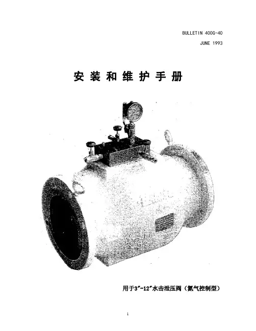
BULLETIN 400G-40JUNE 1993 安装和维护手册用于3"-12"水击泄压阀(氮气控制型)SECTION 1 安装和维护说明3"-12"水击泄压阀安装和启用1. 在安装水击阀以前,请确定阀门前的管道内没有脏东西、废弃物和金属屑,如果有条件,最好将阀门上游钢管进行吹扫,去除杂物。
2. 将阀门安装在管线上,确定阀门上游螺栓连接牢固。
(注意:为平抑温度变化产生的压力设定漂移,最好将扩大阀芯用的温差补偿氮气瓶埋地)。
3. 确定氮气供应系统的阀门是关闭的。
4. 连接氮气供应管线,从氮气供应系统阀门(H)到充气阀(D)。
5. 将阀门至于操作状态:5.1. 在开始使用水击泄放阀系统之前,应先打开连通温差平抑氮气瓶的截断阀(E),打开氮气充气阀(D)。
5.2. 缓慢打开氮气控制柜后的氮气瓶开关。
不要快速打开高压氮气瓶,避免高压氮气冲入系统损坏系统。
5.3. 缓慢调整氮气控制柜内的调压阀,顺时针为增加压力,直至调压阀下游(左侧)和水击阀上氮气压力表的压力达到标牌显示值,此时,水击阀和温差平抑氮气瓶都已经充压完成。
5.4. 缓慢打开水击阀后的截断闸阀(B)。
5.5. 缓慢打开水击阀前的截断闸阀(A)。
此时阀前压力应低于阀腔内压力,阀门保持关闭。
6. 水击阀停止使用:6.1. 缓慢关闭水击阀前的截断阀(A)。
6.2. 缓慢关闭水击阀后的截断阀(B)。
6.3. 通过水击阀前后管道上的排放阀将阀门前后管道内的压力泄出,如果没有排放阀的设计,则在拆除阀门时,应缓慢松开阀门与管道连接的螺栓,让压力从法兰连接处泄出。
关闭水击阀上的充气阀(D)和截断阀(E)。
缓慢打开水击阀上部的泄压阀(F),将阀腔内的压力泄出。
水击泄压阀的修理注:在阀门部件专有名称后,括号内的编号为阀门部件的编号,详见阀门的拆解图形的指示。
1. 确定阀门前后,及阀腔内压力已经泄出。
2. 如图二所示,将氮气控制系统取下;或将连接氮气控制系统的氮气管连接接头分开。
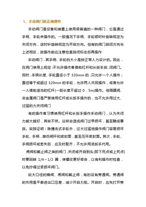
1、手动阀门的正确操作手动阀门是设备和装置上使用很普遍的一种阀门,它是通过手柄、手轮来操作的。
一般情况下手柄、手轮顺时针旋转规定为关闭方向,逆时针旋转规定为开启方向。
但有的阀门启闭方向与上述相反,故操作前应注意检查启闭标志后再操作手动阀门,其手柄、手轮的大小是按正常人力设计的。
因此,在阀门使用上规定:不允许操作者借助杠杆和长扳手启、闭阀门。
同时,手柄长度、手轮直径小于320mm的,只允许一个人操作;直径等于或超过320mm的手轮,允许两人共同操作,或者允许一人借助适当的杠杆(一般长度不超过0.5m)操作。
但隔膜阀、非金属阀门是严禁使用杠杆或长扳手操作的,也不允许用过大、过猛的力关闭阀门有的操作者习惯使用杠杆和长扳手操作手动阀门,认为关闭力越大越好,其实不然。
这样会造成阀门过早损坏,甚至酿成事故。
实践证明:除撞击式手轮外,过大过猛地操作阀门容易损坏手轮、手柄,擦伤阀杆和密封面,甚至压坏密封面。
其次,手轮、手柄损坏或丢失后,应及时配齐,不允许用活扳手代用。
闸阀和截止阀之类的阀门,关闭或开启到头(即下死点或上死点)时要回转1/4~1/2圈,使螺纹更好密合,以有利操作时检查,以免拧得过紧损坏阀门。
较大口径的蝶阀、闸阀和截止阀,有的设有旁通阀。
旁通阀的作用是平衡进出口压差,减少开启力矩。
开启时,应先打开旁通阀,然后再开启大阀门。
开启蒸汽阀门前必须先将管道预热,排出凝结水。
开启时要缓慢,以免产生水锤现象,损坏阀门和设备。
开闭球阀、蝶阀、旋塞阀时,当阀杆顶面的沟槽与通道平行时,表明阀门在全开启位置;当阀杆向左或向右旋转90。
时,沟槽与通道垂直时,表明阀门在全关闭位置。
有的球阀、蝶阀、旋塞阀以扳手与通道平行为开启,垂直为关闭。
三通、四通阀门的操作应按开启、关闭、换向的标记进行,操作完毕后应取下活动手柄。
对有标尺的闸阀和节流阀,应检查调整好全开或全闭的指示位置。
明杆闸阀、截止阀也应记住它们全开和全闭的位置,这样可以避免全开时顶撞死点。
安装、操作与维护说明书大型摆阀带双作用气动驱动器168系列公称直径DN 400 – 500 mm (内径 16" – 20")本产品手册适用于以下产品订购编号:168..-….-….样品图603171CA 2018-09-19版168系列2/29 2018-09-19版 603171CA版本说明制造商: VAT Vakuumventile AG, CH-9469 Haag, Switzerland官网:电话:传真: 电子邮件: +41 81 771 61 61 +41 81 771 48 30 ***************发行方 VAT Vakuumventile AG, CH-9469 Haag, Switzerland编辑 VAT Vakuumventile AG, CH-9469 Haag, Switzerland印制 VAT Vakuumventile AG, CH-9469 Haag, Switzerland版权 © VAT Vakuumventile AG 2018未经VAT 书面许可,严禁以复印、缩微胶片等途径或利用任何其它复制工艺复制本说明书的任何部分,或通过电子系统处理、复制或分发本说明书的任何部分。
违者将赔付损害赔偿金。
VAT 原装固件以及更新后的最新款VAT 固件适用于VAT 产品。
VAT 固件含范围有限但无期限限制的用户使用许可。
除预期用途外或经许可复制VAT 固件,不得以任何其它形式复制VAT 固件或将之用于任何其它用途。
特别是,严禁将VAT 固件的复制品提供给他人。
尽管本说明书中使用了各种商品名称、品牌名称和商标等信息,但第三方不得认为这些名称不受保护且无权随意使用这些名称。
此规定符合相关品牌名称与商标法及法案的规定。
168系列目录1产品描述 (5)1.1产品标识 (5)1.2产品用途 (5)1.3相关文件 (5)1.4重要注意事项 (5)1.5技术数据 (5)2安全性 (6)2.1必读资料 (6)2.2危险等级 (6)2.3人员资质 (7)2.4安全标签 (7)3设计与功能 (8)3.1设计 (8)3.2功能 (8)4安装 (9)4.1开箱 (9)4.2将阀门装入系统 (9)4.2.1允许力度与弯矩 (11)4.3压缩空气连接 (12)4.4电气连接 (12)5操作 (13)5.1正常操作 (13)5.2升温状态下操作 (13)5.3压缩空气发生压降时的阀门特性 (13)5.4断电时的阀门特性 (13)5.4.1应急手动操作 (13)5.5三位置驱动器 (选配件) (15)5.5.1三位置驱动器的控制逻辑 (15)5.5.2调整第三位置 (15)5.6故障排除 (16)6维护 (17)6.1维护间隔时间 (17)6.2所需工具 (18)6.3更换阀板/机构单元 (18)7维修 (21)8拆装与储存 (22)8.1拆装 (23)8.2储存 (23)603171CA 2018-09-19版3/29168系列9包装与运输 (24)9.1包装 (25)9.2运输 (25)10处理 (26)11备品备件 (27)12附录 (28)12.1组装图 (28)12.2阀板机构组装图 (29)4/292018-09-19版603171CA168系列 产品描述603171CA 2018-09-19版5/291产品描述1.1产品标识制造号和订单号直接印在产品上或标示牌上。
止回阀安装操作手册前言止回阀的设计和制造是按照使用寿命长、无故障应用的要求进行并提供给客户的。
本手册给客户提供所有相关阀门安装、操作和长期使用维护的信息,所提供的图纸均为标准结构的图纸。
一、安装前的注意事项1.阀门到达现场后,应仔细检查是否在运输途中受损。
2.在没有完成安装前,应保留阀门的包装和保护的设施。
3.如果阀门的通道以及法兰端面等与管路安装有关的地方被裸露,应采取措施加以保护,以防止杂质进入阀门体腔。
4.阀门安装前,应检查和清洗管道,防止杂质如砂子、电焊渣等损坏阀瓣和阀体密封面。
5.如果阀门在安装使用前需要存放较长时间,应在阀门裸露表面涂上防锈油,并建议将阀门处于全关位置时存放在干燥和通风的地方,通道两端应上好闷盖保护。
长时间存放后安装使用该阀门,应先进行清洗,并重新试压,合格后投入安装使用。
二、安装过程中的操作规程1.阀门不应负载管道的重量。
对管道的支撑将因管道系统的震动造成阀门的变形,阀门可以通过在阀体上安装管道夹和支撑物进行支撑,不应在法兰上固定支撑物(如图9)。
2.不要通过法兰螺栓的调整来纠正管道的不平行。
3.不允许用阀门承载管道的重量来避免管线的扭曲和阻塞。
4.合格的管道焊工必须按照ASME锅炉和压力容器标准第Ⅸ卷的规定进行焊接操作和评定。
5.止回阀安装时,首先要确定管道介质的流向与阀门允许的流向一致;安装螺纹端、对焊端、承插焊端、对夹式及法兰端连接阀门时,必须按照下列不同的程序和方法进行安装,以使阀门达到最佳的性能。
5.1螺纹端阀门的安装5.1.1安装前,应清洗阀门两端螺纹及其附件;5.1.2如必要,密封剂只能使用于管道或外螺纹上;5.1.3应使用带有正确尺寸的平板钳夹的扳手来安装六角或八角端;5.1.4不能选择较小尺寸的螺纹来安装管线阀门。
5.2对焊端阀门的安装5.2.1连接部位应保持同轴,连接端保留2~3mm间隙;5.2.2焊接处应使用内焊接垫环;5.2.3完成焊接后,应冲洗或清刮管道和阀门,以清除焊渣;5.2.4不允许快焊导致焊接材料过剩;5.2.5焊接时应采取适当的措施以避免阀座区域温度过高,使阀座及其密封面损坏;5.2.6如对焊端阀门购买时没有带延长的焊接接头,在焊接前,应拆除中间已经装配好阀瓣和阀座的阀体,并在原位置上安装上相同尺寸的隔离物后进行焊接;5.2.7当管道系统冷却至环境温度时将隔离物拆下,并重新安装阀体。
铸钢闸阀操作和维护手册1.总则该系统的阀门,在管线系统中用于关闭或开启管线,保持系统正常运行。
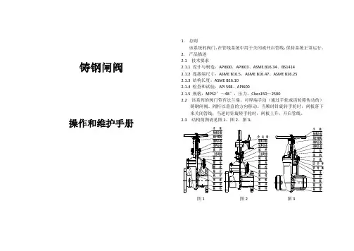
2.产品描述2.1 技术要求2.1.1 设计与制造:API600、API603、ASME B16.34、BS14142.1.2 连接端尺寸:ASME B16.5、ASME B16.47、ASME B16.252.1.3 结构长度:ASME B16.102.1.4 检查和试验:API 598、API6002.1.5 规格:MPS2″~48″,压力:Class150~25002.2 该系列的阀门带有法兰端、对焊端手动(通过手轮或齿轮箱传动的)铸钢闸阀。
阀杆以垂直的方向移动。
当顺时针旋转手轮时,闸板落下来关闭管线;当逆时针旋转手轮时,闸板上升,开启管线。
2.3 结构简图请见图1、图2、图3;图1 图2 图32.4 主要部件的名称和材料在表格1中(表1)3.存贮、维护、安装和操作3.1 存贮、维护3.1.1 阀门应被存贮在室内于干燥和通风处。
通道的端口应用盖子塞住。
3.1.2 长期存贮的阀门应进行定期检查和清理,特别是清理阀座密封表面,防止被损坏。
并且在机加工表面涂上防锈油。
3.1.3 如果存贮的时间超过18个月,阀门在安装使用前应进行测试,并做好记录。
3.1.4 安装后的阀门应定期进行检查和修理。
主要的维护点包括如下:1)密封表面2)阀杆和阀杆螺母3)填料4)阀体和阀盖的内部表面的污垢3.2 安装3.2.1 安装前重新确认阀门标识(如型号、公称通径、公称压力、材料)是依据管线系统的要求标识。
3.2.2 安装前仔细地检查阀门的通道和密封表面。
如有任何的赃物,应清理干净。
3.2.3 安装前,确保所有的螺栓已拧紧。
3.2.4 安装前,确保填料被压紧。
但不应妨碍阀杆的移动。
3.2.5 安装阀门的地方应是方便于检测和操作的,最好的位置应和管线是水平的,并且手轮在上,阀杆是垂直的。
3.2.6 对于正常的关闭阀门,阀门不适合安装在工作压力非常大的地方,以避免阀杆被损坏。
GR10、DR10单罐固定床软化阀安 装、使 用、维护手册(GR10单罐软化阀)西安市洁源环保水处理技术有限公司、一、控制原理(参见产品样本)Ⅰ 液晶显示控制器前面板各种操作显示说明流量模式“”显示界面当前工位:再生S:0200:设定再生用水量,由进水流量计计量,通过射流器的水量相当于8—10%浓度的盐水;D:0200:递减状态,到零切换;00.00t/h ;当前每小时进水量00000.0t :阀体长期累计通水量当前工位:清洗S:0200:设定清洗用水量,由进水流量计计量D:0200:递减状态,到零切换到软化; 00.00t/h ;当前每小时进水量 00000.0t :阀体长期累计进水量当前工位:软化S:0200.0:设定周期软化水量,由进水流量计计量D:0200.0:递减状态,到零切换到再生;00.00t/h ;当前每小时进水量00000.0t :阀体长期累计进水量操作按扭::手动转位;:参数设定;:移位;:加1A ”和“”已开。
B 、闭锁:设备无任何操作3分钟后,自动闭锁。
C 、模式切换:开锁状态下,操作按扭在时间模式“”D、 手动转位:开锁状态下,按此按钮多路阀切换到下一工位。
E、 参数设定:开锁状态下,按此按钮屏幕出现参数设定界面,确认和退出:数字移位G、:数字加1时间模式“ ”显示界面当前工位:再生当前工位:清洗当前工位:软化时间模式“ ”参数设定二、输入输出控制说明1、互锁线的连接如下图所示图1:互锁线路2.外部控制接口该阀可以通过外部其他控制系统控制进入、或RUN状态,外部控制系统给出的电压信号等同于按了一下手动转位()按钮。
图2:外接控制线路3.继电器输出接口⑴.继电器的接点容量为5A/250V。
⑵.继电器输出端口中,NO为常开端,COM为公共端,NC 为常闭端。
⑶.在连接继电器输出时,AC220V电源输入端需接漏电断路器。
不同模式下,继电器输出NO与COM,接通为“C”,断开为“×”, 有条件断开为“C×”模式 再生 清洗 运行 转位0 C C C×1 C C××2 ××C×3 C C× C×4 C C C××模式 应用场合0 进水电磁(动)阀模式:设备进水阀,转位泄压,关闭控制阀时关进水。
DR软化阀安装使用维护手则一、安装:1.选择合适位置:软化阀应该安装在水流进入建筑物的地方,离水表不远处。
保证软化阀可以方便地接触到水源,避免出现管道过长或过弯弯曲。
2.水平安装:软化阀应该水平安装,确保安装的平稳牢固。
安装时应使用垫片和螺丝固定软化阀,保证其不会晃动或倾斜。
3.连接管线:根据软化阀的进水口和出水口连接管线,使用合适的管道和接头,确保连接紧密可靠,避免漏水。
4.排放废水:软化阀在软化过程中会产生废水,应该将废水排放至污水管道或下水道,不能直接排放到环境中。
5.检查安装:安装完成后,应该检查软化阀的连接是否牢固,管道是否正常通畅,软化阀是否工作正常。
二、使用:1.开启软化阀:启动软化阀前,应该确保软化剂储罐中有足够的盐药。
按照软化阀说明书上的操作步骤,开启软化阀并调节工作参数。
2.监控软化效果:定期检查软化阀的软化效果,观察水质是否变软,若软化效果不佳,应该及时调整软化阀的参数或添加盐药。
3.添加盐药:软化阀内的软化剂需要定期添加盐药,保持软化效果。
根据软化阀的使用频率和水质硬度,合理添加盐药。
4.定期维护:定期清洁软化阀和软化剂储罐,确保软化阀的正常运行。
定期检查软化阀的各个部件,如阀门、管道等,发现问题及时修复或更换。
5.保持稳定使用环境:软化阀应该安装在通风干燥的环境中,避免长时间暴露在阳光下或潮湿环境中,以延长软化阀的使用寿命。
三、维护:1.定期清洁:软化阀内部可能会积聚碳酸钙等物质,影响软化效果,应该定期清洁软化阀的内部,保持通畅。
2.更换软化剂:软化阀的软化剂有一定的寿命,过期或用尽时应该及时更换,避免影响软化效果。
3.检查阀门和管道:定期检查软化阀的阀门和管道,确保其正常运行,避免漏水或故障。
4.保养软化阀:软化阀的密封圈、阀体等易受损部件需要定期保养,润滑以延长其使用寿命。
5.定期维护:定期请专业维修人员对软化阀进行维护和保养,确保软化阀的正常运行和延长使用寿命。
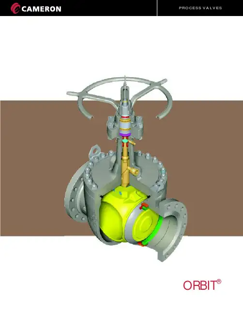
®ORBIT安装与维护手册CT-ORB-INS&MAIN/603/07 SF-3M®ORBIT安装与维护介绍正确的安装和恰当维护使阀门达到最佳的使用性能和延长使用寿命是非常重要的。
ORBIT 阀门和执行器在设计理念上就要求最小的维修量达到最佳的使用性能和最长的寿命。
对与ORBIT来说,润滑只是减少移动部件的摩擦而不是密封的需要,正确的润滑及密封步骤应根据阀门的应用工况及操作步骤而定。
ORBIT 推荐采用最低限的润滑及密封。
对于配备了可注入盘根的注入口的ORBIT阀门,注入盘根的功能只能在阀杆泄漏时才使用。
如需更多Orbit阀门和执行器的信息,请向当地Orbit阀门业务代表咨询。
CT-ORB-INS&MAIN/603/07 SF-3M1®ORBIT23 & 45, 6 & 7889 & 1010111212, 13 & 1415 & 16171819安装与维护安装前的检测手动操作阀门的安装带执行器阀门的安装参考数据型号的数字和代码解释阀门开关位置指示参考数据表终端法兰及螺栓的尺寸榫槽面法兰的槽道号参考表阀门润滑点的示例图润滑润滑步骤和推荐的润滑剂阀门和执行器的润滑阀杆盘根填料的调整阀杆盘根填料的调整阀杆盘根的材料商标信息商务条款工厂及产品其它 Orbit 阀门信息技术参考资料阀门与执行器尺寸自动化阀门阀门自动控制单元部件列表及订购介绍目 录SIZECLASS212345678®ORBITCT-ORB-INS&MAIN/603/07 SF-3M安装前的检查首先检查阀门铭牌上标示的尺寸,压力等级和阀型(Trim)等数据。
阀体上同时标注有该阀门的尺寸和压力等级。
根据铭牌上的数据以及位号,确认该阀门适用于即将安装的位置和使用工况。
检查手轮和阀位指示杆是否完好。
如果是法兰连接的阀门,应该拆除法兰保护盖,并检查法兰表面是否有损伤。
给水泵最小流量调节阀安装和维护手册沈阳方政阀门有限公司目录1.应用范围 (1)2.作用原理 (1)3.性能优点 (1)4.技术简介 (1)4.1选材和加工 (1)4.2多级节流 (1)4.3过封度 (1)4.4分开节流面与密封面 (1)4.5线密封型式 (1)4.6控制同心度 (2)4.7密封自力加压 (2)4.8浮动连接 (2)4.9防卡硬度差 (2)4.10合理间隙 (2)5.工作原理 (2)6.材料 (2)7.注意事项 (3)7.1吊环螺栓起吊范围 (3)7.2安装 (3)7.3使用 (4)7.4检查 (4)9.拆卸和装配 (5)10.阀门型号编制说明 (6)11.气动阀门结构 (7)12.气动阀门解体与组装 (8)13.气动执行器调校 (9)14.气动带定位器调节阀现场调试的方法 (9)15.气动调节阀常见故常及排除 (11)16电动阀门结构 (12)17.电动阀门解体与组装 (13)18.电动调节阀常见故常及排除 (14)1.应用范围我公司从国外引进先进技术同时,参加了很多新型能源电力设备,石油炼化、化工、精细化工领域的技术改革。
在这样的发展环境下,主要生产设备中给水泵系统和主要辅助设备。
我公司生产研发给水泵整套系统设备。
针对现场发生问题和使用情况研发新一代最小流量调节阀,最小流量调节阀主要应用在压差较大的工作环境。
最小流量调节阀适用于电力设备,石油炼化、化工、精细化工等领域。
2.作用原理当给水泵低于最小流量运行时,通过最小流量阀把水回流到除氧器中,在经过给水泵在循环增加给水泵的入口给水流量,保证给水泵安全运行。
当给水泵流量大于最小流量并有一定余量时,关闭在循环阀,以提高经济性。
最小流量调节阀主要功能有调节介质流量大小,减压作用,溢流作用。
3.性能优点△通过控制阀门行程来调节介质通过阀芯流量大小;△通过多级涡流和笼罩降低给水泵出口压力降至除氧器压力,保护给水泵过热以及产生气蚀,防止除氧器超压;△给水泵出口管道流量过高时,最小流量调节阀还可以把多余流量回流除氧器,节约资源,提高效能;4.技术简介4.1选材和加工阀内组件选材加工及热处理工艺独特,保证了阀内组件性能稳定、硬度高等特点,这一性能和硬度指标远超同类产品。
1 Contents1 Contents (1)2 Introduction (2)3 Design (2)4 Operation (2)4.1 Double Acting (DA) (2)4.1.1 CCW Movement (2)4.1.2 CW Movement (2)4.2 Spring Return (SR) (3)4.2.1 CCW Movement (3)4.2.2 CW Movement (3)4.3 Spring Return (SO) (3)4.3.1 CW Movement (3)4.3.2 CCW Movement (3)5 Installation (4)5.1 Installation on Valves (4)5.2 Air Supply (4)5.3 Lubrication (4)5.4 Travel Adjustment (4)6 Disassembly Procedures (5)6.1 Removing End Caps (5)6.1.1 DA & DR Models (5)6.1.2 SR & SO Models (5)6.2 Removing Piston(s) (5)6.3 Removing the Pinion (6)7 Changing Configurations (6)7.1 3R2500 Fail CW to Fail CCW (DA to DR, SR to SO) (6)7.2 3R3500 Fail CW to Fail CCW (DA to DR, SR to SO) (7)8 Assembly Procedure (7)8.1 Assembling Pinion (7)8.2 Assembling Piston(s) (7)8.3 Assembling End Caps (7)8.4 Setting Stop Bolts (8)9 Spare Parts (9)10 Bill of Materials (9)2 IntroductionThe following Installation and Operation Manual is a living document and will continuously be updated as the implementation of the 3R Scotch Yoke Actuators occurs. If you have any questions on the 3R Scotch Yoke Actuators, please contact A‐T Controls.NOTES:∙This manual is also applicable to the Series 2R 2500 and 3500 Scotch Yoke Actuators.∙For the sake of this document, the Drive Shaft may be referred to as the Pinion. Any instances of these two terms are referring to the Drive Shaft (3) in Bill of Materials.∙Throughout this document numbers may be seen in parentheses after a component. These numbers correspond to the numbers in the Bill of Materials that can be found toward the end of the document.3 DesignTriac 3R2500 & 3R3500 Scotch Yoke Actuators are designed and engineered to provide high cycle-life to meet the demands needed. They are offered in both double acting and spring return configurations that feature:∙Dual Travel Stops for open and close adjustment of 0±5° to 90±5°∙Multiple Temperature optionso Standard working temperature (‐5°F to 175°F)o Low temperature ( ‐45°F to 175°F)o High temperature (0°F to 300°F)∙Maximum working pressure 150 psi∙Air Supply Pressure of 40 ‐ 150 psi∙Operating media ‐ clean dry air, nitrogen, non‐corrosive gas or light hydraulic oil.∙NAMUR ‐ VDI/VDE 3845 accessory mounting∙ISO 5211 Valve mounting 4 Operation4.1Double Acting (DA)4.1.1CCW MovementApplying air pressure to Port 1 pressurizes the inside chamber and drives the piston(s) of the actuator outward. This action results in the counterclockwise rotation of the drive shaft. As the piston(s) are driven outward, air is exhausted from the outside chamber(s) through Port 2.4.1.2CW MovementApplyingairpressure to Port 2 pressurizes the outside chamber(s) and drives the piston(s) of the actuator inward. This action results in the clockwise rotation of the drive shaft. As the piston(s) are driven inward, air is exhausted from the inside chamber through Port 1.4.2 Spring Return (SR)4.2.1 CCW MovementApplying air pressure to Port 1 pressurizes the inside chamber and drives the piston(s) of the actuator outward. This action results in the counterclockwise rotation of the drive shaft. As the piston(s) are driven outward, the spring(s) are compressed, storing energy, and air is exhausted from the outside chamber(s) through Port 2. 4.2.2 CW Movement∙ With no air assist : Exhausting air from the inside chamber through Port 1 allows the stored energy in the compressed spring(s) to force the piston(s)inward. This action results in the clockwise rotation of the drive shaft.∙ With air assist : Applying air pressure to the outside chamber(s) through Port 2 forces the piston(s)inward. This action results in the clockwise rotation of the drive shaft. As the piston(s) are driven inward, from the stored energy in the compressed spring(s) and air pressure, air is exhausted from the inside chamber through Port 1.4.3 Spring Return (SO)4.3.1 CW MovementApplying air pressure to Port 1 drives the piston(s) outward, which compresses the spring(s) and turns the drive shaft clockwise as the air volume on the outside of the piston(s) exhausts through Port 2. 4.3.2 CCW Movement∙ With no air assist: Exhausting air from the inside chamber through Port 1 allows the stored energy in the compressed spring(s) to force the piston(s) inward. This action results in the counterclockwise rotation of thedriveshaft.∙ With air assist: Applying air pressure to the outside chamber(s) through Port 2 forces the piston(s) inward. This action results in the counterclockwise rotation of the drive shaft. As the piston(s) are driven inward, from the stored energy in the compressedspring(s) and air pressure, air is exhausted from the inside chamber through Port 1.5 Installation 5.1 Installation on ValvesWARNING : FOR YOUR SAFETY, IT IS IMPORTANT THAT THE FOLLOWING PRECAUTIONS BE TAKEN BEFORE ANYDISASSEMBLY OF THE ACTUATOR OCCURS.▪ Depressurize the lines and cylinder of the actuatorbefore removing any components.▪ On spring return actuators, be careful to loosen theend cap bolts evenly due to the preload on the springs.Triac actuators are mounted directly to valves or adapted to the valve by means of an intermediate bracket and coupler. The coupler adapts the output of the actuator to the valve shaft. Pipelines can behorizontal, vertical, or other positions. When mounting the actuator to a valve using a mounting kit; the drive shaft, coupling device and valve stem should becentered and concentric to prevent any side loading to the bottom pinion radial bearing and valve stem seal area. After mounting, it may be necessary to adjust the end of travel stop for proper open or closed valve position. Pneumatically stroke the actuator several times to assure proper operation with no binding of the coupler.5.2 Air SupplyPneumatic piping to the actuator and associated accessories should follow the best practices for instrument pneumatic piping systems:∙ Line shall be free of water, oil, pipe sealant or other contaminants.∙ Operating medium is to be filtered dry air or inert gaswhich is filtered to 50‐micron particles size or less.∙ Actuator shall be supplied with proper air pressure and air volume. ∙ Triac 3R Scotch Yoke Actuators shall not exceed a maximum working pressure of 150 psi. ∙ Spring Return Models:Note: If exhaust port is not piped, it is important that the exhaust port is not exposed to a corrosive atmosphere.Please contact A ‐T Controls for possible solutions if non ‐typical conditions exist.5.3 LubricationTriac 3R Scotch Yoke Actuators are lubricated from the factory and no additional lubrication is required unless the actuator will be performing more than 100,000 cycles.∙ If more than 100,000 cycles will be performed, an oil mist lubricator is recommended.[1] [2]o Use oil type VG32 Class in temperature range from 15 to 158°Fo Set oil mist lubricator to lowest setting. [1]: If a Triac Scotch Yoke Actuator has been in operation with oil mist lubrication, it cannot be discontinued. [2]: If the actuator is equipped with a pneumatic positioner or controller, oil mist lubricated air shall not be used unless the instrument manufacturer indicates that used instrument is compatible with lubricated air.5.4 Travel AdjustmentWARNING : TO AVOID CATASTROPHIC FAILURE TO ACTUATOR,AIR MUST BE REMOVED FROM ACTUATOR BEFORE ANY TRAVEL ADJUSTMENTS ARE MADE.The Triac 3R Scotch Yoke Actuators have travel stopadjustments in both the clockwise andcounterclockwise directions. A 5° overtravel featureprovides adjustments from ‐5° to +5° at the 0° clockwiseposition, and from 85° to 95° at the 90° counterclockwise position.All actuated valves require accurate travel stop adjustments at both ends of the stroke to obtain optimum performance and valve seat life. Theaccumulation of tolerances in the adaption of actuators to valves is such that there must be a range ofadjustment for both ends of the stroke to achieve the expected performance. See the valve manufacturer’s IOM on how the travel should be adjusted. The following are typical features seen:∙ Ball & Plug Valves: require precise adjustment at the open and closed position. This is to protect the seat from the flow media and to assure absolute shut ‐off in the closed position.∙ Butterfly Valves: require precise adjustment at the open and closed position. This is to assure full shut ‐off, to prevent disc overtravel which can damage the seat in the closed position, and to assure maximum flow in the open position.∙ Tee Assemblies: where two valves are operated in tandem through a single operator, (3‐wayconfiguration) require precise adjustment at both ends of the stroke. This is to assure the seating of both valves.6 Disassembly ProceduresWARNING : FOR YOUR SAFETY, IT ISIMPORTANT THAT THE FOLLOWING PRECAUTIONS BE TAKEN BEFORE ANY DISASSEMBLY OF THE ACTUATOR OCCURS.▪ Depressurize the lines and cylinder of the actuatorbefore removing any components.▪ On spring return actuators, be careful to loosen the endcap bolts evenly due to the preload on the springs. ▪ Disconnect electrical supplies6.1 Removing End Caps6.1.1 DA & DR Models1. Loosen both the Clockwise (Right) andCounterclockwise (Left) Travel Stop Bolt Nuts (12). 2. Back out Travel Stops Bolts (11) about six turns sothe Travel Stop Cam (7) does not interfere with the Travel Stop Bolts.3. Using a 14mm hex key wrench remove the 4 End CapBolts (23) from each side.4. Remove End Caps (22) away from the Actuator Body(33). 6.1.2 SR & SO Models1. Loosen both the Clockwise (Right) andCounterclockwise (Left) Travel Stop Bolt Nuts (12). 2. Back out Travel Stop Bolts (11) about six turns so theTravel Stop Cam (7) does not interfere with the Travel Stop Bolts.3. Using a 14mm hex key wrench remove the 4 End CapBolts (23) from each side.4. Remove End Caps (22) away from the Actuator Body(33).CAUTION! Make sure to remove end cap bolts evenly as there is preload from the spring.WARNING! Do NOT touch the Pre ‐Tensioning Bolt (29) or the Pre ‐Tensioning Nut (25). The SpringAssemblyis preset from the factory. Any adjustments could result in injury or death.6.2 Removing Piston(s)NOTE : Make sure to designate or mark the positions of the piston(s) and pinion during disassembly. The piston and yoke positions will change relative to their original positions.1.If End Caps (22) are not removed, see Removing EndCaps Section for procedure to remove the End Caps before continuing.2.Rotate the Pinion (3) until the Piston(s) (16) are atthe end of the Actuator Body (33). This can be done by turning the Pinion (3) with a wrench on the flats located at the top of the pinion.3.Remove the Piston(s) (16) from the cylinder.6.3Removing the Pinion1.If End Caps (22) and Piston(s) (16) are not removed,see Removing End Caps Section and RemovingPiston(s) for procedures to remove the End Capsand Piston(s) before continuing.2.Set the Actuator Body on an end.3.Rotate the Pinion (3) until the flat side of the YokePin (6) is facing upward.NOTE: There are two different sides to the Yoke Pin (6). A flat smother side and a side that is peened.ing a punch rod on the flat side of the Yoke Pin (6),knock out the Yoke Pin.CAUTION: Do not damage the Yoke (5).5.Remove Drive Shaft Snap Ring (35), Support Washer(36) and Support Bushing (37) located at top of thePinion (3).6.Tap the top of the Pinion (3) lightly with a plasticmallet to remove the Pinion from the upper andlower drive shaft bushings (2, 9).WARNING: When removing the Pinion (3),the Travel Stop Cam (7) and Yoke (5) must beguided off the Pinion and removed from theActuator Body (33) cylinder while removingthe Pinion.7 Changing Configurations7.13R2500 Fail CW to Fail CCW (DA to DR,SR to SO)NOTE: Make sure to designate or mark thepositions of the piston(s) and pinion duringdisassembly. The piston and yoke positionswill change relative to their originalpositions.1.If End Caps (22) and Piston(s) (16) are not removed,see Removing End Caps Section and RemovingPiston(s) for procedures to remove the End Capsand Piston(s) before continuing.2.Set Actuator Body (33) on its end so the short side ofthe body is facing upward.3.Rotate the Pinion (3) until the flat side of the YokePin (6) is facing upward.NOTE: There are two different sides to theYoke Pin (6). A flat smother side and a sidethat is peened.ing a punch rod on the flat side of the Yoke Pin (6),knock out the Yoke Pin and remove from ActuatorBody (33) cylinder.CAUTION: Do not damage the Yoke (5).5.Without rotating the Pinion (3), rotate the Yoke (5)180°.6.Replace the Yoke Pin (6) by putting the flat side infirst and hitting the pin onthepeenedside.7.Grease cylinder surface with multi‐purpose grease.8.Rotate the Piston (16) 180° from original position sothat the Piston Roller (32) is properly seated in the Yoke (5).9.Rotate the Pinion (3) 90° counterclockwise toconfirm proper alignment.10. See Assembling End Cap Section and Setting StopBolts Section to complete configuration change.7.23R3500 Fail CW to Fail CCW (DA to DR,SR to SO)NOTE: Make sure to designate or mark the positions of the piston(s) and pinion during disassembly. The piston and yoke positions will change relative to their original positions.1.If End Caps (22) and Piston(s) (16) are not removed,see Removing End Caps Section and RemovingPiston(s) for procedures to remove the End Capsand Piston(s) before continuing.2.Grease Actuator Body (33) cylinder surface withmulti‐purpose grease.3.With the Pinion (3) in the counterclockwise positionwhen the Piston(s) (16) were removed, rotate thePiston(s) 180° from original position.4.Push the Piston(s) (16) into the Actuator Body (33)making sure the Piston(s) Roller Bearings (32) areproperly seated in the Yoke (5).5.Rotate the Pinion (3) 90° counterclockwise toconfirm proper alignment.6.See Assembling End Cap Section and Setting StopBolt Section to complete configuration change.8 Assembly Procedure8.1Assembling Pinion1.Inspect all parts for wear and replace any worn partsas needed. Make sure all parts are greased withmulti‐purpose grease.2.If rebuilding, on the Pinion (3) replace:a.Drive Shaft Lower O‐ring (1)b.Drive Shaft Lower Bushing (2)c.Drive Shaft Upper Bushing (9)d.Drive Shaft Upper O‐ring (10)3.Install the Drive Shaft Middle Bushing (4) that goesbelow the Yoke (5) onto the Pinion (3).4.With the Yoke (5) being supported in the ActuatorBody (33) cylinder, insert the Pinion (3) through thebottom Actuator Body cylinder opening, Yoke (5),Drive Shaft Middle Bushing (4) that goes above the Yoke, Travel Stop Cam (7) and then throughActuator Body (33) cylinder top opening.NOTE: Make sure that the Travel Stop Cam(7) is oriented for correct configuration.5.Install the existing, or if rebuilding new, SupportBushing (37), Support Washer (36) and Drive ShaftSnap Ring (35).6.Verify the orientation of the Yoke (5) and align theYoke Pin (6) hole on the Yoke with correspondinghole on the Pinion (3).7.Relace the Yoke Pin (6) by putting the flat side in firstand hitting the Yoke Pin on the peened side.8.2Assembling Piston(s)1.Inspect all parts for wear and replace any worn partsas needed. Make sure all parts are greased withmulti‐purpose grease.2.If rebuilding, on the Piston(s) (16) replace:a.Piston O‐Ring (17)b.Piston Guide Ring (18)3.Verify the orientation of the Piston(s) (16) as neededfor designed operation.4.Push the Piston(s) (16) into the Actuator Body (33)cylinder making sure the Piston(s) Roller Bearing(s)(32) are properly seated in the Yoke (5).5.Rotate the Pinion (3) 90° counterclockwise toconfirm proper alignment.8.3Assembling End Caps1.Inspect all parts for wear and replace any worn partsas needed.2.Install the existing End Cap O‐ring (27) or replace theEnd Cap O‐ring if rebuilding.3.Verify the Pinion (3) is rotated so that Piston(s) areas far into the Actuator Body (33) cylinder aspossible.4.Install the Spring Assembly End Cap (22) or End Caponto the cylinder body.∙Spring Return: Thread the 4 End Cap Bolts (23)down evenly, moving between the bolts, until the End Cap (22) and Actuator Body (33) contact.Repeat for opposite End Cap.∙Double Acting: Thread the 4 End Cap Bolts (23)until the End Cap (22) and Actuator Body (33)contact. Repeat for opposite End Cap.5. Tighten End Cap Bolts (23) to 1,440 in‐lbs using a14mm hex key wrench.8.4Setting Stop Bolts1.If rebuilding, replace the Travel Stop O‐Ring (14) onthe Travel Stop Bolt (11).2.Rotate the actuator to the desired clockwiseposition. 3.Tighten the Clockwise (Right) Travel Stop Bolt (11)until contact with the Travel Stop Cam (7).4.While holding the Clockwise (Right) Travel Stop Bolt(11), tighten the Travel Stop Nut (12) until theTravel Stop Washer (13) contacts the Actuator Body(33); compressing the Travel Stop O‐ring (14).5.Rotate the Actuator to the desired counterclockwiseposition.6.Tighten the Counterclockwise (Left) Travel Stop Bolt(11) until contact with the Travel Stop Cam (7). 7.While holding the Counterclockwise (Left) TravelStop Bolt (11), tighten the Travel Stop Nut (12) until the Travel Stop Washer (13) contacts the ActuatorBody; compressing the Travel Stop O‐ring (14).9 Spare Parts10 Bill of MaterialsA‐T Controls product, when properly selected, is designed to perform its intended function safely during its useful life. However, the purchaser or user of A‐T Controls products should be aware that A‐T Controls products might be used in numerous applications under a wide variety of industrial service conditions. Although A‐T Controls can provide general guidelines, it cannot provide specific data and warnings for all possible applications. The purchaser / user must therefore assume the ultimate responsibility for the proper sizing and selection, installation, operation, and maintenance of A‐T Controls products. The user should read and understand the installation operation maintenance (IOM) instructions included with the product and train its employees and contractors in the safe use of A‐T Controls products in connection with the specific application.While the information and specifications contained in this literature are believed to be accurate, they are supplied for informative purposes only. Because A‐T Controls is continually improving and upgrading its product design, the specifications, dimensions and information contained in this literature are subject to change without notice. Should any question arise concerning these specifications, the purchaser/user should contact A‐T Controls.For product specifications go to http://a‐/Downloads/A‐T Controls, Inc. • 9955 International Boulevard, Cincinnati, OH 45246 • Phone: (513) 530‐5175 • Fax: (513) 247‐5462 • www.a‐。
阀门安装操作维护手册阀门的保管与安装质量直接影响着阀门的使用,为了进一步加强阀门在运输、装卸、保管、安装、操作和养护各个环节的控制,保证阀门的质量,项目部在结合各生产厂家安装、操作和维修手册的基础上,编制了本项目使用的阀门操作维护手册,施工安装单位认真学习,并对照手册的要求安装、操作和维护阀门。
保证项目正常运行。
线路截断阀和站场ESDV阀(驱动方式:气液联动连接形式:全焊接)1. 安装注意事项1.1阀门吊装拉运1.1.1 应采用正确的方式吊装阀门,使阀体支撑负荷。
警告:其它凸出部件上。
支耳和阀门端颈为系吊链的正确位置,请切勿将吊链系于手轮、齿轮箱或执行器1.1.2如果阀门上装配有吊耳, 则应用吊耳吊装阀门。
1.1.3在吊装阀门期间应使阀门端部保护盖保持在原位。
只有当阀门安装完毕后,才可移去保护盖。
1.1.4 吊装时应逐个阀门吊装,不得多个阀门同时吊装。
阀门在摆放时禁止叠加。
警告:在吊装时,请注意保护阀门端面及阀门配件不受损坏,否则将导致阀门受损。
1.1.5 阀门拉运前要对阀门进行逐个检查,对存在外观缺陷、手轮变形、部件损坏的情况,施工单位可以拒绝拉运。
1.1.6阀门拉运时要对每台阀逐个固定,防止阀门在运输过程中倾倒、相互摩擦和碰撞。
1.1.7 阀门在拉运时要采取防雨措施。
1.1.8 阀门运抵现场后要设专人负责保管。
存放的场地要求平整,下铺上盖,排列整齐,小阀门可以放在货架上。
存放时注意保护好阀门封盖和法兰密封面。
禁止在存放期间闲杂人员对阀门进行开关。
阀门位置:球阀可安装在任何位置,阀门的任何一端均可作为上游端。
图1-正确的利用端颈吊装方式图 2 –正确的利用吊耳的吊装方式1.2焊接说明:阀门焊接连管前,前后管道应同轴,断面应平行。
带有支架的阀门必须放置在加固的基础之上,使得球阀不承受来自管线的附加应力。
阀门安装前管线必须吹扫干净,清除掉管道内的油污、焊渣和杂物。
1.2.1在预热、焊接或热应力释放时,距焊缝3″(75mm)以外阀体上的任何点处温度均不能超过400°F(200°C)。
CAMERON T32电动球阀使用及维护保养手册1.手册内容本手册规定了延安分公司CAMERON T32阀门的工作原理、操作规程和定期维护保养规程。
2.应用范围本阀门应用于延安分公司安边压气站。
3.结构特点3.1 阀体(详见附件喀麦隆球阀安装和维护手册)3.1.1、结构3.1.2、作用:用于切断或接通管路中的介质;3.1.3、应用范围:气体介质或液体介质;3.1.4、优点:紧凑球型的阀体设计避免了阀体联接法兰(法兰焊接),因此减小阀门外形尺寸和根除泄漏渠道。
3.2 执行机构(详见附件电动执行机构)3.2.1、结构:由电机、电源模块、控制模块、力矩控制器、阀位控制器、电缆管道入口、端子和接线组成;3.2.2、作用:对控制对象施加控制作用;3.2.3、应用范围:工业自动化设备;3.2.4、优点:使用方便,便于集中控制,灵敏度和精度较高。
缺点:结构较复杂,容易发生故障。
4.操作规程4.1手动操作4.1.1、用红色旋钮锁定到“stop”位置,4.1.2、手动挂上离合器,4.1.3、确认离合器闭合后,转动手轮,实现开或关操作, 4.1.4、观察液晶显示面板上的阀门开度,根据开度,选择停止操作,(球阀只用于全开或全关操作)4.1.5、做好记录。
4.2电动现场控制操作4.2.1、将红色旋钮由“STOP”位置旋转到“就地控制”后固定。
4.2.2、轻轻的把黑色旋钮向开或关一侧即松手(不可用力过猛,旋转到15°-45°即可)4.2.3、操作完毕后将红色旋钮的箭头方向打倒“STOP”位置,4.2.4、做好记录。
4.3、远程控制操作4.3.1、将红色旋钮由“STOP”位置旋转到“远控控制”后固定,4.3.2、由远程控制(调度中心)执行电动球阀的开和关操作,4.3.3、做好记录5.维护保养5.1、日常维护保养5.1.1、检查阀体是否清洁,若有污物及时清理;5.1.2、检查各密封点有无跑、冒、滴、漏现象;5.1.3、检查阀门阀位指示是否正常;5.1.4、检查执行机构显示器是否正常(报警判断依据如下)5.2、周保养5.2.1、无5.3、月保养5.3.1、无5.4、季度保养5.4.1、对阀门进行盘活;5.5、春秋检保养5.5.1、注清洗液5.5.2、注密封脂5.5.3、清洗液/密封脂用量表6故障处理6.17常用配件及工具(仿宋,四号,加粗)7.1常用备件(仿宋,四号)7.2常用工具8生产厂家。
请将这些说明与所装阀门 放在一起,供日后参考扫描二维码可获取视频和更多技术文件I-769N.Deluge-CHI安装、维护和测试手册769N 系列 FireLock NXT ™ 雨淋阀气动(干式先导)释放、液动(湿式先导)释放和电动释放系统I-769N.Deluge-CHIREV_F769N 系列 FIRELOCK NXT™雨淋阀本节为系统投入运行和进行水流报警测试提供了快速参考。
在让系统投入运行之前,经验丰富、训练有素的安装人员应该阅读并理解本手册的全部内容以及所有警告消息。
776 系列低压执行机构的自动排气套管报警测试球阀排水阀自动排水套管球形滴阀柱塞控制阀系统主管排水阀所需的水流报警测试请参阅 NFPA 25、FM 数据表或任何适用的当地要求以执行水流量报警测试。
所在地区监管当局可能会要求更加频繁地进行这些检查。
请联系受影响地区的监管当局核实这些要求。
1. 请通知监管当局、远程报警站报警监控人员和水流报警测试时受影响地区的人员。
2. 将供水主管排水阀完全打开,冲洗掉供水中的所有污染物。
3. 关闭供水主管排水阀。
4. 打开报警测试球阀。
确认机械和电气报警器启动且远程监控报警站(如果配备的话)收到报警信号。
5. 核实所有报警器都工作正常后,关闭报警测试球阀。
6. 推入报警歧管组件上的球形滴阀柱塞,以核实报警管路中确实没有压力。
7. 核实所有报警器均已停止发声、报警管路已正确排空、远程报警站报警器已正确复位。
8. 确认报警歧管组件上的球形滴阀无漏水或漏气现象。
9.如果需要,将测试结果提供给监管当局。
气动(干式先导)释放配管已显示 (为清楚起见,未显示手动报警站)I-769N.Deluge-CHI / 769N 系列 FireLock NXT™雨淋阀 / 安装、维护和测试手册目录危险标识 (4)安装人员安全须知 (4)重要安装信息 (5)水压试验 (5)收货 (6)配管尺寸 (7)配管组件 – 分解图 - 气动(干式先导)释放配管 (8)配管组件 – 分解图 - 液动(湿式先导)释放配管 (9)配管组件 – 分解图 - 电动释放配管 (10)阀门内部组件 – 剖视图和分解图 (11)供气要求 (12)底座式或竖管安装空气压缩机 (12)气站供气或罐式安装空气压缩机 (12)空气监控压力开关和报警压力开关设置 (12)湿式先导管路图表..................................13-15第一部分初始系统设置 (17)第二部分重置系统 (21)第三部分每周外部检查 (23)每月外部检查 (23)第四部分要求的主管排水测试 (25)要求的水流报警测试 (26)要求的水位和低气压报警测试 (27)要求的部分运行触发测试 (28)要求的全面运行触发测试 (29)第五部分要求的内部检查 (31)第六部分拆卸和更换阀瓣密封 (33)拆卸和更换阀瓣组件 (34)安装盖板密封垫圈和盖板 (35)拆卸和更换隔膜 (36)清洁空气和注水歧管组件中的阀芯 . . . . . . . . . . . . . . . . . . . . . . . . 37更换 776 系列低压执行机构中的过滤器(干式先导释放系统)..37第七部分故障排除............................................39危险标识标示的各种危险级别解释如下。
MANUAL VALVE SERIES 10V10VRMMMV/MVESW10P/15P10SM/20SM30VM30VRMM60VM60VRMM100VM2Parker Autoclave Engineers Instrumentation Products Division Erie, PA USA | Cat. 02-0024MET able of C onTenTspage1.0 Installation ........................................................................................................... 2 2.0 Packing Adjustment .............................................................................................. 2 3.0 Packing or Stem Replacement ............................................................................. 2 4.0 Seat Replacement ............................................................................................... 4 5.0 Service .. (4)6.0 Installation Summary Chart (5)Section 1.0InstallationNo adjustments are necessary prior to installation. Refer to Parker Autoclave Engineers’ Valve, Fitting and Tubing Catalog (Installation Section) for proper tubing connection installation.Note: The minimum and maximum temperature limits of the connection style and materials listed in the Valve, Fitting and Tubing Catalog.Section 2.0Packing AdjustmentIf the valve packing starts to leak, follow the steps listed below to reseal the valve stem.Note: The minimum and maximum temperature limits of the ap-propriate packing listed in the Valve, Fitting and Tubing Catalog.1. Relieve all pressure from the valve and remove it from the system.2. Turn valve stem to full open position.3. Loosen the packing gland locking device.4. While holding the valve body secure, use a torque wrench to tighten the packing gland to the value shown on the attached Installation Summary Chart. If a torque wrenchis not available, tighten the packing gland approximately 1/16 turn.5. Pressurize the valve to the maximum operating pressure and check for leaks.6. If the packing still leaks, relieve all pressure in the valve and repeat steps 4 and 5. If the packing does not seal after several attempts, it needs replaced (refer to Section 3.0).7. Reinstall the packing gland locking device.Section 3.0Packing or Stem Replacement1. Relieve all pressure from the valve and remove it from the system.2. Turn valve stem to full open position.3. Remove the packing gland locking device.Model # Order # Serial # Mfg. DateDrawing #3Parker Autoclave Engineers Instrumentation Products Division Erie, PA USA | Cat. 02-0024ME4. While holding the valve body (or housing for HT and LT valves) secure, unthread and remove the packing gland. The packing will stay on stems that have a larger stem tip below the packing (see Fig. 3: SW8, 10/20SM9, 10/20SM12, 10/20SM16).Note: For HT and LT valves, the housing must be removed where the stem tip is larger than the body cone ring ID (SW6, SM12 and SM16 valves). Remove the housing locking device and unscrew the housing from the valve body.5. Autoclave Engineers manual valves have three different type of stems; one piece non-rotating (figure 2), two piece pinned non-rotating (figure 4) and rotating (figure 5). Follow steps 6-9 for one piece non-rotating stems, steps 10-11 for two piece pinned non-rotating stems andstep 12 for rotating stems.One piece non-rotating stem 6. For stems without a larger stem tip, remove the bottom washer, packing and packing washer in the body. Place the bottom washer, packing and packing washer in the body. If the stem does not require replacement, screw the packing gland back into the body and tighten the packing gland to the value in the Installation Sum- mary Chart.7. Remove the handle by loosening the set screw(s) located in the larger hole of t he handle (use a 5/32 hex wrench for the 3" long handle, a 3/16 hex wrench for the 4" and 10-1/4" long handle) and remove it from the stem sleeve. Unscrew the stem from the packing gland. Remove the two nuts and thrust washer from the top of the stem assembly. Remove the stem from the stem sleeve. Remove the bottom thrust washer from the stem. For SW8, 10SM9 and 20SM9 valves, remove the stem collar by unscrewing it clockwise. For stems with a larger stem tip, remove the packing washer and packingfrom the stem.8.Clean thrust washers and all surfaces which mate with thrust washers with a clean cloth. Apply non-hardening lubricant (Jet-Lube SS-301 or similar) lightly to both faces of the thrust washer and the sleeve threads.9. For stems with a larger stem tip, place the bottom washer, packing and packing washer on the stem (remove the bottom washer from from the old stem if the stem is being replaced). For SW8, 10SM9 and 20SM9 valves, place the stem collar on the stem by threading it counter-clockwise. Place first thrust washer on the stem and slide stem into stem sleeve. Place second thrust washer on the stem sleeve. Replace hex nut lightly against the upper thrust washer and thread the stem assembly fully into the packinggland. Screw the packing gland into the body and tightento the value in the Installation Summary Chart. Open the valve completely, then close it one turn to remove the play. Finger tighten the hex nut, then use a wrench to tighten it approximately 1/8 of a turn. Install the lock nut and finger tighten it in place. While holding the lock nut secure, loosen the hex nut from the top washer and tighten it against the lock nut approximately 1/16 of a turn. Replace the handle by lining the hex socket set screw up against the flat spot on the stem sleeve and tightenit in place (DO NOT OVERTIGHTEN). In order to have a nonrotating stem, a slight amount of free play must exist between the stem sleeve and shaft. The handle should have a 10 degree maximum free play for "backlash". If the free play is excessive, it will be necessary to remove the handle and loosen the lock nut and tighten the hex nut further against the thrust washer. Tighten the lock nut as indicated above and check for free play. When the desired "backlash" is achieved, replace the handle as described above. Re-install the locking device.Two piece pinned non-rotating stems10. For high and low temperature valves that have two piece non-rotating stems, remove the groove pin holdingLOCK NUT HEX NUTSECOND THRUST WASHERSTEM SLEEVEFIRST THRUST WASHERSTEMFigure 1: Two-Piece Non-rotating Stem Assembly (Exploded)4Parker Autoclave Engineers Instrumentation Products Division Erie, PA USA | Cat. 02-0024MEthe upper and lower stem together by driving it out with a rigid small diameter rod and pulling it out with a pair of pliers. Remove the packing washer and packing from the stem. If a new lower stem is required, remove the housing andcone ring from the old stem and place the cone ring and housing over the new lower stem. Place the bottom washer, packing and packing washer on the stem. Insert the lower stem into the upper stem so that the groove pin holes line up. Drive the groove pin into the hole until it is flush with the outside diameter of the upper stem.11. Lubricate stem sleeve threads with Jet-Lube SS-301 or similar lubricant. Thread the stem sleeve all the way into the packing gland or the insert so that the stem is in the full open position. While holding the housing in a vice, torque the packing gland to the value in the Installation Summary Chart and tighten the locknut. Apply silicone grease or similar lubricant to the sealing surfaces of the cone rings. Apply Jet-Lube SS-301 or similar lubricant to the threads. Screw the housing into the valve body and torque the housing to the value in the Installation Summary Chart. Replace the housing locking device.Rotating Stem 12. Remove the handle from the stem. Unthread the stem from the packing gland. Apply Jet-Lube SS-301 or similar lubricant to the threads of the new stem and thread the new stem all the way into the packing gland. Line the set screw on the stem up with the flat spot on the stem and tighten the set screw. With the bottom washer, packing and packing washer installed in the body, screw in the packing gland and torque it to the value in theInstallation Summary Chart. Reinstall the packing glandlocking device.Section 4.0Seat Replacement(see Fig. 3)1. Relieve all pressure from the valve and remove it from the system. Turn the valve stem to the full open position.2. While holding the body secure, unscrew the seat retainer.3. Remove old seat and replace if necessary.4. Apply silicone grease or similar lubricant to sealing surfaces of seat. Apply Jet-Lube SS-301 or similar lubricant to the seat retainer threads.5. Replace seat and seat retainer. Make certain that the seat stays flat against the valve body. Tighten seat retainer tothe torque specified in the Installation Summary Chart.ACKING REGULA TING STEM TIP MET AL-TO-METAL SEA TINGFigure 2: Typical Valve AssemblyFigure 3: Valve with Replacement Seat5Parker Autoclave Engineers Instrumentation Products Division Erie, PA USA | Cat. 02-0024MESection 5.0ServiceFor service contact the Parker Autoclave Engineers’ Representa-tive in your area or FAX Parker Autoclave Engineers’ Support Services at 1-814-860-5703. Notes:HT - (high temperature extended stuffing box option). LT - (cryogenic extended stuffing box option).1SS30 is a registered trademark of Jet-Lube, Inc.Section 6.0Installation Summary ChartPlease see Installation Summary Chart on pages 6 & 7.Figure 4: Extended Housing Valve Assembly with Two PiecePinned Non-Rotating Stem6Parker Autoclave Engineers Instrumentation Products Division Erie, PA USA | Cat. 02-0024MES e c t i o n 4.0I n s t a l l a t i o n S u m m a r y C h a r tF o r t h e d i s c o n t i n u e d 20S V a n d 20S C S e r i e s u s e S M v a l v e sN o t e s :** V a l v e s e r i e s a n d c o n n e c t i o n s i z e i n s i x t e e n t h ’s o f a n i n c h a r e i n d i c a t e d . + F i n g e r t i g h t , t h e n 3/4 t u r n w i t h w r e n c h (T F E o n l y ). 175 f t . - l b s . (238.9) N -m w i t h T G p a c k i n g . 120 f t .-l b s . (162.7) N -m w i t h G Y p a c k i n g . ++ F i n g e r t i g h t , t h e n 3/4 t u r n w i t h w r e n c h (T F E o n l y ). 325 f t . - l b s . (443.8) N -m w i t h T G p a c k i n g . 140 f t .-l b s . (189.8) N -m w i t h G Y p a c k i n g . ~ U n l e s s o t h e r w i s e n o t e d , t o r q u e v a l u e s a r e f o r T F E p a c k i n g . F o r T G p a c k i n g a d d 10% a n d f o r G Y p a c k i n g a d d 25% t o t h e s e v a l u e s . * T o r q u e w r e n c h n o t r e q u i r e d f o r A E S p e e d b i t e t u b e c o n n e c t i o n s . T i g h t e n g l a n d u n t i l s l e e v e b e g i n s t o g r i p t u b i n g t h e 1-1/4 t u r n s .V a l v e **P a c k i n g G l a n d P a c k i n g G l a n d T u b e G l a n dT u b e G l a n d P a c k i n g P /N R e p l a c e a b l e R e p l a c e a b l e E x t e n d e d E x t e n d e d P a c k i n g G l a n d H e x P a c k i n g G l a n d H e x a n d L o c k S e r i e s H e x S i z e T o r q u e ~ H e x S i z eT o r q u eS e a t R e t a i n e r S e a t R e t a i n e r H o u s i n g H o u s i n g S i z e T o r q u e ~ N u t S i z e s T F E T G G Y H e x S i z e T o r q u e H e x T o r q u e (w /e x t . h o u s i n g ) (w /e x t . h o u s i n g )i n .(m m ) f t -l b s(N m ) i n .(m m ) f t -l b s (N m )(q t y .)(q t y .)(q t y .)i n . (m m ) f t -l b s (N m ) i n . (m m ) f t -l b s (N m ) i n . (m m ) f t -l b s (N m ) i n . (m m )M V 1/M V 21/2 (12.7) 12.5(17.1) .393 (10.0) *--P -0825 (1)-- - - - - --M V E 1/M V E 21/2 (12.7) 12.5 (17.13) 3/8(7.57) *--P -0825 (1)- - - - - ---10V 2/S W 21/2 (12.7) 12(16.3) 1/2(12.7) *-P -0492 (2) P -0825 (2) P -8926 (1) 1/2(12.7) 10(13.6) 5/8 (15.9) 10 (13.6) 1/2(12.7) 12(16.3)7/32(5.56)10 V 4 13/16 (20.6) 40(54.2) 13/16 (20.6) *-P -0128 (1) P -0466 (1) P -8932 (1) 1(25.4) 15(20.4) 15/16 (23.8) 20(27.2) 13/16(20.6) 40(54.4) 7/32(5.56)10 V 6 13/16 (20.6) 40(54.2) 13/16 (20.6) *-P -0128 (1) P -0466 (1) P -8932 (1) 1(25.4) 10(13.6) 15/16 (23.8) 15(20.4) 13/16(20.6) 40(54.4) 7/32(5.56)10 V 8 13/16 (20.6) 30(40.7) 15/16 (23.8)*-P -0686 (1) P -1211 (1) P -8927 (1) 1(25.4) 15(20.4) 15/16 (23.8) 20(27.2) 13/16(20.6) 30(47.6) 7/32(5.56)S W 4 5/8 (15.9) 30(40.7) 5/8(15.9) * -P -0685 (2) P -1691 (2) P -8928 (1) 3/4(19.1) 20(27.2) 13/16 (20.6) 35(47.6) 1-13/16(30.2) 25(34.0) 7.32(5.56)S W 6 5/8 (15.9) 40(54.2) 3/4(19.1) * -P -0686 (2) P -1211 (2) P -8927 (1)3/4 (19.1) 15(20.4) 13/16 (20.6) 35(47.6) 1-13/16(30.2) 30(40.8) 7/32(5.56)S W 8 13/16 (20.6) 50(67.8) 15/16 (23.8) *-P -0677 (2) P -0776 (2) P -8929 (1) 1(25.4) 50 (68.0) 1 (25.4) 35(47.6) 1-1/2(38.1) 20(27.2) 5/16(7.94)15P 4 5/8 (15.9) 40 (54.2)--P -0685 (2) P -1691 (2) P -8928 (1)- - ----7/32(5.56)15P 6 5/8 (15.9) 40(54.2)- -P -0685 (2) P -1691 (2) P -8928 (1)- - ----7/32(5.56)15P 8 13/16 (20.6) 80(108)- -P -0677 (2) P -0776 (2) P -8929 (1 s e t )------5/16(7.94)10P 12 15/16 (23.8)+- -P -1758 (2) P -1759 (2) P -8930 (1 s e t )------3/8(9.53)10P 16 1-3/8 (34.9) 20(27.2)- -P -1733 (2) P -1775 (4) P -8931 (1 s e t ) - -----1/2(12.7)20S M 4 5/8 (15.9) 40 (54.2) 1/2(12.7) 20 (27.1) P -0685 (2) P -1691 (2) P -8928 (1) 3/4 (19.1) 35(47.6) 13/16 (20.6) 35(47.6) 1-13/16(30.2) 25(34.0) 7/32(5.56)20S M 6 5/8 (15.9) 40(54.2) 5/8(15.9) 30 (40.7) P -0685 (2) P -1691 (2) P -8928 (1) 3/4(19.1) 35 (47.6) 13/16 (20.6) 35(47.6) 1-13/16(30.2) 25(34.0) 7/32(5.56)20S M 9 13/16 (20.6) 80 (108) 15/16 (23.8) 55 (74.6) P -0677 (2) P -0776 (2) P -8929 (1 s e t ) 1(25.4) 125 (170) 1(25.4) 100(136) 1-1/2(38.1) 100(136)5/16(7.94)20S M 12 15/16 (23.8) +1-3/16 (30.2) 90 (122) P -1758 (2) P -1759 (2) P -8930 (1 s e t ) 1-3/8 (34.9) 140 (190) 1-3/8 (34.9) 120(163.2) 1-3/4(44.5)+3/8(9.53)20S M 16 1-3/8 (34.9)++1-3/8 (34.9) 150 (203) P -1733 (2) P -1775 (4) P -8931 (1 s e t ) 1-3/4 (44.5) 150 (203) 1-3/4 (44.5) 170(231.2) 1-3/4(44.5)++1/2(12.7)7Parker Autoclave Engineers Instrumentation Products Division Erie, PA USA | Cat. 02-0024MEI n s t a l l a t i o n S u m m a r y C h a r t - c o n 'tN o t e s :** V a l v e s e r i e s a n d c o n n e c t i o n s i z e i n s i x t e e n t h ’s o f a n i n c h a r e i n d i c a t e d . ^ Z e r o p o s i t i o n o f b a r r e l o r t h i m b l e m u s t b e c h a n g e d . ^^ 60V M a n d 60V R M M p a c k i n g i s n y l o n (P -0829), l e a t h e r (P -0803) a n d n y l o n (P -0829). + F i n g e r t i g h t , t h e n 3/4 t u r n w i t h w r e n c h (T F E o n l y ). 175 f t . - l b s . (238.9) N -m w i t h T G p a c k i n g . 120 f t .-l b s . (162.7) N -m w i t h G Y p a c k i n g . ++ F i n g e r t i g h t , t h e n 3/4 t u r n w i t h w r e n c h (T F E o n l y ). 325 f t . - l b s . (443.8) N -m w i t h T G p a c k i n g . 140 f t .-l b s . (189.8) N -m w i t h G Y p a c k i n g . ~ U n l e s s o t h e r w i s e n o t e d , t o r q u e v a l u e s a r e f o r T F E p a c k i n g . F o r T G p a c k i n g a d d 10% a n d f o r G Y p a c k i n g a d d 25% t o t h e s e v a l u e s . * T o r q u e w r e n c h n o t r e q u i r e d f o r A E S p e e d b i t e t u b e c o n n e c t i o n s . T i g h t e n g l a n d u n t i l s l e e v e b e g i n s t o g r i p t u b i n g t h e 1-1/4 t u r n s .N /A N o t A p p l i c a b l e V a l v e ** P a c k i n g G l a n d P a c k i n g G l a n d T u b e G l a n d T u b e G l a n d P a c k i n g P /N R e p l a c e a b l e R e p l a c e a b l e E x t e n d e d E x t e n d e d P a c k i n g G l a n d H e x P a c k i n g G l a n d H e x a n d L o c k S e r i e s H e x S i z e T o r q u e ~ H e x S i z e T o r q u eS e a t R e t a i n e r S e a t R e t a i n e r H o u s i n g H o u s i n g S i z e T o r q u e ~ N u t S i z e s T F E T G G Y H e x S i z e T o r q u e H e x T o r q u e (w /e x t . h o u s i n g ) (w /e x t . h o u s i n g )i n . (m m ) f t -l b s(N m ) i n .(m m ) f t -l b s (N m ) (q t y .) (q t y .) (q t y .)i n . (m m ) f t -l b s (N m ) i n . (m m ) f t -l b s (N m ) i n . (m m ) f t -l b s (N m ) i n . (m m )^^30V M 4 13/16 (20.6) 60(81.3) 5/8(15.9) 15 (20.3) P -0128 (1) P -0466 (1) P -8932 (1) 3/4 (19.1) 35 (47.6) 15/16 (23.8) 50 (67.8) 13/16 (20.6) 60(81.3) 7/32(5.56)30V M 6 13/16 (20.6) 60(81.3) 13/16 (20.6) 25 (33.9) P -0128 (1) P -0466 (1) P -8932 (1) 1(25.4) 35 (47.6) 15/16 (23.8) 50 (67.8) 13/16 (20.6) 60(81.3) 7/32(5.56)30V M 9 13/16 (20.6) 60(81.3) 1-3/16 (30.2) 55 (74.6) P -0128 (1) P -0466 (1) P -8932 (1) 1-3/8 (34.9) 35(47.6) 15/16 (23.8) 50 (67.8) 13/16 (20.6) 60(81.3) 7/32(5.56)60V M 413/16 (20.6) 60(81.3) 5/8(15.9) 25 (33.9) P -0864P -8713 (2) P -8933 (1) 13/16 (20.6) 45 (61.2) 15/16 (23.8) 65 (88.1) 13/16(20.6) 60(81.3) 7.32(5.56)(1 s e t )60V M 6 13/16 (20.6) 60(81.3) 13/16 (20.6) 50 (67.8) P -0864 P -8713 (2) P -8933 (1) 1 (25.4) 45 (61.2) 15/16 (23.8) 65(88.1) 13/16(20.6) 60(81.3) 7/32(5.56)(1 s e t )60V M 9 13/16 (20.6) 60 (81.3) 1-3/16 (30.2) 110 (149.2) P -0864 P -8713 (2) P -8933 (1) 1-3/8 (34.9) 45 (61.2) 15/16 (23.8) 65(88.1) 13/16(20.6) 60(81.3) 7/32(5.56)(1 s e t )10V R M M 2 5/8 (15.9) 20^(27.1) 1/2(12.7) * P -1654 (1) P -0467 (1) P -8934 (1) 5/8 (15.9) 25 (34.0) 5/8 (15.9) 15(20.5) 5/8(15.9) 20(27.3)N /A30V R M M 4 13/16 (20.6) 50^(67.8) 5/8(15.9) 15 (20.3) P -1654 (1) P -0467 (1) P -8934 (1) 13/16 (20.6) 50 (67.8) 15/16 (23.8) 50(67.8) 13/16(20.6) 50(67.8)N /A60V R M M 4 13/16 (20.6) 50^(67.8) 5/8(15.9) 25 (33.9) P -0864 (1) P -8713 (2) P -8933 (1) 15/16 (23.8) 35(47.6) N /A N /AN /AN /A7/32(5.56)(1 s e t )60V R M M 4 13/16 (20.6) 50^(67.8) 13/16 (20.6) 50 (67.8) P -0864 (1) P -8713 (2) P -8933 (1) 1-3/8 (34.9) 35(47.6) 15/16 (23.8) 55(75.1) 13/16(20.6) 75(102.4)7/32(5.56)(1 s e t )100V M 515/16 (23.8) 60 (81.3) 3/4(19.1) 70 (95.0) 90368 (1)N /A 70 (95.2)N AN /AN AN /A15/16 (7.94)90369 (2)100V M 415/16 (23.8) 60 (81.3) 3/4 (19.1) 70 (95.0) 90368 (1)1 (25.4) 70(95.2)N AN /AN AN /A15/16 (7.94)90369 (2)100V M 615/16 (23.8) 60 (81.3) 3/4 (19.1) 70 (95.0) 90368 (1) 1(25.4) 70(95.2)N AN /AN AN /A15/16 (7.94)90369 (2)ISO-900102-0024ME January 2013© 2013 Parker Hannifin Corporation | Autoclave Engineers is a registered trademark of the Parker Hannifin Corporation Parker Hannifin Manufacturing Ltd.Instrumentation Products Division, Europe Industrial Estate Whitemill Wexford, Republic of Ireland PH: 353 53 914 1566FAX: 353 53 914 1582Instrumentation Products Division Autoclave Engineers Operation 8325 Hessinger DriveErie, Pennsylvania 16509-4679 USA PH: 814-860-5700 FAX: Offer of SaleThe items described in this document are available for sale by Parker Hannifin Corporation, its subsidiaries or its authorized distributors. Any sale contract entered by Parker will be governed by the provisions stated in Parker's standard terms and conditions of sale (copy available upon request).WARNINGFAILURE OR IMPROPER SELECTION OR IMPROPER USE OF THE PRODUCTS DESCRIBED HEREIN OR RELATED ITEMS CAN CAUSE DEATH,PERSONAL INJURY AND PROPERTY DAMAGE .This document and other information from Parker Hannifin Corporation, its subsidiaries and authorized distributors provide product or system options for further investiga tion by users having technical expertise. The user, through its own analysis and testing, is solely responsible for making the final selection of the system and components and assuring that all performance, endurance, maintenance, safety and warning requirements of the application are met. The user must analyze all aspects of the application, follow applicable industry standards, and follow the information concerning the product in the current product catalog and in any other materials provided from Parker or its subsidiaries orauthorized distributors. To the extent that Parker or its subsidiaries or authorized distributors provide component or system options based upon data or specifications provided by the user, the user is responsible for determining that such data and specifications are suitable and sufficient for all applications and reasonably foreseeable users of the components or systems.。
阀门安装操作维护手册编制人:***审核人:批准人:2010年6月1日发布2010年6月1日实施榆济输气管道项目经理部发布榆济输气管道项目阀门安装操作维护手册目录编制说明一、线路截断阀和站场ESDV阀 (4)1 安装注意事项 (4)2 水压测试 (10)3、二级阀座密封 (11)4、阀位指示 (11)5、气液联动执行机构操作方法 (11)6 常见故障及处理方法 (14)7 维修保养 (14)二、站场ESDV球阀 (19)1 Rotork IQ 电动执行机构及齿轮箱与阀门现场组装流程 (19)2 安装操作要求 (19)3 水压试验要求 (21)4 阀门泄露检查 (21)5 常见故障及处理 (23)6 维护保养 (24)三、站场锻钢固定球阀 (26)1 电动执行机构和气液联动执行机构的安装 (26)2 储运 (26)3 安装 (28)4 阀门的操作 (29)5 其它(同站场ESDV阀) (30)四、旋塞阀 (31)1 操作方法 (31)2 常见故障及处理方法 (33)3 维护保养 (34)五、10-90 注脂泵、400D注脂枪 (37)1 工作原理 (37)2基本参数 (37)3注脂操作步骤 (38)4安全注意事项 (39)5常见故障及处理方法 (39)6 400D注脂枪使用步骤 (39)六、先导式安全阀 (41)1 设备结构及特点 (41)2 性能特点 (42)3 操作方法 (42)4 常见故障及处理 (43)5 维护保养 (43)七、阀套式排污阀 (44)1 工作原理 (44)2 结构及特点 (45)3安装、使用和维护 (45)4 常见故障和处理方法 (45)八、节流截止放空阀 (47)1 工作原理 (47)2 结构及特点 (47)3保管、安装、使用和维护 (48)4 常见故障和处理方法 (48)编制说明阀门的保管与安装质量直接影响着阀门的使用,为了进一步加强阀门在运输、装卸、保管、安装、操作和养护各个环节的控制,保证阀门的质量,项目部在结合各生产厂家安装、操作和维修手册的基础上,编制了本项目使用的阀门操作维护手册,请各个施工安装单位认真学习,并对照手册的要求安装、操作和维护阀门。
保证项目正常运行。
一.线路截断阀和站场ESDV阀(驱动方式:气液联动连接形式:全焊接厂商:CAMERON卡麦隆)1.安装注意事项1.1阀门吊装拉运1.1.1 应采用正确的方式吊装阀门,使阀体支撑负荷。
----------------------------------------警告:其它凸出部件上。
支耳和阀门端颈为系吊链的正确位置,请切勿将吊链系于手轮、齿轮箱或执行器----------------------------------------------1.1.2如果阀门上装配有吊耳, 则应用吊耳吊装阀门。
1.1.3在吊装阀门期间应使阀门端部保护盖保持在原位。
只有当阀门安装完毕后,才可移去保护盖。
1.1.4 吊装时应逐个阀门吊装,不得多个阀门同时吊装。
阀门在摆放时禁止叠加。
----------------------------------------------警告:在吊装时,请注意保护阀门端面及阀门配件不受损坏,否则将导致阀门受损。
----------------------------------------------1.1.5 阀门拉运前要对阀门进行逐个检查,对存在外观缺陷、手轮变形、部件损坏的情况,施工单位可以拒绝拉运。
1.1.6阀门拉运时要对每台阀逐个固定,防止阀门在运输过程中倾倒、相互摩擦和碰撞。
1.1.7 阀门在拉运时要采取防雨措施。
----------------------------------------------1.1.8 阀门运抵现场后要设专人负责保管。
存放的场地要求平整,下铺上盖,排列整齐,小阀门可以放在货架上。
存放时注意保护好阀门封盖和法兰密封面。
禁止在存放期间闲杂人员对阀门进行开关。
----------------------------------------------阀门位置:卡麦隆球阀可安装在任何位置,阀门的任何一端均可作为上游端。
图1-正确的利用端颈吊装方式图 2 –正确的利用吊耳的吊装方式1.2焊接说明:阀门焊接连管前,前后管道应同轴,断面应平行。
带有支架的阀门必须放置在加固的基础之上,使得球阀不承受来自管线的附加应力。
阀门安装前管线必须吹扫干净,清除掉管道内的油污、焊渣和杂物。
1.2.1在预热、焊接或热应力释放时,距焊缝3″(75mm)以外阀体上的任何点处温度均不能超过400°F(200°C)。
请用测温色笔检验温度。
1.2.2在把卡麦隆球阀最终焊接在管线之前,应用1″宽的保护带盖上阀门密封自三点钟至九点钟区域(球阀与阀座之间的密封和阀座与端部之间的密封)。
这样有助于防止任何杂质落入这个区域。
在开工或试压之前,管线系统应通球清楚杂质。
1.3安装执行器1.3.1确认阀门已处于全开或全关位置,执行器处于合适的位置。
1.3.2首先确定希望的执行器方位,然后进行安装。
执行器可以有不同的安装位置(推荐阀表面使用一薄层润滑剂)。
1.3.3执行器安装完毕后,应使用螺栓进行固定。
如果螺栓孔没有对齐,找正过程中可以轻轻打开或关闭执行器,直至对正。
如果不能操作执行器,应完成设定限位器的步骤。
1.3.4阀位观察孔对3″及以上阀杆尺寸的的阀门,当把管塞和呼吸塞从适配法兰上移去,即可观察到与阀门限位有关的键轴限位的位置。
当在开位观察孔中观察到键轴限位与阀位限位相重叠时,阀门处于全开位。
当在关位观察孔中观察到键轴限位与阀位限位相重叠时,阀门处于全关位。
下图(左)表示了3″及以上尺寸阀杆的阀门观察孔的位置,下图(右)表示了4″及以上尺寸阀杆的阀门观察孔的位置。
(图中表示均为开位)1.4加长杆部分结构图由于线路截断阀室全部采用了阀池安装方式,因此球阀的阀体部分处于地下,地面见不到阀体。
阀体的各个接口用接管引至地面。
加长杆部分如下图所示:1.5延伸到地面的各个接口管排列如下:1.6阀体、执行机构整体连接图2. 水压测试安装卡麦隆阀门的管线系统进行静压测试时,请遵循以下步骤以避免造成阀门内密封面和阀座密封的损坏。
2.1 当向管线系统加入试验介质时,阀门应处于全开位,这样可以把管线中的碎屑通过阀球通径冲刷出管线。
2.2 一旦管线吹扫完毕并向系统中充满试验介质,球阀应处于中间位置(约离全开位10°的位置)。
这样试验介质即可流入阀腔。
这时阀门已做好试压的准备。
2.3 完成静水压试验后,在将试验介质从管线系统中排除之前,应把阀门返回全开位。
阀腔中试验介质可通过阀体侧底部的排污口排出阀外。
2.4 一旦阀门及管线系统完成通球清管并注入产品,阀门应移至半开位(约离全开位10°的位置)。
阀腔中遗留的试验介质应通过阀体下部的排放口放空。
如果阀门有阀杆加长管,排放口应设置在延长管的顶部之上装配法兰之下。
2.5 打开阀体排放口将使得截留在阀腔中的试验介质流出来。
将排放口保持在开位直至所有试验介质通过排放口排净。
2.6 关闭排放口并将阀门转向全开位或需要操作的位置。
2.7 阀座腔应注入工厂批准的阀门清洗液以消除任何滞留的试验介质。
3.二级阀座密封(润滑剂和密封脂的注入)对安装在线的阀门,清洗和注入密封脂的操作是唯一可在线带压进行的补救方法。
作为标准配置,所有尺寸的球阀上均有密封脂注入口,其注入口由两级止回阀组成以保证其注入密封脂的可靠性。
在阀门维护方面,配合Cameron旋转阀座,可加注清洗剂和润滑剂并使之均匀分布以实现对球阀密封面的清洗和保养。
阀座注脂密封示意图阀杆采用三重密封,配有盘根注入装置,Δ型聚四氟材料为主密封(上下位置),上下密封环中间有不锈钢弹簧片预紧的聚四氟密封唇,无需润滑,紧急情况时可注入密封脂。
4.阀位指示顶部阀杆有整体式限位器(1/4圆周的挡块),保证阀门精确的开关位置,避免损伤阀门密封。
同时在阀颈部开有观察孔,可以通过肉眼观察阀门开关位置。
5.气液联动执行机构操作方法操作是阀门日常维护的重要部分。
阀门操作有利于消除聚集在阀座表面或阀球表面的杂质,阀门每次操作均可使阀座环旋转15º,并均匀分布对阀座内嵌体的磨损。
5.1一般规定5.1.1操作阀门前应注意检查阀门的开闭标志后再操作。
5.1.2对于长时间(6个月以上)没有动作和进行清洗、润滑操作的球阀,在操作球阀前应先注入少量清洗液密封脂,以保护阀门密封。
5.1.3检查阀门状态,如阀门为全关位,则检查阀门两端压力,带有旁通回路的球阀当两端压差大于1MPa时,打开球阀进出口两端的压力平衡阀,平衡球阀两端压力。
阀门上下游压差小于1MPa,开始操作阀门。
5.1.4球阀操作完成后必须仔细确认球阀的状态,必要时同调控中心共同确认。
5.1.5球阀只允许在全开或全关状态下运行,禁止用于节流或在非全开关位运行。
5.2气动操作(人工气压方式)5.2.1如果要开启装置:拉住左手柄进行开启装置的切换,直至装置顶部指示器指到全开位置,此时可听到气流声明显减小。
5.2.2如果要关闭装置:拉住右手柄可进行关闭装置的切换,直至装置顶部指示器指到全关位置,此时可听到气流声明显减小。
操作人员完成操作后,必须确认阀门的开关位置是否满足要求,带远传的装置需确认其转传信号正确,确认无误后方可离开现场。
5.3手动操作(人工液压方式)5.3.1如果要关阀:按下手动泵上右端按钮,提起手动泵手柄至最高端,向下按动手柄;重复上步,直至阀位指示器指到全关位置;阀门到达全关位后,按住手动泵中央的平衡阀按钮,按下手柄,将手柄复位。
5.3.2如果要开阀:按下手动泵上左端按钮,提起手动泵手柄至最高端,向下按动手柄;重复上步,直至阀位指示器指到全关位置;阀门到达全开位后,按住手动泵中央的平衡阀按钮,按下手柄,将手柄复位。
操作人员完成操作后,必须确认阀门的开关位置是否满足要求,带远传的装置需确认其转传信号正确,确认无误后方可离开现场。
5.4阀门限位器调节方法5.4.1拆除控制块下方的排气丝堵。
5.4.2用手动泵驱动装置,检查装置手动回路部分是否满足要求,并初调手动泵上的速度调节旋钮。
5.4.3连接氮气动力气源,将进入装置的气体压力调节到装置最低工作压力的1.5 倍,打开进气管路阀门。
5.4.4气动驱动装置关10~15度。
5.4.5调节装置限位调节器至最大位置,手动驱动装置开启到全开位,调节装置限位调节器使限位块与旋转叶片接触。
5.4.6气动驱动装置关10~15度,然后气动驱动装置至全开,观察阀门是否在全开位置。
5.4.7气动驱动装置关40~50度,根据阀门厂家提供的数据,在在球体中部沿水平方向做全关位的标记,手动驱动装置关至标记处。