水热 溶剂热法——分子筛 形貌(晶面)可控催化剂的制备(完整版)
- 格式:ppt
- 大小:124.79 MB
- 文档页数:581

分子筛催化剂的研究首先,我们将介绍分子筛催化剂的基本原理。
分子筛是一种多孔结构的固体材料,具有规则的孔道结构和大的比表面积。
分子筛催化剂的活性位点通常集中于孔道内壁或孔道口,通过孔道结构可以控制催化反应的活性和选择性。
此外,分子筛催化剂还具有良好的热稳定性和化学稳定性,可以在高温或酸碱条件下进行反应。
其次,我们将讨论分子筛催化剂的制备方法。
目前,常见的分子筛催化剂制备方法包括水热法、离子交换法、溶胶-凝胶法等。
水热法是最常用的制备方法之一,通过在高温和高压条件下反应源材料和模板分子,可以得到具有规则孔道结构的分子筛。
离子交换法则是通过与离子交换树脂进行交换,将离子交换树脂转化为分子筛。
溶胶-凝胶法则是将溶胶中的成分通过凝胶的沉淀形成固态材料,再经过煅烧和孔道开放处理形成分子筛。
接下来,我们将探讨分子筛催化剂在石油加工中的应用研究。
石油加工是分子筛催化剂广泛应用的领域之一、分子筛催化剂可以用于石油加工中的催化裂化、异构化、芳构化等反应。
例如,分子筛催化剂可以将重质石油馏分转化为高辛烷值的汽油,提高石油产品的质量。
此外,分子筛催化剂还可以用于催化裂化废液的再生利用,减少废液的排放和资源浪费。
最后,我们将介绍分子筛催化剂在有机合成和环境保护中的研究进展。
在有机合成领域,分子筛催化剂可以用于合成有机化合物、催化氧化反应等。
分子筛催化剂具有高的活性和选择性,可以有效地催化有机反应。
在环境保护方面,分子筛催化剂可以用于处理废水和废气中的污染物。
例如,分子筛催化剂可以去除废气中的有害物质,并将其转化为无害物质。
综上所述,分子筛催化剂是一类重要的催化剂,在石油加工、有机合成和环境保护等领域具有广泛的应用前景。
为了进一步提高分子筛催化剂的性能,需要加强对其制备方法和催化机理的研究。
通过深入研究分子筛催化剂的性质和催化机理,可以为其在工业应用中的优化和改进提供参考。

可控的核壳结构镍基催化剂水热制备原理及其应用镍基催化剂因其低成本和高活性等优势被广泛应用于多种催化工业过程。
我们设计将氢型的单晶HBEA分子筛投入到NH4Cl/NH3·H20缓冲溶液,通过一种可调控的水热合成方法得到壳层结构的Ni/HBEA。
该种催化剂保持了 HBEA分子筛的晶体形貌,大量的高分散镍纳米颗粒主体分布于分子筛表面,少量纳米颗粒封装于分子筛介孔内部(担载量41 wt%,颗粒尺寸5.9 ±0.7 nm)。
我们通过X射线衍射(XRD),扫描电子显微镜(SEM),高倍透射电子显微镜(TEM),氮气吸附,电感耦合等离子体原子发射光谱(ICP-AES),傅里叶红外光谱(IR),吡啶为探针分子的红外光谱(IR-Py),程序升温还原(TPR)及固体核磁(solid NMR)等表征手段不仅确定了 Ni/HBEA的壳层结构,并探究认为水热合成经历了溶硅-硅酸镍的两步反应过程。
其中溶硅过程为决速步,当溶解的硅含量大于一定值时,层状结构的硅酸镍快速生成。
当使用NH<sub>4</sub>Cl为单一沉淀剂时,溶液环境无法达到溶硅要求。
而当使用NH<sub>3</sub>·H<sub>2</sub>O为单一沉淀剂时,NH<sub>3</sub>·H<sub>2</sub>O不仅破坏了分子筛的结构形貌,并且加速了决速步的进行,使得中间物质由动力学控制的1:1型硅酸镍(Ni<sub>3</sub>Si<sub>2</sub>O<sub>5</sub>(OH)<sub>4</sub>)转化为热力学有利的2:1型硅酸镍(Ni<sub>3</sub>Si<sub>4</sub>O<sub>10</sub>(OH)<sub>2</sub>)。
溶胶-水热法制备亚微米4A分子筛
孙建勋;明大增;李志祥;林润雄
【期刊名称】《材料导报》
【年(卷),期】2009(023)014
【摘要】以硅胶湿样和铝矾土为原料,利用溶胶-水热法合成了亚微米4A分子筛,并采用XRD、SEM和FT-IR等分析手段与常规水热法合成的4A分子筛进行了对比.结果表明,采用溶胶-水热法制备的产品,结晶度为96%,形状规则、大小均匀、呈正态分布且分布范围较窄;粒度小于等于1μm的可达到100%;钙离子交换容量为335mg Ca-CO3/g(干基)4A分子筛,白度为97%,完全满足洗涤助剂的要求.
【总页数】4页(P90-92,98)
【作者】孙建勋;明大增;李志祥;林润雄
【作者单位】青岛科技大学橡塑材料与工程教育部重点实验室,青岛,266042;云南云天化国际化工股份有限公司技术中心,昆明,650113;云南云天化国际化工股份有限公司技术中心,昆明,650113;青岛科技大学橡塑材料与工程教育部重点实验室,青岛,266042
【正文语种】中文
【中图分类】TB3
【相关文献】
1.利用磷肥副产物硅渣制备亚微米4A分子筛 [J], 孙建勋
2.溶胶-水热法制备亚微米4A分子筛 [J], 孙建勋;林润雄
3.溶胶-水热合成法制备纳米4A分子筛 [J], 李志祥;林润雄
4.水热法由富锰渣制备4A分子筛工艺初探 [J], 原金海;谭世语;周志明
5.煤系高岭土插层-水热法制备亚微米级13X分子筛 [J], 徐嘉晨;吴红丹;周志辉;尧鹏魁;张青鹏
因版权原因,仅展示原文概要,查看原文内容请购买。
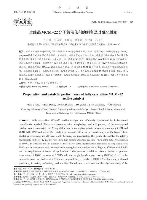
化工进展Chemical Industry and Engineering Progress2024 年第 43 卷第 1 期全结晶MCM-22分子筛催化剂的制备及其催化性能王一棪,王达锐,沈震浩,何俊琳,孙洪敏,杨为民(中石化(上海)石油化工研究院有限公司,绿色化工与工业催化全国重点实验室,上海 201208)摘要:采用水热晶化法高效合成了全结晶的MCM-22分子筛催化剂,利用X 射线衍射、扫描/透射电子显微镜、NH 3-TPD 等手段对催化剂的晶体结构、微观形貌、酸性质等进行了综合表征,并考察了催化剂在苯和乙烯液相烷基化制乙苯反应中的催化性能。
结果表明,该全结晶MCM-22分子筛催化剂在160℃条件下40h 即可完成晶化,相对结晶度达到100%。
制得的分子筛为薄片层状结构,由100%活性组分组成。
晶化后的催化剂成品仍维持条状形貌,机械强度达到82N/cm ,满足工业应用需求。
将该全结晶MCM-22分子筛催化剂应用于液相烷基化反应时,在反应温度180℃、反应压力3.5MPa 、乙烯质量空速1h -1、苯与乙烯摩尔比为2.5的条件下运行1000h ,催化剂表现出良好的反应活性、选择性和稳定性,乙烯转化率接近100%,乙基选择性约99.84%,重组分含量始终维持在1000μL/L 左右。
关键词:水热;结晶;分子筛;催化剂;苯中图分类号:O643.36;TQ426 文献标志码:A 文章编号:1000-6613(2024)01-0285-07Preparation and catalytic performance of fully crystalline MCM-22zeolite catalystWANG Yiyan ,WANG Darui ,SHEN Zhenhao ,HE Junlin ,SUN Hongmin ,YANG Weimin(State Key Laboratory of Green Chemical Engineering and Industrial Catalysis, Sinopec Shanghai Research Institute ofPetrochemical Technology Co., Ltd., Shanghai 201208, China)Abstract: Fully crystalline MCM-22 zeolite catalyst was efficiently synthesized by hydrothermal crystallization method. The crystal structure, micro morphology, and acid property of the as-prepared catalyst were characterized by X-ray diffraction, scanning/transmission electron microscopy (SEM and TEM), NH 3-TPD, and so on. The catalytic performance of the as-prepared catalyst in the liquid-phase alkylation of benzene and ethylene to ethylbenzene was investigated. The results showed that the relative crystallinity of MCM-22 zeolite with ultra-thin layered structure reached 100% after 40h crystallization at 160℃. In addition, the morphology of the catalyst after crystallization remained in strip shape with 100% active component, and the mechanical strength of the catalyst was as high as 82N/cm, which fully met the requirement of industrial application. Under reaction conditions close to industrial process: temperature of 180℃, pressure of 3.5MPa, ethylene weight hourly space velocity (WHSV) of 1h -1, molar ratio of benzene to ethylene of 2.5, the as-prepared fully crystallized MCM-22 zeolite catalyst showed good catalytic activity, selectivity, and stability. The ethylene conversion and the ethyl selectivity of the研究开发DOI :10.16085/j.issn.1000-6613.2023-1513收稿日期:2023-08-30;修改稿日期:2023-10-16。
![一种两步水热法合成小晶粒PZSM-5分子筛催化剂的方法[发明专利]](https://uimg.taocdn.com/30d6da0fb8f67c1cfbd6b820.webp)
专利名称:一种两步水热法合成小晶粒PZSM-5分子筛催化剂的方法
专利类型:发明专利
发明人:黄海,易明武,王大军,解建国,栾业志,李亭,杨文书,李延生,吕建宁
申请号:CN201310039126.5
申请日:20130131
公开号:CN103058209A
公开日:
20130424
专利内容由知识产权出版社提供
摘要:本发明涉及一种两步水热法合成小晶粒PZSM-5分子筛催化剂的方法,包括以下步骤:将硅源、钠盐和去离子水配制成溶液A;将铝源、酸和去离子水配制成溶液B;将磷源、去离子水配制成溶液C;将溶液B滴加到A中,加入有机模板剂,得到凝胶混合物,在搅拌下以5~10℃/h的速率升温至80℃~100℃,保持20~50小时得到混合物R;将溶液B滴加到A中,加入有机模板剂和溶液C,然后加入混合物R,以20~50℃/h升温至130℃~150℃,保持50~200小时,冷却,固液分离,洗涤、干燥、焙烧得到小晶粒PZSM-5分子筛;用无机酸进行离子交换,加入粘结剂,硝酸混合均匀,挤压成型,烘干、焙烧,得到产品。
与现有技术相比,本发明的PZSM-5分子筛催化剂用于甲醇转化制丙烯反应中显示了良好的丙烯选择性。
申请人:惠生工程(中国)有限公司
地址:201203 上海市浦东新区张江高科技园区张衡路1399号
国籍:CN
代理机构:上海科盛知识产权代理有限公司
代理人:蒋亮珠
更多信息请下载全文后查看。


分子筛催化剂的制备与催化性能研究分子筛催化剂是一类具有高度有序孔道结构的固体催化剂,其在化学工业中具有广泛的应用。
分子筛催化剂的制备和催化性能研究一直是催化领域的热点问题。
本文将从制备方法、表征手段和催化性能三个方面探讨分子筛催化剂的研究进展。
首先,分子筛催化剂的制备方法多种多样,常见的有溶胶-凝胶法、水热法、离子交换法等。
其中,溶胶-凝胶法是一种常用的制备方法,通过将溶胶中的金属离子或有机物与凝胶剂反应,形成固体凝胶,并经过干燥和煅烧等步骤得到分子筛催化剂。
水热法则是利用高温高压条件下的水热合成反应来制备分子筛催化剂。
离子交换法是通过将金属离子交换到分子筛的孔道中,形成金属分子筛催化剂。
这些制备方法各有优劣,选择适合的制备方法对于获得高性能的分子筛催化剂至关重要。
其次,分子筛催化剂的表征手段主要包括X射线衍射、扫描电子显微镜、透射电子显微镜等。
X射线衍射是一种常用的表征手段,通过测量样品对X射线的衍射图案来确定分子筛的晶体结构和晶格参数。
扫描电子显微镜和透射电子显微镜则可以观察到分子筛的形貌和孔道结构。
此外,还可以利用傅里叶变换红外光谱、氮气吸附等手段来研究分子筛的表面性质和孔道结构等。
最后,分子筛催化剂的催化性能研究是分子筛研究的核心内容之一。
分子筛催化剂的催化性能与其孔道结构、酸碱性质以及金属离子的状态等因素密切相关。
例如,分子筛的孔道结构对于反应物的扩散和产物的选择性有重要影响。
分子筛的酸碱性质则可以调控反应物的吸附和解离,影响催化反应的速率和选择性。
此外,金属离子的状态也会影响催化剂的催化性能,如金属离子的还原态和氧化态分别对应不同的催化反应。
在分子筛催化剂的催化性能研究中,还需要考虑反应条件、反应机理等因素。
通过调节反应条件,如温度、压力、反应物浓度等,可以优化催化反应的效果。
同时,通过研究反应机理,可以深入理解催化反应的过程和机制,为催化剂的设计和改进提供理论指导。
综上所述,分子筛催化剂的制备与催化性能研究是一个复杂而有挑战性的课题。

水热合成过程中Silicalite-1晶体形貌和尺寸的调控鲁慧彬;彭勇;王正宝【摘要】以气相SiO2为硅源、四丙基铵(TPA)为模板剂,水热合成了Silicalite-1分子筛,考察了合成液的水量、碱度(Na2O含量)、四丙基铵(TPA)含量和晶化条件(合成时间和搅拌方式)对Silicalite-1分子筛晶体形貌和尺寸的影响,采用X射线衍射(XRD)、扫描电镜(SEM)、激光粒度仪(LLS)等技术对合成的Silicalite-1分子筛晶体进行表征.结果表明,减少水量和增大碱度可以使Silicalite-1晶体由棺形转变为球形,但碱度过高或过低时,分子筛晶体的产率很低;增加TPA浓度和缩短晶化时间可以减小Silicalite 1分子筛晶体的粒径,且均能获得较高的收率;不同的搅拌方式会影响晶体的粒径大小和分布,转动式合成能够得到粒径较为均一的晶体,而搅拌式合成能得到粒径分布较广的晶体,粒径相对较小.因此,通过调节合成液组成和合成条件,可以控制Silicalite-1晶体的形貌和尺寸.【期刊名称】《石油学报(石油加工)》【年(卷),期】2016(032)003【总页数】7页(P461-467)【关键词】水热合成;Silicalite-1;形貌控制;晶粒尺寸;分子筛【作者】鲁慧彬;彭勇;王正宝【作者单位】浙江大学化学工程与生物工程学院,浙江杭州310027;浙江大学化学工程与生物工程学院,浙江杭州310027;浙江大学化学工程与生物工程学院,浙江杭州310027【正文语种】中文【中图分类】O643MFI型分子筛具有各向异性的三维孔道结构,其主孔道为十元环孔道,呈S型,孔径为0.51 nm×0.55 nm,而另一个十元环孔道呈直线型,孔径为0.54nm×0.56 nm[1]。
由于其独特的孔道结构、较好的水热稳定性以及疏水亲油的能力,MFI型分子筛已逐步成为石油化工领域的首选催化剂。
近年来,全硅型MFI分子筛的催化性能也得到了很多关注,Arudra等[2]以Silicalite-1为催化剂催化丁烯裂解反应,发现相对于有强酸性位的ZSM-5,Silicalite-1弱酸性位的存在更有利于得到丙烯,从而提高了反应的选择性。
Hydrocarbon steam reforming on Ni alloys at solid oxide fuel celloperating conditionsEranda Nikolla,Johannes W.Schwank,Suljo Linic*Department of Chemical Engineering,University of Michigan,2300Hayward Street,Ann Arbor,MI48109,United States1.IntroductionSteam reforming is a catalytic process for commercial hydrogenproduction.It is an endothermic reaction that involves theconversion of hydrocarbons and water into hydrogen and CO(1).In a catalytic reactor,this reaction is accompanied by theslightly exothermic water gas shift(WGS)reaction(2),whichconverts CO and steam into CO2and hydrogen.C n H mþn H2O)n COþnþmH2ðD H298>0Þ(1)COþH2O,CO2þH2ðD H298¼À41:2kJ=molÞ(2)Steam reforming is also important in direct utilization ofhydrocarbons in solid oxide fuel cells(SOFCs)[1–6].In SOFCs,H2iselectrochemically oxidized at the three-phase boundary(TPB)–TPB is the region where anode and electrolyte are in direct contactwith each other–resulting in the formation of steam,which theninternally reacts with the incoming fuel via steam reforming toform hydrogen and CO.Most steam reforming catalysts and SOFCanode electro-catalysts contain Ni metal supported on an oxide[7–9].Ni is the preferred catalytic material due to its excellent thermaland electronic characteristics,low cost,and high chemical activity.The ceramic oxide supports offer superior mechanical and thermalstability.One of the main issues with hydrocarbon steam reforming oversupported Ni catalysts is the deactivation of Ni due to theformation of carbon deposits.The carbon-induced deactivation ofNi has been studied extensively[7,10–26].For example,Rostrup-Nielsen and coworkers have reported that steam reforming ofvarious liquid fuels on Ni leads to rapid catalyst deactivation due tothe formation of encapsulating,whisker-like,or pyrolytic carbonon the catalyst[7,8,13].Multiple studies have been performed toelucidate the mechanism of the formation and growth of carbondeposits on Ni[11,17,20].For example,in situ transmissionelectron microscopy(TEM)studies have shown that duringmethane decomposition on Ni/MgAl2O4carbon nucleates at theunder-coordinated Ni surface sites[17].It was also shown that theextended carbon structures are formed in the process of thediffusion of C atoms and fragments on the surface of Ni and theirattachment to the carbon nucleation centers on the low-coordinated Ni sites.It is possible to circumvent the carbon-induced deactivation ofNi by increasing the steam to carbon ratio(S/C)in the feed.Whilethe presence of additional steam enhances the oxidation andremoval of carbon in the form of CO and CO2,it also increases themassflow rate through the reformer thus escalating the size of thereactor and capital cost.In addition,a substantial energy input isrequired to vaporize water and increase its temperature to theoperating conditions.Another disadvantage of the high inlet steamCatalysis Today136(2008)243–248A R T I C L E I N F OKeywords:SOFCDFTSteam reformingCarbon poisoningAlloysA B S T R A C TWe demonstrate that supported Sn/Ni alloy catalyst is more resistant to deactivation via carbondeposition than supported monometallic Ni catalyst in steam reforming of isooctane at moderate steamto carbon ratios,irrespective of the average size of metal particles and the metal loading.The experimentswere performed for average diameters of catalytic particles ranging from30to500nm and for theloading of active material ranging from15to44wt%with respect to the total mass of catalyst.The steamreforming reactions were performed at conditions that are consistent with typical solid oxide fuel cell(SOFC)operating conditions.DFT calculations show that the reasons for the enhanced carbon-toleranceof Sn/Ni compared to monometallic Ni are high propensity of Sn/Ni to oxidize carbon and lower drivingforce to form carbon deposits on low-coordinated metal sites.ß2008Elsevier B.V.All rights reserved.*Corresponding author.Tel.:+17346477984;fax:+17347647453.E-mail address:linic@(S.Linic).Abbreviations:DFT,density functional theory;TEM,transmission electronmicroscopy;STEM,scanning transmission electron microscopy;SOFC,solid oxidefuel cell;YSZ,8mol%yttria stabilized zirconia;EELS,electron energy loss spectro-scopy;SEM,scanning electron microscopy;EDS,energy dispersive X-ray spectro-scopy;XPS,X-ray photoelectron spectroscopy;XRD,X-ray diffraction.Contents lists available at ScienceDirectCatalysis Todayjournal homepage:/locate/cattod0920-5861/$–see front matterß2008Elsevier B.V.All rights reserved.doi:10.1016/j.cattod.2008.03.028concentration is that it reduces theflexibility to control the outlet CO/H2ratio.This approach is also not optimal for SOFCs since an increase in inlet steam concentration results in a decrease in the energy density of reactants.The introduction of steam also requires additional SOFC components(i.e.a water tank,preheating system to vaporize water),adding complexity to the system design and integration.In situ regeneration of the coked catalysts has also been explored to prevent irreversible carbon-induced deactivation[7,8]. In this process,non-aged,soft carbon,formed during steam reforming on Ni,is gasified by temporarily increasing the S/C ratio. The initial carbon formation on the catalyst is detected by performing a carbon balance on the system.The problem with this strategy is that,often,the formation of carbon deposits is rapid and even small amounts of carbon lead to the irreversible degradation of the active catalytic particles.This is especially problematic for SOFCs since the disintegration of the anode catalyst leads to the failure of the entire cell thus making the regeneration process impossible.Another approach to prevent carbon deactivation is to develop catalysts that are inherently more carbon-tolerant than Ni[19,27–33].For example,it has been suggested that metals such as Ru and Rh do not facilitate the formation of carbon deposits due to poor carbon solubility in these metals[13,34].However,Ru and Rh are prohibitively expensive.It has also been shown that the negative effect of carbon can be alleviated by selectively poisoning the low-coordinated Ni sites(carbon nucleation centers are formed on these sites)with small amounts of sulfur[14,16].Similarly,quantum chemical DFT calculations have predicted that Au/Ni surface alloys should exhibit an improved carbon-tolerance as compared to monometallic Ni[20,29].These predictions have been verified experimentally.It has also been shown that Cu supported on ceria is a stable SOFC anode electro-catalyst for the internal utilization of hydrocarbons over SOFCs[35,36].Compared to Ni-based electro-catalysts these materials are operated at lower temperatures due to the inferior thermal stability of Cu and ceria and thermal incompatibility of the ceria electro-catalyst and the8mol%yttria stabilized zirconia(YSZ)electrolyte.There are also reports in the patent literature suggesting that a large number of additives, including those mentioned below in the text(e.g.Sn),can be used to suppress the formation of carbon deposits on Ni[37].We have previously reported that the Sn/Ni catalysts exhibit improved carbon-tolerance with respect to monometallic Ni in steam reforming of multiple hydrocarbons at moderate S/C ratios [28,38].The studies were performed at external conditions that were consistent with the operation of SOFCs,i.e.,the operating temperature was1000–1100K.Furthermore,the loading of the active metal material(Ni or Sn/Ni)was$45wt%with respect to the total catalyst(active material plus support)and the average diameter of catalytically active particles was$0.5m m.In this contribution we have expanded on the previous studies demonstrating that Sn/Ni catalysts are more resistant to carbon than monometallic Ni for a wide range of metal loadings and particle size.2.Experimental2.1.Catalyst synthesis8mol%Yttria stabilized zirconia was prepared via a standard co-precipitation method[28].A mixture of yttrium nitrate (Y(NO3)3Á6H2O)and zirconyl chloride(ZrOCl2Á2H2O)dissolved in deionized water was precipitated using a solution of ammonium hydroxide.Afterfiltration and drying overnight,the precipitate was calcined at1073K for2h.We have used two different strategies,incipient wetness and ball milling,to introduce Ni on the YSZ support.The main difference between these synthesis strategies is that they yielded metal particles with significantly different diameters.These two approaches are generally utilized in the synthesis of steam reforming catalysts(incipient wetness)and anode electro-cata-lysts for SOFCs(ball milling).Therefore,we refer to catalysts synthesized with the incipient wetness and ball milling techniques as steam reforming and SOFC anode catalysts,respectively.The Ni/YSZ steam reforming catalyst was prepared by the incipient wetness technique.An equivalent of$15wt%of Ni with respect to the total amount of catalyst(Ni plus YSZ)in the form of Ni(NiO3)3was dissolved in ethanol and sequentially impregnated on the YSZ support.The catalyst was calcined in air at873K for2h and then reduced using a gas mixture of30%H2/N2at1073K for 5h.This procedure resulted in metal particles of$30nm,as measured by TEM and XRD,in diameter anchored on the support. The Sn/Ni/YSZ steam reforming catalyst was prepared by impreg-nating$3wt%of Sn,with respect to Ni,in the form of SnCl2Á4H2O on the calcined NiO/YSZ sample.The appropriate amount of SnCl2Á4H2O was dissolved in ethanol followed by sequential impregnation of the solution onto NiO/YSZ.The catalyst samples were then calcined again at873K for2h and reduced under a stream of30%H2/N2for5h at1073K.SOFC anode catalyst was prepared by ball milling a mixture of 50wt%YSZ and50wt%of NiO in methanol for24h.After drying, the powder was pressed into13mm diameter pellets at5000psi. The pellets were then sintered by ramping the temperature at2K/ min to1673K and keeping them at this temperature for4h.The catalyst was further reduced at1173K for5h in a gas mixture of 30%H2/N2to insure the full reduction of the pellets.This synthesis procedure yielded catalytic particles with$0.5m m diameter,as measured by TEM and XRD.The resulting catalysts had a Ni loading of44wt%.The Sn/Ni/YSZ SOFC anode catalyst was prepared by impregnating SnCl2Á4H2O($1wt%with respect to Ni)on the sintered NiO/YSZ pellets via the incipient wetness technique.The pellets were dried overnight at473K and then reduced under a stream of30%H2/N2for5h at1173K.In our reactor studies we have tested these catalysts in the powder and pellet form.The powder was produced by mechanically crushing the pellets.2.2.Reactor studiesThe reactor experiments were conducted isothermally at 1073K in a packed bed quartz reactor.The set-up included a set of massflow controllers for gas delivery,a pair of thermocouples (inside and outside the reactor),as well as peristaltic and syringe pumps for liquid delivery.The reactor effluent was analyzed using a Varian gas chromatograph(Varian CP3800)equipped with thermal conductivity detectors(TCD),aflame ionization detector (FID),and Hayesep P80/100,Molsieve13X45/60,Hayesep R80/ 100and Molsieve5A45/60columns.The mass of the catalysts and the totalflow rate were varied to obtain a gas hourly space velocity (GHSV)of0.05mol/g-min in a reactor with the diameter of0.5in.2.3.Scanning transmission electron microscopy(STEM),transmission electron microscopy(TEM),energy dispersive X-ray spectroscopy (EDS)and electron energy loss spectroscopy(EELS)JEOL2010F electron microscope was used for STEM,TEM,EDS and EELS studies.The instrument was operated at200kV under a pressure of1.5Â10À7Torr.The instrument is equipped with a zirconated tungsten(100)thermalfield emission tipfilament and a Gatan Imaging Filter(GIF)for electron energy loss spectroscopy experiments.The lens was conditioned for a probe size of aboutE.Nikolla et al./Catalysis Today136(2008)243–248 2440.2nm,with a convergence angle of13mrad and a collection angle of40mrad.The energy resolution(defined by the full width at half maximum of the zero loss peak)of the energy loss spectra is1.5eV at a dispersion of0.3eV per pixel.2.4.Density functional theory(DFT)The Dacapo pseudo-potentials plane wave code(http:// www.camp.dtu.dk)was employed for all calculations.Our approach was tofind a set of parameters that ensured the relative convergence,i.e.,the convergence of the relative energies of various structures.With this set of parameters we have been able to reproduce various properties such as carbon atom adsorption energies,oxygen adsorption energies,graphene sheet adsorption energy on Ni(111),and activation barrier for the attachment of a C atom to the graphene sheet over Ni(111)reported previously by others[11,16,24].For model systems with the(111)surface termination,we used a3Â3supercell with four layers of metal atoms.We utilized18special Chadi-Cohen k-points to sample the Brillouin zone.The calculations for the(211)surface termination were performed using slabs with nine layers of metal organized in 1Â3supercells.Monkhorst-Pack mesh with a3Â3Â1k-point grid was employed to sample the Brillouin zone.Adsorbates were adsorbed on one side of a slab.Approximately,15A˚of vacuum separated the slabs,and a dipole-correction scheme was employed to electro-statically decouple the slabs.Electron exchange correla-tion effects were described using the generalized gradient approximation(GGA)with the Perdew–Wang91(PW91)functional [39,40].Vanderbilt pseudo-potentials were employed to describe core electrons[41].The density of valence electrons was determined self-consistently by iterative diagonalization of Kohn-Sham Hamil-tonian using Pulay mixing of densities.The plane wave basis set used to describe the one-electron states was cut off at350eV.An electronic temperature(k b T)of0.1was utilized during calculations with thefinal results extrapolated to0K.In the geometry optimization calculations on the(111)surface termination,the two top substrate layers and adsorbates were allowed to relax in the z direction.On the(211)termination,the two top substrate layers were allowed to relax in the x(normal to the direction if the step-edge)and z directions.The forces were minimized to0.05eV/A.3.ResultsWe have previously reported a number of experimental and theoretical studies aimed at characterizing the Sn/Ni/YSZ catalyst [38].These characterization studies indicated that the impregna-tion of Ni particles with a small amount of Sn results in the formation of Sn/Ni surface alloys.The surface alloy is characterized by Sn mixing with Ni in the surface layers of the particle.For example,DFT calculations showed that the free energy of formation for the Sn/Ni surface alloy is lower than the formation energy of other Sn/Ni structures,including Sn dissolved in Ni bulk or separated phases of pure Sn and Ni[38].The predictions of DFT calculations have been verified experimentally[38].For instance, we utilized X-ray photoelectron spectroscopy(XPS)to determine that the atomic concentration of Sn in the surface layers of the reduced Sn/Ni catalytic particles was$25%for the Sn/Ni particles that contained$1wt%of Sn with respect to Ni.These particles were approximately50nm in diameter[28,38].Furthermore, scanning electron energy loss spectroscopy measurements showed that Sn preferentially segregates towards the surface of Sn/Ni particles.For example,Fig.1b and c shows the electron energy loss spectra corresponding to the Sn M-edge and Ni L-edge obtained for an electron beam focused on a region close to the boundary of a Sn/ Ni particle and a region close to the center of the particle.Fig.1b and c demonstrate that the ratio of the Sn M-edge to Ni L-edge is higher at the boundary of the particle and it decreases as the electron bean is moved closer to the center of the particle.These results provide further evidence that there is an enrichment of Sn close at the surface of the Sn/Ni particles.Furthermore,our energy dispersive X-ray spectroscopy and temperature programmed reduction(TPR)measurements also corroborated the results discussed above suggesting the formation of Sn/Ni surface alloy [28,38].It is important to note that the amounts of Sn and Ni required to form the Sn/Ni surface alloys depends critically on the size of catalytic particles,i.e.,on the particle surface to volume rge particles require less Sn with respect to Ni compared to smaller catalytic particles.Fig.2shows the conversion of isooctane as a function of time in steam reforming of isooctane at a steam to carbon(S/C)ratio of 1.5and an operating temperature of1073K for fourdifferentFig.1.(a)Scanning transmission electron micrograph(STEM)of a3%Sn/15%Ni/YSZ(3wt%of Sn with respect to Ni,15wt%of Ni with respect to the total catalyst)particle. Electron energy loss spectrum(EELS)of the Sn M-edge and Ni L-edge for an electron beam focused on(b)a region close to the boundary of the particle and(c)a region close to the center of the particle.E.Nikolla et al./Catalysis Today136(2008)243–248245catalysts:(1)15%Ni/YSZ (15wt%Ni loading with respect to the total catalyst (Ni and YSZ)and average particle diameter of 30nm),(2)3%Sn/15%Ni/YSZ (15wt%Ni loading with respect to the total catalyst,3wt%Sn with respect to Ni,and average particle diameter of 30nm),(3)44%Ni/YSZ (44wt%Ni with respect to the catalyst mass and an average particle diameter of 0.5m m),and (4)1%Sn/44%Ni/YSZ (44wt%Ni with respect to Ni plus YSZ,1wt%of Sn with respect to Ni,and an average particle diameter of 0.5m m).The procedures used to synthesize these catalysts are described above.Fig.2shows that the conversion of isooctane for both Sn/Ni/YSZ catalysts,irrespective of metal loading and average particle diameter,was stable for as long as the catalyst was kept on stream.The longest tests lasted for approximately 5days.In contrast to the Sn/Ni/YSZ catalysts,the conversion of isooctane on monometallic Ni supported on YSZ deteriorated over time for both Ni/YSZ catalysts.The reactor tests also showed that the Ni/YSZ catalyst with smaller Ni particles (15%Ni/YSZ)was more resistant to carbon than the Ni/YSZ catalyst with larger metal particles (44%Ni/YSZ)for identical operating conditions.These observations have also been made by others and are generally attributed to the high energy of the carbon deposits,mainly carbon nano-fibers,formed in the process of catalyst deactivation [8,26,42,43].The high energy of carbon deposits results in a lower driving force to form these deposits on smaller Ni particles compared to larger particles.Electron microscopy studies performed on used Ni/YSZ catalysts showed that the deactivation of Ni/YSZ was a conse-quence of the formation of carbon deposits which led to the disintegration of Ni particles.For example,Fig.3a shows a scanning electron micrograph and a transmission electron micrograph of a used 44%Ni/YSZ catalyst.It is clear that the catalytic particles were completely covered by carbon.Fig.3b shows SEM and STEMimages of used 1%Sn/44%Ni/YSZ.Unlike for the Ni/YSZ catalyst,no carbon deposits were detected on 1%Sn/44%Ni/YSZ.We have also utilized XPS to further characterize the used catalysts [28,38].These measurements showed that a substantial amount of graphitic carbon was formed on the 44%Ni/YSZ catalyst during isooctane steam reforming.On the other hand no significant carbon deposition was detected on the 1%Sn/44%Ni/YSZ catalyst.Similar results showing that monometallic Ni catalysts deactivated due to the formation of extended carbon structures on Ni were also obtained for the catalytic particles with smaller diameter and metal loading,mainly 15%Ni/YSZ and 3%Sn/15%Ni/YSZ catalysts.4.DiscussionThe results presented above show that,irrespective of metal loading or the size of catalytic particles,the Sn/Ni catalysts are more carbon-tolerant than monometallic Ni in steam reformingofFig.2.Isooctane conversion in steam reforming of isooctane at S/C ratio of 1.5and 1073K for:(a)15%Ni/YSZ catalyst (15wt%of Ni with respect to the total catalyst)and a 3%Sn/15%Ni/YSZ catalyst (3wt%of Sn with respect to Ni,15wt%of Ni with respect to the total catalyst).Both catalysts had an average metal particle diameter of $30nm,(b)44%Ni/YSZ catalyst (44wt%of Ni with respect to the total catalyst)and a 1%Sn/44%Ni/YSZ catalyst (1wt%Sn with respect to Ni).Both catalysts had an average metal particle diameter $500nm.Fig.3.(a)SEM and TEM (insert)images of a 44%Ni/YSZ catalyst after steam reforming of isooctane.This process resulted in the formation of carbon filaments.(b)SEM and STEM (insert)images for a 1%Sn/44%Ni/YSZ catalyst after steam reforming of isooctane.No carbon was detected on thecatalyst.Fig.4.(a)DFT-calculated reaction energies for elementary steps in steam reforming of methane on Ni(111).E.Nikolla et al./Catalysis Today 136(2008)243–248246isooctane at moderate S/C ratios.These observations suggest that Sn/Ni could be a more carbon-resistant alternative to Ni for catalytic hydrogen production from hydrocarbons and for the direct utilization of hydrocarbon fuels in SOFCs.In the next paragraphs,we will identify the underlying molecular principles,grounded in first principles DFT calculations,which could explain the improved carbon-tolerance of Sn/Ni as compared to mono-metallic Ni.It is generally accepted that at high operating temperature (1000–1200K)hydrocarbon molecules rapidly decompose on Ni forming adsorbed carbon fragments and hydrogen atoms [20].In addition,steam activation results in the formation of adsorbed O*and OH*.For example,in Fig.4we show the reaction energies,calculated using DFT,for various elementary steps involved in steam reforming of methane on Ni(111).The figure shows that on Ni(111)the adsorbed CH x fragments with the lowest energy are C*and CH*.Our DFT calculations also indicate that there exists a strong thermodynamic diving force for C*and CH*to further react with O*or OH*to form adsorbed CO*,or to react with each other to form graphitic carbon deposits.It is important to recognize that the formation of CO on Ni provides a pathway for the removal of the C atoms from the catalyst surface in the process of further oxidation of CO to form gas phase CO 2.On the other hand the formation of carbon deposits on Ni results in the deactivation of the Ni catalyst.These observations are fairly consistent for different hydrocarbons and also for different surface terminations of Ni with one exception,that on the low-coordinated sites of Ni,for example the step-edge sites on Ni(211),the CH*would be less thermo-dynamically stable than separated C*and H*.The mechanism of elementary steps shown in Fig.4suggests that one can formulate the problem of carbon deactivation in terms of the selectivity associated with the formation of C–O versus C–C bonds on Ni.In order to prevent the carbon-induced deactivation,a catalyst should be able to selectively oxidize C atoms rather than form C–C bonds.Fig.5shows the DFT-calculated potential energy surfaces for the oxidation of a C atom and for the attachment of a C atom to a carbon nucleation center (C–C bond formation)on the (111)surface of Ni and the Sn/Ni surface alloy.The carbon nucleation center was modeled as a collection of carbon atoms on Ni assembled in the geometry corresponding to the lowest energy.The DFT calculations indicate that on Ni(111)the potential energy surfaces associated with the C–C and C–O bond formation are very similar to each other.On the other hand,on the Sn/Ni surface alloy,as modeled in Fig.5,the overall activation barrier for the C atom oxidation is much lower than the overall activation barrier for the C–C bond formation.The change in the overall activation barrier is a consequence of the increased barrier for the diffusion of C atoms on the Sn/Ni surface alloy.Similar conclusions were obtained for the diffusion of CH*fragment on these surfaces.The DFT-calculated potential energy surface for the diffusion of CH*andO*Fig.5.(a)DFT-calculated potential energy surfaces for C–C bond formation on Ni(111)and Sn/Ni(111).Inserts show the lowest energy pathways for the attachment of a C atom to a carbon nucleation center (modeled as a chain of carbon atoms)on the two surfaces shown in the insert,(b)C–O bond formation on Ni(111)and Sn/Ni(111).Inserts show the lowest energy pathways for the two surfaces shown in the insert.Ni is depicted as large blue (light)atom,Sn as a large purple atom,carbon chain as a chain of small blackatoms.Fig. 6.DFT-calculated diffusion pathways for O and CH on Ni(111)and Sn/Ni(111).Inserts show the lowest energy pathways.On Ni(111),the lowest energy pathway for both.O and CH,is the ABCDEFG path.On the Sn/Ni(111)model system,the lowest energy pathway for O is the ABCDEFG path,while CH follows the AB123FG pathway.Ni is depicted as a large blue (light)atom and Sn is depicted as a large purpleatom.Fig.7.DFT-calculated adsorption energies per carbon atom for a C atom,C 8cluster,and a graphene chain adsorbed on Ni(211)and Sn/Ni(211).More negative energies suggest more exothermic adsorption process.E.Nikolla et al./Catalysis Today 136(2008)243–248247on Ni(111)and Sn/Ni(111)model alloy are shown in Fig.6.It is clear that,in contrast to Ni(111),the barrier for the diffusion of CH*on the Sn/Ni surface alloy is significantly larger that the barrier for the diffusion of O*.These DFT studies indicated that on the Sn/ Ni surface alloy,as opposed to monometallic Ni,the oxidation of carbon is kinetically preferred compared to the formation of C–C bonds.DFT calculations have also demonstrated that in addition to the enhanced capacity to oxidize C atoms,the Sn/Ni surface alloy also lowers the thermodynamic driving force associated with the formation of carbon nucleation centers at the low-coordinated Ni sites.We note that recent in situ TEM studies and DFT calculations have shown that carbon nucleates on low-coordinated Ni sites [17].DFT calculated adsorption energies for various carbon nucleation centers(a carbon atom,a cluster of eight carbon atoms,and a graphene chain)on monometallic Ni and Sn/Ni surface alloy are shown in Fig.7.Thefigure shows that for all carbon structures,the under-coordinated sites on Ni(to model these sites,the Ni(211)surface was used)bind carbon more strongly than the under-coordinated sites on Sn/Ni(211).The reason for this is that Sn atoms break the ensembles of low-coordinated Ni sites,which interact strongly with carbon,there-fore lowering the propensity of these sites to nucleate extended carbon networks.5.ConclusionWe showed that Sn/Ni/YSZ catalyst is more carbon-tolerant than Ni/YSZ in steam reforming of isooctane at moderate S/C ratios, irrespective of the average size of metal particles and the metal loading.Our DFT calculations have suggested that the reasons for the enhanced carbon-tolerance of Sn/Ni compared to monome-tallic Ni are:(i)high propensity of Sn/Ni to oxidize carbon and(ii) lower driving force to form carbon deposits on low-coordinated metal sites.AcknowledgementsWe gratefully acknowledge the support of DOE-NETL(FC26-05-NT-42516and FC26-06NT42813),DOE-BES,Division of Chemical Sciences(FG-02-05ER15686),and DOE FG02-06CH11300.Super-computing time at SDSC and Dr.Kai Sun’s help with electron microscopy is greatly appreciated.References[1]E.Achenbach,E.Riensche,J.Power Sources52(1994)283–288.[2]A.Atkinson,S.Barnett,R.J.Gorte,J.T.S.Irvine,A.J.Mcevoy,M.Mogensen,S.C.Singhal,J.Vohs,Nat.Mater.3(2004)17–27.[3]A.L.Dicks,K.D.Pointon,A.Siddle,J.Power Sources86(2000)523–530.[4]shtabeg,S.J.Skinner,J.Mater.Chem.16(2006)3161–3170.[5]J.R.Rostrup-Nielsen,J.B.Hansen,S.Helveg,N.Christiansen,A.K.Jannasch,Appl.Phys.A:Mater.Sci.Process.85(2006)427–430.[6]J.Mukherjee,S.Linic,J.Electrochem.Soc.154(2007)B919–B924.[7]J.R.Rostrup-Nielsen,Catalytic steam reforming,Catalysis-Science and Technol-ogy,vol.5,Springler,Berlin,1984.[8]J.R.Rostrup-Nielsen,J.Sehested,J.K.Norskov,Adv.Catal.47(47)(2002)65–139.[9]J.M.Wei,E.Iglesia,J.Catal.224(2004)370–383.[10]H.Timmermann,D.Fouquet,A.Weber,E.Ivers-Tiffee,U.Hennings,R.Reimert,Fuel Cells6(2006)307–313.[11]F.Abild-Pedersen,J.K.Norskov,J.R.Rostrup-Nielsen,J.Sehested,S.Helveg,Phys.Rev.B73(2006).[12]J.R.Rostrup-Nielsen,Phys.Chem.Chem.Phys.3(2001)283–288.[13]J.R.Rostrup-Nielsen,T.S.Christensen,I.Dybkjaer,Recent Adv.Basic Appl.AspectsInd.Catal.113(1998)81–95.[14]J.R.Rostrup-Nielsen,J.Catal.85(1984)31–43.[15]J.R.Rostrup-Nielsen,L.J.Christiansen,Appl.Catal.A:Gen.126(1995)381–390.[16]F.Abild-Pedersen,O.Lytken,J.Engbaek,G.Nielsen,I.Chorkendorff,J.K.Norskov,Surf.Sci.590(2005)127–137.[17]S.Helveg,C.Lopez-Cartes,J.Sehested,P.L.Hansen,B.S.Clausen,J.R.Rostrup-Nielsen,F.Abild-Pedersen,J.K.Norskov,Nature427(2004)426–429.[18]D.L.Trimm,Catal.Today37(1997)233–238.[19]D.L.Trimm,Catal.Today49(1999)3–10.[20]H.S.Bengaard,J.K.Norskov,J.Sehested,B.S.Clausen,L.P.Nielsen,A.M.Molen-broek,J.R.Rostrup-Nielsen,J.Catal.209(2002)365–384.[21]T.Takeguchi,Y.Kani,T.Yano,R.Kikuchi,K.Eguchi,K.Tsujimoto,Y.Uchida,A.Ueno,K.Omoshiki,M.Aizawa,J.Power Sources112(2002)588–595.[22]N.C.Triantafyllopoulos,S.G.Neophytides,J.Catal.217(2003)324–333.[23]C.M.Finnerty,N.J.Coe,R.H.Cunningham,R.M.Ormerod,Catal.Today46(1998)137–145.[24]R.M.Watwe,H.S.Bengaard,J.R.Rostrup-Nielsen,J.A.Dumesic,J.K.Norskov,J.Catal.189(2000)16–30.[25]I.Alstrup,M.T.Tavares,C.A.Bernardo,O.Sorensen,J.R.Rostrup-Nielsen,Mater.Corros.49(1998)367–372.[26]X.Y.Chen,A.R.Tadd,J.W.Schwank,J.Catal.251(2007)374–387.[27]J.Xu,M.Saeys,J.Catal.242(2006)217–226.[28]E.Nikolla,A.Holewinski,J.Schwank,S.Linic,J.Am.Chem.Soc.128(2006)11354–11355.[29]F.Besenbacher,I.Chorkendorff,B.S.Clausen,B.Hammer,A.M.Molenbroek,J.K.Norskov,I.Stensgaard,Science279(1998)1913–1915.[30]N.Nichio,M.L.Casella,G.F.Santori,E.N.Ponzi,O.A.Ferretti,Catal.Today62(2000)231–240.[31]O.Sidjabat,D.L.Trimm,Top.Catal.11(2000)279–282.[32]J.W.Shabaker,G.W.Huber,J.A.Dumesic,J.Catal.222(2004)180–191.[33]J.W.Shabaker,D.A.Simonetti,R.D.Cortright,J.A.Dumesic,J.Catal.231(2005)67–76.[34]J.J.Strohm,J.Zheng,C.S.Song,J.Catal.238(2006)309–320.[35]R.J.Gorte,J.M.Vohs,J.Catal.216(2003)477–486.[36]H.Kim,C.Lu,W.L.G.Worrell,R.J.J.M.Vohs,J.Electrochem.Soc.149(2002)A247–A250.[37]I.Ul-Haque,D.L.Trimm,Process for Steam Reforming of Hydrocarbons,HaldorTopsoe,1997.[38]E.Nikolla,J.Schwank,S.Linic,J.Catal.250(2007)85–93.[39]J.Perdew,in:P.Ziesche,H.Eschrig(Eds.),Electronic Structure of Solids’91,Akademie Verlag,Berlin,1991,pp.11–20.[40]J.P.Perdew,Phys.Rev.B:Condens.Matter33(1986)8822.[41]D.Vanderbilt,Phys.Rev.B41(1990)R7892.[42]J.Rostrup-Nielsen,J.K.Norskov,Top.Catal.40(2006)45–48.[43]B.D.Gould,X.Y.Chen,J.W.Schwank,J.Catal.250(2007)209–221.E.Nikolla et al./Catalysis Today136(2008)243–248 248。
简单水热合成法制备介孔ZSM-5分子筛
周颖,张利雄
【摘要】摘要:本文以NaOH、四丙基漠化披(TPABr)、AI2(SO4)318H2O 和硅溶胶(SiO2-sol)为原料,采用水热合成法,通过简单的原料比例调变,制备具有介孔结构的ZSM-5分子筛,考察合成配方中水含量、Si含量、AI含量和TPABr含量对介孔、形貌的影响。
采用X线衍射仪(XRD)、傅里叶变换红外光谱仪(FT-IR)、扫描电子显微镜(SEM)和N2吸附-脱附等对样品进行表征。
结果表明:在前驱液摩尔配比n(SiO2): n(AI2O3): n(Na2O): n(TPABr): n(H2O)=100 :1: 8.75 :12 : 2 600的情况下,于180 °C下反应36 h,可制得直径为18 ~ 20 pm的球形ZSM-5 分子筛,分子筛表面由二级纳米晶粒堆砌而成,总比表面积为371 m2/g,介孔率为32.1%,介孔孔径为2.0 nm。
水含量的增加和Si含量的降低分别有助于二级晶粒更为紧密地堆积和向长条状生长,而AI和TPABr含量的增加则会导致颗粒难以成型且颗粒的尺寸的减小。
另外,水和AI含量的增加及Si含量的降{氐会导致样品总孔容、介孔率和孔径的减小,而样品比表面积则随水含量的降低及Al、Si含量的増加而减小。
TPABr含量的调变对样品介孔性质影响不大。
【期刊名称】南京工业大学学报(自然科学版)
【年(卷),期】2016(038)001
【总页数】9
【关键词】ZSM-5沸石;介孔分子筛;水热合成
沸石分子筛以独特的微孔结构和优良的催化性能被广泛应用于精细化工和石油
化工等领域[1 ~ 2],但微孔结构不利于大分子的扩散[3],限制了它在大分子参与的。
水热晶化法合成介孔氧化铝分子筛研究
水热晶化法是一种常用的方法来合成介孔氧化铝分子筛。
在这个方法中,主要的原料是铝盐和有机模板剂,并且需要在水热条件下进行反应。
具体步骤如下:
1. 溶解合适量的铝盐(如硝酸铝)和有机模板剂(如正硅酸酯)在适当的溶剂中,通常是水或有机溶剂。
2. 将溶液转移到一个加热反应容器中,并进行水热处理。
水热温度通常在80-200℃之间,持续时间为数小时至数天。
3. 在水热过程中,由于有机模板剂的存在,形成了介孔结构,并且氧化铝晶体开始生长。
4. 反应结束后,将产物分离出来,并进行洗涤和干燥处理。
5. 最后,通过焙烧过程,将有机模板剂热解并去除,形成介孔氧化铝分子筛。
研究介孔氧化铝分子筛的合成可以涉及不同的实验条件和反应参数的优化,以获得具有理想晶体结构和孔道尺寸的样品。
此外,也可以利用其他表征手段,如X射线衍射、扫描电子显
微镜等,来研究样品的结构和性质。
水热法制备铝硅酸钠分子筛实验报告分子筛是一种具有特殊结构和性质的材料,具有广泛的应用前景,尤其是在化学催化和分离过程中。
铝硅酸钠分子筛是一种常见的分子筛,具有高度有序的孔道结构和大的比表面积,可用于催化反应和分离过程中。
水热法是一种制备分子筛的方法,通过在高温高压下将硅源、铝源和碱源混合反应,形成铝硅酸钠分子筛。
本实验旨在通过水热法制备铝硅酸钠分子筛,并对其物理化学性质进行表征。
二、实验原理铝硅酸钠分子筛是一种由SiO4和AlO4四面体交替组成的三维骨架结构,其中钠离子位于孔道中心。
水热法制备铝硅酸钠分子筛的过程中,硅源和铝源在碱性条件下形成硅酸和铝酸,随后与钠离子结合形成铝硅酸钠分子筛。
实验中使用的硅源为硅酸钠,铝源为氢氧化铝,碱源为氢氧化钠。
将这些原料混合,并在高温高压下反应,可制备出铝硅酸钠分子筛。
反应过程中,硅酸钠和氢氧化铝在碱性条件下反应,生成硅酸和铝酸,随后这些化合物与氢氧化钠反应,形成铝硅酸钠分子筛。
三、实验步骤1. 准备实验器材和试剂,称取硅酸钠、氢氧化铝和氢氧化钠,按一定比例混合。
2. 将混合物加入到高压釜中,加入适量的水,密封高压釜。
3. 放入恒温槽中,在恒温槽中升温,并保持一定时间。
4. 升温结束后,将高压釜取出,冷却并打开高压釜,取出制备好的铝硅酸钠分子筛。
5. 对制备的铝硅酸钠分子筛进行物理化学性质表征,包括比表面积、孔径大小等。
四、实验结果与分析通过水热法制备的铝硅酸钠分子筛样品,经过扫描电子显微镜和X射线衍射分析,得到了以下结果:1. SEM图像显示铝硅酸钠分子筛呈现出典型的球形粒子形态,粒径分布较为均匀。
粒径大小约为2-3微米。
2. XRD分析显示铝硅酸钠分子筛具有典型的分子筛晶体结构,具有高度有序的孔道结构和大的比表面积。
孔径大小约为0.5-2纳米。
3. BET比表面积测试结果显示铝硅酸钠分子筛的比表面积为300-400平方米/克。
以上结果表明,本实验成功制备出了铝硅酸钠分子筛,并对其物理化学性质进行了表征。