松下以太网设置方法介绍
- 格式:docx
- 大小:230.76 KB
- 文档页数:4
QUICK SETUP GUIDE Controller (Network Adaptor)Model No.CZ-TACG1LanguageEnglish (UK) (3)B. Malaysia (21)Bulgarian (39)Danish (57)Deutsch (German) (75)Finnish (93)Francais (111)Italiano (129)Norwegian (147)Turkish (165)Spanish (183)Swedish (201)Thai (219)Vietnamese (237)Indonesia (255)23E n g l i s Safety Precautions ..............................................4 ~ 6System Overview .......................................................7Before Installing the Adaptor ...................................7Parts Identi fi cation ....................................................8Parts............................................................................9Adaptor Installation .................................................10Connecting Network ................................................11Starting Panasonic AC controller ..........................12Troubleshooting ......................................................18Information ...............................................................19Firmware Update Function .....................................20Software License Information (274)Model No.CZ-T ACG1Thank you for purchasing this Panasonic product.Please read these instructions carefully before using this product, and savethis manual for future use.QUICK SETUP GUIDEController (Network Adaptor)Safety PrecautionsRead the following “SAFETY PRECAUTIONS” carefully before installation.Electrical work must be installed by a licensed electrician. Be sure to use the correct rating and main circuit for the model to be installed.The caution items stated here must be followed because these important contents are related to safety. The meaning of each indication used is as below. Incorrect installation due to ignoring of the instruction will cause harm or damage, and the seriousness is classifi ed by the following indications.Please provide this setup guide to the user afterinstallation. Instruct user to keep it with the instructionEnglis Do not touch with wet hands.-This can cause electric shock or ignition due toshorting.Do not set up in hospitals or places where electronic medical devices are located.-Radio waves emitting from this adaptor mayinterfere with electronic medical devices andcause them to malfunction.Do not set up where children can reach the adaptor.-They may pull on it or cause themselves aninjury.Do not wipe with wet cloths or wash in water.-This can cause electric shock or ignition.6 Ensure cables are installed properly so that external forces cannot affect them.-Not doing so may cause overheating which canlead to ignition.Stop use as soon as you notice any problems or malfunctions and shut off the electric supply to the connected appliance.-Not doing so may cause smoke, ignition, electricshock, or burns.-Examples of problems and malfunctions• There is a burning smell• Water or a foreign object has gotten insideImmediately request repair from the place of purchase or the installer.7E n g l i sSystem OverviewIndoor unitNetworkadaptorCZ-T ACG1Wireless LANBefore Installing the Adaptor•Requires a Smartphone that is iOS/Android compatible;•The Network adaptor (adaptor) is designed specifi cally as a terminal for the Panasonic AC controller;•Do not attach the adaptor to metal as wireless performance will be adversely affected;•The adaptor must be installed outside of the indoor unit. (It needs to be accessed when connecting it or when there is a problem.);•The Wireless LAN network coverage must include the air conditioner installation location;•Do connect the Wireless LAN to a compatible Panasonic Air Conditioner with a connectivity interface port.Specifi cationInput Voltage DC 12V (From air conditioner indoor unit) Power consumption Max: 660 mWSize66 mm (H) x 36 mm (W) x 12 mm (D)Weight Approx. 85gInterface1x Wireless LANWireless LAN standard IEEE 802.11 b/g/nFrequency range 2.4 GHz bandEncryption WPA2-PSK (TKIP/AES)8Parts Identi fi cation54321No Item Description1Power LED Indicates that the adaptor is being suppliedwith power.2Link LED Indicate the communication status of adaptor to the server.3Status LEDIndicate the communication status of adaptor to the air-conditional.Green: status without weekly timer Orange: status with weekly timer Red: AbnormalityRed → Orange → Green : Auto updatingadaptor fi rmware During signal strength checking:-Strong: Medium: Weak: No signal: 4Setup Switch*Connection setup mode switching5Check Switch*Signal strength checking (press and hold for 5 seconds then release)Disable LEDs display (press and hold for 10 seconds then release)6Reset*Soft reset* The device factory reset can be done by press and hold CHECK and SETUP button for 10 seconds. After release the CHECK and SETUP button, press the reset button.9E n g l i sParts10Adaptor Installation1. Attach the Adaptor unit with double-sided adhesive tape on the wall near the indoor unit.-Shut off the power supply when installing this adaptor. -Make sure the wall is clean and free from dirt.Adaptor Adhesive tape Wall2. Use the cord clamp to fi x the cable to the wall.Pull the cable around as shown in the diagram so that the external forcecannot act on the connector in the adaptor. Furthermore, on the indoor unit end, use the included cable tie to fix the cables together when necessary.Generalillustration for installation use3. Connect the cable to the CN-CNT connector at the indoor unit.T ake note each indoor unit CN-CNT connector location might be different. Please consult authorized dealer.E n g l i s Connecting NetworkEstablish network connection to the internet via Wireless mode.1. Turn on the power supply to the indoor unit.-The Power LED lights (green).-The Status LED blinking (green).2. Download and install the Panasonic AC controller.3. Follow the instruction of the app to complete the installationsetup. Refer to next page.-All LEDs lights (green).Starting Panasonic AC controllerUse a Smartphone that is iOS/Android compatible.•User interface image may change without notifi cation.•There is no charge for using this application. However, other charges may be incurred for connection and operation.•Updates to the service may mean there are changes to the design of the screen and display.1. Login to the Panasonic AC controllerLogin with your Panasonic ID and password.Panasonic ID can be registered free from the link onthe page or at the following URL.(https:///Account/Register001)2. Connection Guidei. At My Home screen, tap “+” to add new product.ii. Select the product that you want to add.iii. Tap “Start” to begin the connection setup.Englis iv. T ap “Next” after confi rming the POWER LED ofthe network adaptor is ON.v. If you are the fi rst user (administrator) to operate the air conditioner via this application, reset the network adaptor with a pin and tap “Next”.vi. Choose the button that matches the status of LINK LED on the network adaptor.vii. T ap on the preferred connection setup mode.-T o “Connect with WPS mode”, proceed toinstruction 3.1 (For router that supports WPS)-T o “Connect with AP mode”, proceed toinstruction 3.2 (For router that does not supportWPS)i. Press the “WPS” button on the router to establishconnection.ii. Tap “Next” after the router is ready for connection. iii. Press and hold the “SETUP” button on the network adaptor for 5 seconds.iv. Release the “SETUP” button when both STATUS LED and LINK LED start to blink. T ap “NEXT”.v. Wait until LINK LED is ON indicates theconnection setup is complete. T ap “NEXT” andproceed to instruction 4.Englisi. Press and hold the “SETUP” button on the network adaptor for 10 seconds.ii. Release the “SETUP” button when the ST ATUSLED starts to blink in orange.iii. T ap “NEXT”.iv. T ap “T o wireless network settings of thesmartphone” to change the wireless networkconnection of the smartphone to the followingnetwork, the smartphone will connect to thenetwork adaptor.SSID: Panasonic-CZ-T -wirelessAP Password: Rac8pswav. A window will prompt, tap “Copy password andnext” to proceed to smartphone wireless networksetting.vi. Connect to “Panasonic-CZ-T -wirelessAP” networkand back to the application to continue with thesetup.vii. Tap “T o wireless network setting” to setup the wireless network connection of the networkadaptor.viii. Connect the network adaptor to wireless router.Select your wireless router.ix. Enter the password of the selected wireless router.x. The LINK LED will light up when the network adaptor successfully connects to the server.T ap “NEXT” and proceed to instruction 4.* D uring network adaptor connecting to wirelessrouter, STATUS LED and LINK LED will blinksimultaneously.E n g l i s 4. Setup completioni. Input the Device ID. Device ID is written at nameplate attached to the network adaptor or labelattached on the packaging.ii. Set the password for the network adaptor.iii. T ap “Register” to complete the setup.iv. Y ou can name the air conditioner unit to help youidentify e the Panasonic AC controllerUser's manual can be found under Menu tab.The Panasonic AC controller is connected to thenetwork adaptor and ready for use.TroubleshootingWhen the power LED does not light up(no power supply to the adaptor)Check the power supply.Check the connection of the cable.When the status LED does not light up(Adaptor can’t communicate with air-conditioner)Check the connection of the cable.The connection between your device and a client through wireless network cannot be established.Ensure that the wireless network function is enabled.Refresh the network list and select the correct SSID.Check the IP address, and ensure that your client can automaticallyobtain an IP address.Enter the correct network key (wireless network password) when you connect with AP mode.Reset device Password(In case you forgot the device Password)Remove the device from device list and add back the device.Factory reset the device and add back the device. The device factoryreset can be done by press and hold CHECK and SETUP button for 10 seconds. After release the CHECK and SETUP button, press the reset button.E n g l i sThese symbols on the products, packaging, and/or accompanying documents mean that used electrical and electronic products and batteries should not be mixed with general household waste.For proper treatment, recovery and recycling of old products and used batteries, please take them to applicable collection points, in accordance with your national legislation and the Directives 2002/96/EC and 2006/66/EC.By disposing of these products and batteries correctly, you will help to save valuable resources and prevent any potential negative effects on human health and the environment which could otherwise arise from inappropriate waste handling.For more information about collection and recycling of old products and batteries, please contact your local municipality, your waste disposal service or the point of sale where you purchased the items.Penalties may be applicable for incorrect disposal of this waste, in accordance with national legislation.For users in the European UnionIf you wish to discard electrical and electronic equipment, please contact your dealer or supplier for further information.[Information on Disposal in other Countries outside the European Union] These symbols are only valid in the European Union. If you wish to discard these items, please contact your local authorities or dealer and ask for the correct method of disposal.InformationFirmware Update FunctionThis product has functionality for connecting to the Panasonic fi rmware update server over the Internet to automatically update the device fi rmware to the latest version.To update the fi rmware, the device will do check, once per day, whether itsfi rmware is the latest version after power up. And if an update is required, the update is applied and the device restarts automatically. Operations are not possible while the device is being restarted (which takes about 1-5 minutes).Software License InformationThis product incorporates the following software:(1) The software developed independently by or for Panasonic Corporation,(2) The software owned by third party and licensed to Panasonic Corporation,(3) The open source software under the BSD licence and/or equivalent licenses. The software categorized as of (3) is distributed in the hope that it will be useful, but WITHOUT ANY WARRANTY, without even the implied warranty of MERCHANT ABILITY or FITNESS FOR A P ARTICULAR PURPOSE.The following license terms shall be applied to Open-Sourced Components. 1. Supplicant licenseCopyright (C) 2003-2016, Jouni Malinen <j@w1.fi > and contributors.All rights reserved.This software may be distributed, used, and modifi ed under the terms of BSD license:Redistribution and use in source and binary forms, with or without modifi cation, are permitted provided that the following conditions are met:1. Redistributions of source code must retain the above copyright notice, thislist of conditions and the following disclaimer.2. Redistributions in binary form must reproduce the above copyright notice,this list of conditions and the following disclaimer in the documentation and/ or other materials provided with the distribution.3. Neither the name(s) of the above-listed copyright holder(s) nor the names ofits contributors may be used to endorse or promote products derived from this software without specifi c prior written permission.THIS SOFTWARE IS PROVIDED BY THE COPYRIGHT HOLDERS AND CONTRIBUTORS AS IS AND ANY EXPRESS OR IMPLIED WARRANTIES, INCLUDING, BUT NOT LIMITED TO, THE IMPLIED WARRANTIES OF MERCHANTABILITY AND FITNESS FOR A PARTICULAR PURPOSE ARE DISCLAIMED. IN NO EVENT SHALL THE COPYRIGHT OWNER OR CONTRIBUTORS BE LIABLE FOR ANY DIRECT, INDIRECT, INCIDENTAL, SPECIAL, EXEMPLARY, OR CONSEQUENTIAL DAMAGES (INCLUDING, BUT NOT LIMITED TO, PROCUREMENT OF SUBSTITUTE GOODS OR SERVICES; LOSS OF USE, DATA, OR PROFITS;OR BUSINESS INTERRUPTION) HOWEVER CAUSED AND ON ANY THEORY OF LIABILITY, WHETHER IN CONTRACT, STRICT LIABILITY, OR TORT (INCLUDING NEGLIGENCE OR OTHERWISE) ARISING IN ANY WAY OUT OF THE USE OF THIS SOFTWARE, EVEN IF ADVISED OF THE POSSIBILITY OF SUCH DAMAGE.Setting InformationWireless interface address (MAC)Wireless interface serial number (ID)Wireless interface code (PIN)Indoor unit model nameIndoor unit serial numberOutdoor unit model nameOutdoor unit serial numberSystem commissioning dateWireless interface installation dateInstaller Contact DetailsNameT elephone numberMaximum radio-frequency power transmitted in the frequency bandsT ype of wireless Frequency band Max EIRP (dBm) WLAN2412-2472 MHz20 dBmManufactured by: Panasonic Corporation1006 Kadoma, Kadoma City, Osaka, JapanImporter for Europe: Panasonic Marketing Europe GmbHPanasonic T esting CentreWinsbergring 15, 22525 Hamburg, GermanyRegulatory Informationนี อุปกรณ โทรคมนาคม สอดคล องกับ ยัง NTC ความต องการทางเทคนิคThis telecommunication equipment conforms to NTC technical requirement Printed in Malaysia Panasonic Corporation1006 Kadoma, Kadoma City,Osaka, JapanWebsite: © Panasonic Corporation 2018HIDF16000141Complies withIMDA StandardsN0579-18。

pc与松下plc网口通讯在现代工业自动化控制系统中,PC与PLC(可编程逻辑控制器)的联动操作至关重要。
PLC作为工业控制领域的核心设备,负责执行各种自动化任务。
而PC则被广泛运用于数据处理、监控、数据分析和人机交互等方面。
为了实现PC与PLC之间的数据传输和联动操作,设计了各种通信方式,其中网口通讯是一种常用而高效的方式。
网口通讯即通过以太网接口来实现PC与PLC之间的数据交换。
以松下PLC为例,松下PLC支持以太网通讯,通过网口将其与PC连接起来,实现双方之间的快速数据交互。
网口通讯的优势在于其传输速度快,可靠性高且具备较高的实时性。
相比而言,传统的串口通讯方式传输速率相对较慢,且易受干扰。
因此,在现代工业自动化领域,网口通讯已成为PC与PLC之间数据传输的首选方式。
为了实现PC与松下PLC之间的网口通讯,需要进行一系列设置和配置。
首先,确保PC和PLC都连接到同一个局域网中,且分配到不同的IP地址。
然后,在PLC端进行网络通讯参数的设置,如IP地址、网关、子网掩码等。
同样地,在PC端也需要进行相应的网络设置,确保PC能够与PLC进行通信。
在进行网口通讯时,需要注意一些重要的细节。
首先,确保PLC和PC的网络配置信息正确无误,包括IP地址、网关和子网掩码等。
如果配置错误,可能导致无法连接或连接不稳定的问题。
其次,确保PLC和PC之间的网络连接畅通,不受任何干扰。
由于工业环境中存在各种干扰源,如电磁波干扰和高压设备等,可能对网络连接造成干扰或影响通信质量。
因此,在进行网口通讯时,建议将PLC和PC放置在较为稳定的环境中,并采取一定的防护措施,以减少干扰对通讯的影响。
网口通讯不仅仅是简单的数据传输,还包括PLC与PC之间的命令控制和响应。
通过网口通讯,PC可以向PLC发送命令,控制其执行相应的动作。
而PLC则可以将执行结果通过网口传回给PC,以便PC进行相应的处理和显示。
通过这种方式,PC与PLC实现了高效的数据交换和联动操作。
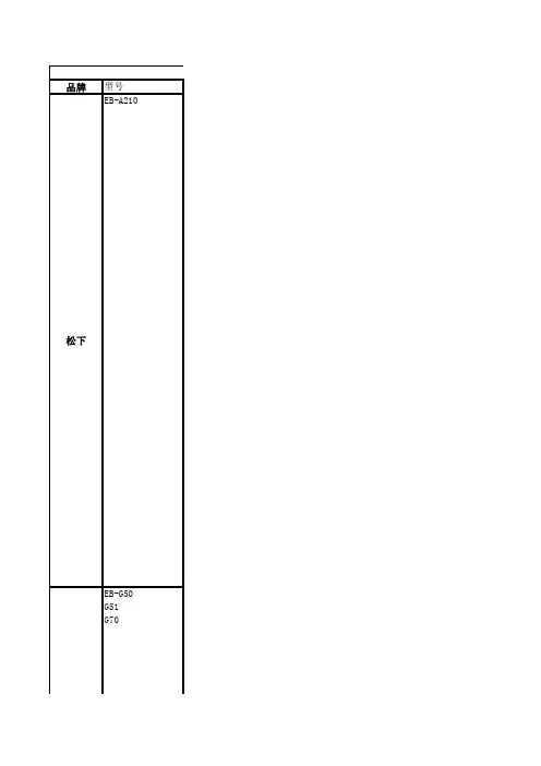
品牌型号EB-A210松下EB-G50G51G70松下EB-G60松下EB-GD55松下EB-GD68松下EB-GD88GD86A 松下EB-X11X88松下EB-X66X77松下EB-X100X500A200松下EB-X300松下EB-X400X200A500松下EB-X700X800松下VS3MX6MX7VS6VS3VS2SA6VS79.选择“浏览器设置”并设置参数如下:主IP地址:010.000.000.172主端口:9201次IP地址:000.000.000.000次端口:9201浏览时间:240主页:http:// 10.选择“GPRS设置”,选择“GPRS开”。
二、浏览WAP网页1.待机屏幕下进入“主菜单”点击“导航键左键”进入“浏览器菜单”;2.选择“打开浏览器”,进入浏览器页面。
一、网络设置1.待机屏幕下进入“主菜单”,点击“导航键上键”进入“浏览器菜单”;2.选择“浏览器设置”;3.选择“WAP”并设置参数如下:激活:服务器名称:WAP拔叫号码:17266呼叫类型:模拟登录名称:WAP密码:WAPIP地址:010.000.000.172IP端口:9201首页网址:浏览时间:300二、浏览WAP网页1.待机屏幕下进入“主菜单”点击“导航键上键”进入“浏览器菜单”;2.选择“打开浏览器”,进入浏览器页面。
一、网络设置1.待机屏幕下进入“主菜单”,点击“导航键左键”进入“浏览器菜单”;2.选择“浏览器设置”;3.选择“服务器设置”;4.选择“移动梦网GPRS”并选择“修改”,设置参数如下:服务器名:移动梦网(GPRS)主页:下载网址:http://端口号:9201网关IP:10.0.0.172服务选择:只用GPRS5.选择“GPRS”后设置如下:接入站点名:CMWAP用户名:置空用户密码:置空鉴权模式:无加密6.在“服务器设置”中选择“移动梦网CSD”并选择“修改”,设置参数如下: 服务器名:移动梦网CSD主页:下载网址:http://端口号:9201网关IP:010.000.000.172服务选择:只用GSM7.选择“GSM”后设置如下:电路类型:模拟数字拔号:17266模拟拔号:17266PPP ID:WAPPPP密码:WAP8.在“服务器设置”中选择“移动梦网(GPRS)”并选择“设定”。
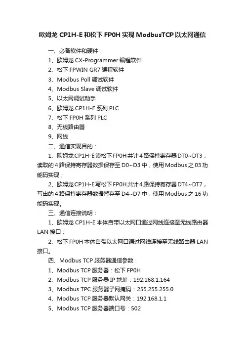
欧姆龙CP1H-E和松下FP0H实现ModbusTCP以太网通信一、必备软件和硬件:1、欧姆龙CX-Programmer编程软件2、松下FPWIN GR7编程软件3、Modbus Poll调试软件4、Modbus Slave调试软件5、以太网调试助手6、欧姆龙CP1H-E系列PLC7、松下FP0H系列PLC8、无线路由器9、网线二、通信实现目的:1、欧姆龙CP1H-E读松下FP0H共计4路保持寄存器DT0~DT3,读取的4路保持寄存器数据保存至D0~D3中,使用Modbus之03功能码实现;2、欧姆龙CP1H-E写松下FP0H共计4路保持寄存器DT4~DT7,写出的4路保持寄存器数据暂存至D4~D7中,使用Modbus之16功能码实现。
三、通信连接说明:1、欧姆龙CP1H-E本体自带以太网口通过网线连接至无线路由器LAN接口;2、松下FP0H本体自带以太网口通过网线连接至无线路由器LAN 接口。
四、Modbus TCP服务器通信参数:1、Modbus TCP服务器:松下FP0H2、Modbus TCP服务器IP地址:192.168.1.1643、Modbus TPC服务器子网掩码:255.255.255.04、Modbus TCP服务器默认网关:192.168.1.15、Modbus TCP服务器端口号:502五、Modbus TCP客户端通信参数:1、Modbus TCP客户端:欧姆龙CP1H-E2、Modbus TCP客户端IP地址:192.168.1.1633、Modbus TPC客户端子网掩码:255.255.255.04、Modbus TCP客户端默认网关:192.168.1.15、Modbus TCP客户端端口号:502六、松下FP0H通信参数设置:1、松下FP0H通信参数设置如下所示:2、松下FP0H设备编号和Modbus寄存器编号、地址对应表如下所示:七、松下FP0H系列PLC逻辑编程:1、初始化时,分别给保持寄存器DT0~DT3赋值0~3,如下所示:2、初始化时,分别对保持寄存器DT4~DT7进行清零,如下所示:3、每1分钟,对DT0~DT3做加1操作,方便客户端读取数据观察变化,如下所示:4、判断DT0~DT3中的数据是否大于6000,如果大于6000,进行清零操作,如下所示:八、使用以太网调试助手测试松下FP0H之Modbus TCP服务器程序:1、Modbus之03功能码测试,读取欧姆龙CP1H-E保持寄存器D0~D3的值:以太网调试助手发送:44 44 00 00 00 06 01 01 00 00 00 04欧姆龙CP1H-E返回:44 44 00 00 00 0B 01 03 08 00 06 00 07 00 08 00 09则此时松下FP0H保持寄存器DT0、DT1、DT2、DT3的数据依次为16#0006、16#0007、16#0008、16#0009,以太网调试助手测试截图如下所示:2、测试总结:以上Modbus之03功能码测试通过,亦表明松下FP0H之Modbus TCP服务器程序正确无误。
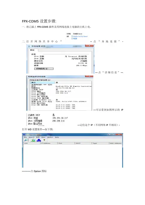
FPX-COM5设置步骤:
一.将已插上FPX-COM5插件及用网线连接上电脑的主机上电。
二.打开网络共享中心“--点“本地连接”-
---点“详细信息”---
---可以看到如图所示的IP
---记住这个IP(不同网络IP不相同)- 打开WD设置软件---如下图:
-----------点Option图标
-----再点“Select the IP of PC”图标—
----再下拉菜单中选择本地连接显示的IP----点OK后----点软件菜单中的---就会读到COM5的信息--
----鼠标光标选择FPX_ET后点菜单中的----出现下图:
----将IP 改成与电脑本地连接同一网段的IP,比如:“上边本地连接显示,169.254.39.217,那就将这个IP改成169.254.39.218”---设置完后点OK---出现下下图:
意思是关掉软件10秒后重
新打开软件!---再点后就会读到COM5设置后的信息。
三.完成以上设置后就可以打开松下GR软件,在“通信设置”中进行如下设置(9094为COM5默认端口)
---设置完成后点OK,然后就可以利用网线下载和监控程序了!
三.改变COM5通信波特率改为115200的方法,默认为9600.
首先将松下编程软件COM1端口的波特率设置为115200,然后打开WD设置软件—
光标选择FPX-ET后点
--再点Communication Setting---会出现:
将9600改为115200 OK----确定!。
以太网功能的操作方法
以太网是一种常用于局域网的网络协议,它的操作方法主要包括以下几个步骤:
1.连接设备:将以太网电缆插入电脑或其他网络设备的以太网接口。
2.设置IP地址:根据需要,可以手动设置设备的IP地址,也可以通过DHCP自动获取。
3.配置本地区域连接:在操作系统中打开网络连接设置,选择以太网连接,然后点击“属性”或“设置”。
4.启用以太网连接:确保以太网连接处于启用状态,这样设备可以进行数据传输。
5.测试连接:打开网页或进行其他网络操作,验证以太网连接是否正常。
6.故障排除:如果以太网连接有问题,可以尝试重新启动设备、检查电缆连接、重置网络设置等方法进行故障排除。
需要注意的是,以太网的操作方法可能会因不同的设备和操作系统而有所不同,以上步骤仅为一般操作流程,具体操作方法请参考设备和操作系统的说明或者进行相关的网络设置。
路由器以太网接入怎么设置
以太网指的是基带局域网规范,是当今现有局域网采用的最通用的通信协议标准,下面是店铺给大家整理的一些有关路由器以太网接入设置方法,希望对大家有帮助!
路由器以太网接入设置方法
1、首先看路由器的背部有一个ip管理地址,然后记下来把。
一般是192.168.1.1
2、用一根网线连接路由器和电脑,电脑修改ip修改如图点击保存。
3、打开网页输入192.168.1.1
4、输入用户名和密码一般的默认用户名和密码是admin 点击登陆进入界面
5、进入界面后会自动弹出设置向导,点击下一步进行设置,如果没有弹出,点击设置向导的导航按钮进行下一步操作。
6、点击下一步进入端口选择一般路由器只有1个端口,我的是企业路由器是4端口的可以拨号4个所以这里我们选择1端口
7、选择好了点击进入下一步进行拨号选择一般有三种大多数都是需要选择第一种部分宽带选择第二种和第三种,
8、点击进入下一步进入拨号帐号和密码输入,点击下一步进行拨号,拨号过程中会出现波不上好,点击重试即可,如果多次拨号拨不上就需要去确认帐号和密码的正确性。
9、点击完成进入系统首页查看是否拨号成功。
出现箭头所指的ip 即表示拨号成功能够正常上网。
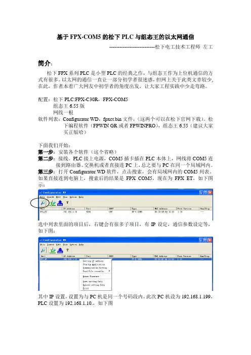
基于FPX-COM5的松下PLC与组态王的以太网通信---------------------------松下电工技术工程师左工简介:松下FPX系列PLC是小型PLC的经典之作,与组态王作为上位机通信的方式有很多。
以太网的通信一直让一部分初学者很迷惑,但网上关于此类文章较少,在此,作者本着广大网友中初学者的角度出发,让大家工程实践中少走弯路。
配置:松下PLC:FPX-C30R,FPX-COM5组态王6.55版网线一根软件列表:Configurator WD,fpxct.bin文件,(这两个可以在松下官网下载)。
松下编程软件(FPWIN GR或者FPWINPRO),组态王6.55(建议大家买正版哈)下面我们开始:第一步:安装各个软件(这个省略)第二步:接线。
PLC接上电源,COM5插卡插在PLC本体上,网线将COM5连接到路由器、交换机或者直接连PC上,总之要与PC在同一个局域网内。
第三步:打开Configurator WD软件,点击搜索,会有局域网内的COM5列表。
如果直接连到电脑上,搜索后的结果是FPX_COM5,现在为FPX_ET,如下图示:选中列表里面的项目后,右键会有很多子项目,有IP设定,通信参数设定等,如下图:其中IP设置,设置为与PC机是同一个号码段内,此次PC机设为192.168.1.199,PLC设置为192.168.1.10.,如下图如果点成上面的自动获取IP,则在WD软件中就不能搜到COM5了,这时就需要把COM5背面有个小的拨码开关拨一下,复位一下,则IP重新变为192.168.1.5.注意里面的参数,波特率可以设置为115200,或者9600.动作模式选择为服务器模式或者客户端模式。
这里选服务器,通信协议可以选为计算机链接或者通用通信。
只要和电脑设置为一样就行。
这里设置为计算机链接。
选中列表后进行服务器连接,再按照下面的步骤进行。
然后选中这个bin文件,点确定,bin文件可以在松下官网下载。
警告:•请勿将本产品置于雨水、潮湿的环境中,以免发生火灾或触电。
•为防止造成伤害等事故,请务必按照安装说明将本产品牢固地固定在地面、墙壁或天花板上。
•安装应当遵照本产品所适用的所有安装规则。
•本产品没有电源开关。
如需切断电源,则关闭电源装置或拔下电源线。
•连接应当符合当地的电气规定。
注意:•标示有本产品机身编号等的标签贴附于本产品的表面。
请在下面空白处填上本产品的机身编号,并将此说明书妥善保存,以便万一遭窃时查核。
型号:SER.No.(机身编号):2目录重要安全须知 (4)有限责任 (5)免责条款 (5)前言 (5)关于标记 (6)特点 (6)关于使用说明书 (7)对电脑的系统要求 (7)商标和注册商标 (8)关于著作权 (8)网络安全 (9)注意事项 (10)安装时的注意事项 (13)各部分的名称 (15)镜头安装 (17)插入和取出SD记忆卡*1 (仅WV-SP509H) (19)安装 (20)连接 (24)使用光盘 (28)配置网络设置 (31)故障排除 (33)规格 (34)附件 (38)选购件 (38)补充说明 (39)*1 SDXC/SDHC/SD记忆卡记载为SD记忆卡。
3不要损坏电源线不要损坏、加工电源线,不要使电源线靠近加热器,不要过分弯折、拧电源线,不要拉扯电源线,不要在电源线上放置很重的东西,不要绑扎电源线。
如果使用有损伤的电源线,可能会导致触电、短路或火灾。
如需修理,请委托经销商。
清洁时请切断电源否则可能导致受伤。
[使用时的注意事项]本产品仅限室内专用。
请勿在室外使用。
本产品没有电源开关切断电源时,需断开直流12 V电源或PoE设备的电源。
(同时使用直流12 V电源和PoE 设备作为电源时,两者均需断开。
)环境要求请勿长时间在高温、高湿的场所使用。
否则有可能会损坏本产品的部件从而缩短使用寿命。
请勿在靠近热源的地方(如加热器附近)使用本产品。
小心轻放本产品避免坠落、强烈冲击或振动,以免损坏产品而造成功能不良。
如何跟松下plc网口通讯近年来,松下PLC(可编程逻辑控制器)在工业自动化领域的应用越来越广泛。
PLC作为控制设备,通过与其他设备的通信实现自动化控制和监控。
其中,与PLC网口通讯是实现数据传输的重要方式之一。
那么,如何与松下PLC的网口进行通讯呢?本文将针对这一问题进行探讨。
首先,要与松下PLC网口进行通讯,我们需要了解PLC网口的工作原理和通讯协议。
PLC网口常用的通讯协议有Modbus TCP、Ethernet/IP等。
在通讯建立之前,首先需要确定PLC的IP地址。
通过PLC的配置软件,可以查看或者设置PLC的IP地址。
确保与PLC连接设备处于同一局域网下,可以通过ping命令来验证连接是否正常。
其次,我们需要借助编程语言或者通讯软件来实现与PLC网口的通讯。
常见的编程语言如C#、Java等,以及专门的通讯软件如Intouch、RSLogix等,都可以实现与PLC网口的通讯。
选择合适的工具主要根据自己的实际需求和编程语言的熟悉程度来确定。
在编程时,首先需要引用相应的通讯库或者API,以便能够正确地与PLC建立通讯连接。
通常,需要提供PLC的IP地址、端口号等连接参数。
通过调用库或者API提供的函数,我们可以实现与PLC的连接、数据的读写和监控等操作。
这些函数通常会返回相应的状态码或者结果值,以便我们判断通讯是否成功或者操作是否完成。
在进行PLC网口通讯时,需要注意一些常见问题和技巧。
首先,要确保PLC与通讯设备之间的IP地址、子网掩码、网关等网络配置正确无误。
其次,要注意PLC网口的通讯速率和数据位数等参数的配置,确保与通讯设备一致。
此外,还需要考虑通讯的稳定性和安全性,可以通过设置超时时间、重连机制、数据加密等方式来提高通讯效率和保障数据的安全传输。
在实际应用中,常常会遇到一些特殊的需求。
例如,需要批量读取或写入PLC的数据,可以通过循环或者多线程的方式提高通讯效率。
又如,需要实时监控PLC的状态和数据变化,可以通过定时查询或者回调函数的方式进行实现。
松下plc网口通讯协议松下PLC网口通信协议随着工业自动化的持续发展,PLC(可编程逻辑控制器)在自动化控制系统中扮演着重要的角色。
作为一种大规模应用的工业控制设备,PLC广泛应用于制造业、能源、交通等各个领域。
而PLC的网口通信协议,对于实现PLC间的互联互通以及与上位机的数据交换至关重要。
本文将就松下PLC的网口通信协议进行一定深度的探讨。
首先,我们来了解松下PLC网口通信协议的背景及重要性。
作为PLC制造商之一,松下电器为自家的PLC产品开发了一系列通信协议,旨在实现PLC与其他设备的高效通信。
这其中,松下PLC网口通信协议被广泛运用于松下PLC产品系列中,使得PLC与上位机、仪器仪表、触摸屏等设备能够实现稳定可靠的通信连接。
松下PLC网口通信协议不仅有助于实现数据的实时采集、监控与控制,还在工业互联网以及工业4.0的应用中具有重要意义。
其次,我们可以进一步探讨松下PLC网口通信协议的技术细节。
松下PLC网口通信协议主要基于以太网技术,通过网口与其他设备进行连接。
常见的松下PLC网口通信协议包括Ethernet/IP、Modbus TCP、FINS等。
Ethernet/IP是一种开放的工业以太网协议,被广泛用于PLC的通信连接。
Modbus TCP则是基于Modbus协议的以太网版本,被许多工业设备所支持。
而FINS(Factory Automation Network Service)则是松下电器自家研发的通信协议,支持PLC与其他松下设备之间的高速通信。
此外,松下PLC网口通信协议的应用范围也值得一提。
随着工业自动化的快速发展,PLC在许多行业中广泛应用。
例如,在制造业中,松下PLC网口通信协议可以实现生产线各个PLC节点之间的数据传输与协调,从而提高生产效率和质量。
在能源行业,PLC网口通信协议可以实现电力系统的远程监控与控制,确保电网的稳定运行。
此外,松下PLC网口通信协议还可在交通、电力、化工等领域有着广泛的应用。
D P-8020P所提供的打印能力并节约成本。
DP-8020E/DP-8020P可利用标配的USB接口与单独的个人电脑进行连接。
综上所述,DP-8020E/ DP-8020P具备多种友好的商业功能,例如:海报模式和N合一的打印模式。
通过状态监视器用户不必离开自己的座位就可以对WORKiO DP-8020E/8020P当前状态进行监控。
状态监视器
PCL 打印*2postscript打印*3
*2需要选购打印机控制器模块*3需要选购多页面描述
语言控制模块
原稿扫描区域原稿扫描区域
在键盘选购件上可以设置多达32个的传真号码,电子邮件地址和PC机地址,便于进行单键发送。
此外,您还可以在扫描或发送电子邮件之前,利用标准传统键盘为您的文件命名。
欢迎来到WORKiO数码图像世界,在这里数字通信系统和图像技术将融会贯通WORKiO不仅能使您的商业拥有更多功能,更高的安全性,而且使您的操作更加简单,并具备更广的
扫描至电脑)
)
DA-AR202(适用于DP-8020E。
使用说明书 通信接口装置型号:Panasonic 产品。
●请仔细阅读使用说明书以确保正确安全的使用。
●使用前请务必阅读“安全注意事项”或者“安全手册”。
●请确认保修卡的“购买日期、验收日期及销售代理店名称”等信息无误后,和说明书一起妥善保管。
●产品序列号:TSMYU966,TSMYU968。
TSM50793-04TSMYU966TSMYU968◆适用对象:本通信接口装置需要配套FT2系列(焊接电源具体型号请与代理商联系)使用,可实现与他社机器人等控制装置连接, 同时可实现焊接电源与Panasonic智能焊接云管理系统的连接。
◆免责声明:符合下述任何一种情况时,本公司及本产品的销售商将不承担责任:1、未实施正常的保养、维修以及定期检查而造成的损坏;2、自然灾害或其他不可抗力造成的损坏;3、本公司产品以外的产品、部件不良引发的本公司产品不良,或者将本公司产品和本公司以外的产品、部件、电路、软件等组合使用而引发的问题;4、误操作、异常运转、其他非本公司责任引发的不良;5、由于使用本产品(包含使用本产品制造出的产品为对象的纷争)而引发的知识产权问题(工艺、方法等专利问题);6、由于本产品的原因而造成的利益损失、工时损失等损害或者其他间接损害、派生损害等。
◆松下智能焊接设备功能声明:1、松下智能焊接设备已安装物联网SIM卡,已与唐山松下产业机器有限公司的智能焊接云管理系统(iWeld云平台)实现连接。
用户初次使用本产品,需在智能焊接云管理系统端进行确认。
2、本产品可收集的设备信息包括:●本产品地理方位,通过GPS或者移动基站定位取得;●预置电流、预置电压、焊接电流、焊接电压、焊接速度、示教程序名称、送丝速度、报警代码、焊接时间、焊接设定条件(气体、材质、丝径、收弧有无、脉冲有无等)等数据;以及设备班组、作业者、焊接工艺规范(电流电压范围)、工件编号等用户自主录入的数据。
3、设备信息的使用●向需方提供焊接设备精准服务。
以太网连接和设置方法随着科技的不断发展,互联网已经成为了我们生活中不可或缺的一部分。
而以太网作为最常用的有线网络连接方式,也在我们的生活中扮演着重要的角色。
本文将为大家介绍以太网连接和设置的方法,帮助大家更好地使用以太网。
一、连接以太网连接以太网的方法有两种,一种是通过有线连接,另一种是通过无线连接。
首先我们来介绍有线连接的方法。
1. 选择合适的以太网线在连接以太网之前,我们首先需要选择一根合适的以太网线。
以太网线有不同的规格和类型,常见的有CAT5、CAT5e和CAT6等。
根据自己的需求和网络环境选择合适的以太网线。
2. 连接以太网线将一端插入电脑或者路由器的以太网口,将另一端插入宽带猫或者网络交换机的以太网口。
确保插入牢固,连接稳定。
接下来,我们来介绍无线连接的方法。
1. 打开电脑或者手机的无线网络设置在电脑或者手机的设置中找到无线网络设置,点击打开。
一般情况下,我们可以在任务栏或者设置菜单中找到无线网络设置选项。
2. 搜索可用的无线网络在无线网络设置界面中,点击搜索可用的无线网络。
系统会自动扫描附近的无线网络,并将搜索结果显示在界面上。
3. 选择并连接无线网络根据搜索结果,选择要连接的无线网络,并输入密码(如果有的话)。
点击连接按钮,等待连接成功。
二、设置以太网连接以太网之后,我们还需要进行一些设置,以确保网络的稳定和安全。
1. IP地址设置在Windows系统中,我们可以通过以下步骤设置IP地址:依次点击“开始”、“控制面板”、“网络和Internet”、“网络和共享中心”、“更改适配器设置”。
在适配器设置界面中,找到以太网适配器,右键点击并选择“属性”。
在属性窗口中,找到“Internet协议版本4(TCP/IPv4)”,点击“属性”。
在弹出的窗口中,选择“使用下面的IP地址”,填写IP地址、子网掩码和默认网关等信息。
2. DNS服务器设置在Windows系统中,我们可以通过以下步骤设置DNS服务器:在上述的属性窗口中,点击“高级”按钮,在“DNS”选项卡中,点击“添加”按钮,输入首选DNS 服务器和备用DNS服务器的IP地址。
网口与松下plc通讯网络口(Ethernet)是一种常见的计算机网络连接接口,可用于实现不同设备之间的数据传输和通信。
而松下PLC (Programmable Logic Controller)是一种广泛应用于工业自动化领域的计算机控制系统。
本文将探讨网络口和松下PLC之间的通讯方式以及相关应用。
一、网络口与松下PLC通讯的背景与重要性在现代工业自动化领域,PLC作为一种可编程逻辑控制器,已经被广泛应用于各种各样的生产自动化系统中。
网络通讯的出现和发展,为PLC与其他设备之间的数据传输和信息交换提供了新的方式和可能性。
而网络口作为实现网络通讯的接口,正逐渐成为PLC与其他设备之间通讯的首选方案。
因此,深入了解网络口与松下PLC通讯的方式和应用对于工业自动化技术与发展具有重要意义。
二、网络口与松下PLC通讯的基本原理1. 以太网通讯方式:网络通讯方式有多种,而以太网是其中一种常用的方式。
以太网使用网络电缆连接设备,通过数据包的方式进行数据传输和通信。
以太网通讯方式的优势在于其高速、稳定和可靠的特点。
2. 松下PLC通讯方式:松下PLC通讯方式基于PLC的通讯协议和数据格式。
通常,为了实现PLC与网络口之间的通讯,需要使用特定的PLC通讯模块或者PLC编程软件来配置和设置网络参数,包括IP地址、子网掩码、网关等。
三、网络口与松下PLC通讯的应用案例1. 数据采集与监控:通过网络口与松下PLC的通讯,可以实现对生产设备的数据采集和监控。
通过采集数据,可以实时了解设备状态,以便及时发现和解决问题,提高生产效率和质量。
2. 远程控制与管理:利用网络口与松下PLC通讯的特性,可以实现对远程设备的控制和管理。
例如,在生产线上,通过远程连接PLC,可以实现对设备的开启、关闭、启动等操作。
这种远程控制的方式不仅方便,还提高了工作效率和灵活性。
3. 数据传输与集成:在工业自动化系统中,常常需要将不同设备之间的数据进行传输和集成。
FPX-COM5设置步骤:
一.将已插上FPX-COM5插件及用网线连接上电脑的主机上电。
二.打开网络共享中心“--点“本地连接”-
---点“详细信息”---
---可以看到如图所示的IP
---记住这个IP(不同网络IP不相同)- 打开WD设置软件---如下图:
-----------点Option图标
-----再点“Select the IP of PC”图标—
----再下拉菜单中选择本地连接显示的IP----点OK后----点软件菜单中的---就会读到COM5的信息--
----鼠标光标选择FPX_ET后点菜单中的----出现下图:
----将IP 改成与电脑本地连接同一网段的IP,比如:“上边本地连接显示,169.254.39.217,那就将这个IP改成169.254.39.218”---设置完后点OK---出现下下图:
意思是关掉软件10秒后重
新打开软件!---再点后就会读到COM5设置后的信息。
三.完成以上设置后就可以打开松下GR软件,在“通信设置”中进行如下设置(9094为COM5默认端口)
---设置完成后点OK,然后就可以利用网线下载和监控程序了!
三.改变COM5通信波特率改为115200的方法,默认为9600.
首先将松下编程软件COM1端口的波特率设置为115200,然后打开WD设置软件—
光标选择FPX-ET后点
--再点Communication Setting---会出现:
将9600改为115200 OK----确定!。