Zigbee协议的API接口函数手册
- 格式:pdf
- 大小:418.01 KB
- 文档页数:65
IO操作函数函数原型:IORD(BASE, REGNUM)输入参数:BASE为寄存器的基地址,REGNUM为寄存器的偏移量函数说明:从基地址为BASE的设备中读取寄存器中偏移量为REGNUM的单元里面的值。
寄存器的值在地址总线的范围之内。
返回值:-函数原型:IOWR(BASE, REGNUM, DATA)输入参数:BASE为寄存器的基地址,REGNUM为寄存器的偏移量,DATA为要写入的数据函数说明:往偏移量为REGNUM寄存器中写入数据。
寄存器的值在地址总线的范围之内。
返回值:-函数原型:IORD_32DIRECT(BASE, OFFSET)输入参数:BASE为寄存器的基地址,OFFSET为寄存器的的偏移量函数说明:从地址位置为BASE+OFFSET的寄存器中直接读取32Bit的数据返回值:-函数原型:IORD_16DIRECT(BASE, OFFSET)输入参数:BASE为寄存器的基地址,OFFSET为寄存器的的偏移量函数说明:从地址位置为BASE+OFFSET的寄存器中直接读取16Bit的数据返回值:-函数原型:IORD_8DIRECT(BASE, OFFSET)输入参数:BASE为寄存器的基地址,OFFSET为寄存器的的偏移量函数说明:从地址位置为BASE+OFFSET的寄存器中直接读取8Bit的数据返回值:-函数原型:IOWR_32DIRECT(BASE, OFFSET, DATA)输入参数:BASE为寄存器的基地址,REGNUM为寄存器的偏移量,DATA为要写入的数据函数说明:往地址位置为BASE+OFFSET的寄存器中直接写入32Bit的数据返回值:-函数原型:IOWR_16DIRECT(BASE, OFFSET, DATA)输入参数:BASE为寄存器的基地址,REGNUM为寄存器的偏移量,DATA为要写入的数据函数说明:往地址位置为BASE+OFFSET的寄存器中直接写入16Bit的数据返回值:-函数原型:IOWR_8DIRECT(BASE, OFFSET, DATA)输入参数:BASE为寄存器的基地址,REGNUM为寄存器的偏移量,DATA为要写入的数据函数说明:往地址位置为BASE+OFFSET的寄存器中直接写入8Bit的数据返回值:-Dma:函数原型:int alt_dma_rxchan_close (alt_dma_rxchan rxchan)输入参数:rxchan为接收信道函数说明:函数 alt_dma_rxchan_close ()通知系统:应用程序已经完成DMA 接收信道rxchan,目前执行是成功的返回值:成功返回为0,反之为-1函数原型:alt_dma_rxchan_depth(alt_dma_rxchan dma)输入参数:dma函数说明:函数alt_dma_rxchan_depth ()返回传送到特别DMA的最大数量(深度)的接收请求返回值: DMA的最大数量函数原型:int alt_dma_rxchan_ioctl (alt_dma_rxchan dma, int req, void* arg)输入参数:dma直接存储器名, req为请求操作的列举, arg由请求决定函数说明:通过DMA接收信道执行设备的具体I/O操作返回值:成功返回请求具体值,反之返回为负数请求类型请求类型请求类型说明ALT_DMA_SET_MODE_8 传输以8Bit为单位的数据,arg值忽略ALT_DMA_SET_MODE_16 传输以16Bit为单位的数据,arg值忽略ALT_DMA_SET_MODE_32 传输以32Bit为单位的数据,arg值忽略ALT_DMA_SET_MODE_64 传输以64Bit为单位的数据,arg值忽略ALT_DMA_SET_MODE_128 传输以128Bit为单位的数据,arg值忽略ALT_DMA_TX_ONLY_ON (1) 软件控制下只能发送ALT_DMA_TX_ONLY_OFF (1) 自定义模式,软件控制下可以接收,发送ALT_DMA_RX_ONLY_ON (1) 软件控制下只能接收ALT_DMA_RX_ONLY_OFF (1) 自定义模式,软件控制下可以接收,发送函数原型:alt_dma_rxchan alt_dma_rxchan_open (const char* name)输入参数:name为常数字符指针,如/dev/dma_0函数说明:为DMA接收信道获得一个alt_dma_rxchan描述符返回值:成功返回非0,反之返回为0函数原型:int alt_dma_rxchan_prepare (alt_dma_rxchan dma, void* data, alt_u32 length, alt_rxchan_done * done, void* handle)输入参数:dma使用的信道;data接收数据位置的指针;length最大的接收数据长度;done一旦数据被接收,调用返回函数;handle,非透明值传到done 函数说明:发送一个接收请求到DMA接收信道,返回值:成功返回0,反之返回为负数函数原型:int alt_dma_rxchan_reg (alt_dma_rxchan_dev * dev)输入参数:dev接收信道设备名函数说明:给系统寄存DMA接收信道返回值:成功返回0,反之返回为负数函数原型:int alt_dma_txchan_close (alt_dma_txchan txchan)输入参数:txchan发送信道名函数说明:通知系统:应用程序已经完成DMA发送信道txchan返回值:成功返回0,反之返回为负数函数原型:int alt_dma_txchan_ioctl (alt_dma_txchan dma, int req, void* arg)输入参数:dma直接存储器名;req为请求操作的列举;arg请求的额外参数,由请求决定函数说明:通过DMA发送信道执行设备的具体I/O操作返回值:成功返回请求具体值,反之返回为负数函数原型:alt_dma_txchan alt_dma_txchan_open (const char* name)输入参数:name为常数字符指针,如/dev/dma_0函数说明:为DMA发送信道获得一个alt_dma_rxchan描述符返回值:成功返回非0,反之返回为0函数原型:int alt_dma_txchan_reg (alt_dma_txchan_dev* dev)输入参数:dev接收信道设备名函数说明:给系统寄存DMA发送信道返回值:成功返回0,反之返回为负数函数原型:int alt_dma_txchan_send (alt_dma_txchan dma, const void* from, alt_u32 length, alt_txchan_done* done, void* handle)输入参数:dma使用的信道;data接收数据位置的指针;length最大的接收数据长度;done一旦数据被接收,调用返回函数;handle,非透明值传到done函数说明:发送一个发送请求到DMA发送信道,返回值:发送成功返回0,反之返回为负数函数原型:nt alt_dma_txchan_space (alt_dma_txchan dma)输入参数:dma 直接存储器名函数说明:返回被传送到具体DMA发送信道的发送请求数目返回值:返回发送请求数目Flash函数原型:int alt_erase_flash_block(alt_flash_fd* fd, int offset, int length)输入参数:fd为具体的flash设备;offset擦除的flash模块的偏移量;length 擦除的flash模块的长度函数说明:擦除单独的一个flash模块返回值:发送成功返回0,反之返回为负数函数原型:void alt_flash_close_dev(alt_flash_fd * fd)输入参数:fd为具体的flash设备函数说明:关闭flash设备返回值:-函数原型:alt_flash_fd * alt_flash_open_dev(const char* name)输入参数:函数说明:打开flash设备。
#1楼主:【原创】ZigBee学习之13——ZStack API解读文章发表于:2010-02-06 15:48Z-Stack API[Z-Stack API _F8W-2006-0021_.pdf]这个文档是一个关键了,Z-Stack的应用程序接口。
我们在程序中基本上应该调用的是这些API吧。
ZDO层API实现了所有ZDP(ZigBee Device Profile)定义的命令和回应所需要的函数。
ZDP描述了ZDO 如何实现普通ZigBee设备的特性,它定义了设备描述和簇,ZDP为ZDO和应用提供一下功能:·设备网络建立·设备和服务发现·节点设备邦定和解邦定服务·网络管理服务设备发现是ZigBee设备发现其他ZigBee设备的过程。
比如将已知的IEEE地址作为数据载荷广播到网络的NWK地址请求,相关设备必须回应并告知其网络地址。
服务发现提供了PAN中一个设备发现其他设备提供的服务的能力。
它利用多种描述符去指定设备的能力。
当用户需要邦定控制器与被控设备(比如开关和灯)时,将用到邦定和解邦定服务。
特别是终端设备邦定支持利用用户的输入来定义控制/被控设备对的简单邦定方法。
邦定和解邦服务可以创建和删除邦定表入口。
网络管理服务主要提供给用户和调试工具网络管理的能力,它能够从设备重新获得管理信息,包括网络发现结果,路由表的内容,邻居节点链路质量,邦定表内容。
也可以通过解关联将设备从PAN中脱离来控制网络关联。
ZDO设备网络建立在ZigBee网络中默认ZDApp_Init()[in ZDApp.c]开始器件的启动,但是应用能覆盖整个默认行为,为了使应用接管网络的启动,必须在编译选项中包含HOLD_AUTO_START,推荐同时包含NV_RESTORE(储存ZigBee网络状态到NV)编译选项,包含这个两个编译选项后就需要调用ZDOInitDevice() 来启动网络中的设备。
ZigBee学习之16——ZStack API解读4应用支持子层(APS)应用支持子层提供如下管理功能:∙邦定表管理∙组表管理∙快速地址查找除了管理功能外,APS还提供数据服务,只是应用不能访问数据服务。
应用需要通过AF数据接口AF_DataRequest()来发送数据。
如果要使用邦定表函数需要包含BindingTable.h头文件。
邦定表管理请注意,绑定服务只能在“互补”设备之间建立。
那就是,只有分别在两个节点的简单描述结构体(simple descriptor structure)中,同时注册了相同的命令标识符(command_id)并且方向相反(一个属于输出指令“output”,另一个属于输入指令“input”),才能成功建立绑定。
APS邦定表是在静态RAM中定义的一张表,定义在nwk_globals.c中。
表的大小可以通过f8wCo nfig.cfg中的[NWK_MAX_BINDING_ENTRIES和MAX_BINDING_CLUSTER_IDS]莱配置。
只有定义了R EFLECTOR或者COORDINATOR_BINDING才能包含此表,用REFLECTOR编译选项来支持APS层的源邦定。
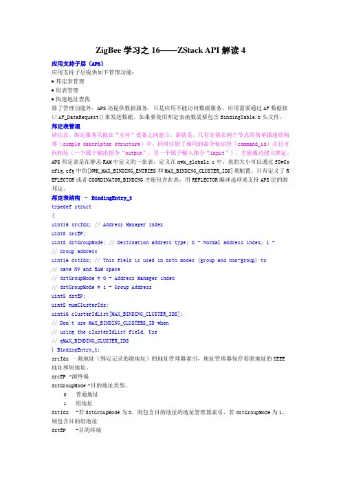
邦定表结构– BindingEntry_ttypedef struct{uint16 srcIdx; // Address Manager indexuint8 srcEP;uint8 dstGroupMode; // Destination address type; 0 - Normal address index, 1 -// Group addressuint16 dstIdx; // This field is used in both modes (group and non-group) to// save NV and RAM space// dstGroupMode = 0 - Address Manager index// dstGroupMode = 1 - Group Addressuint8 dstEP;uint8 numClusterIds;uint16 clusterIdList[MAX_BINDING_CLUSTER_IDS];// Don't use MAX_BINDING_CLUSTERS_ID when// using the clusterIdList field. Use// gMAX_BINDING_CLUSTER_IDS} BindingEntry_t;srcIdx –源地址(绑定记录的源地址)的地址管理器索引,地址管理器保存着源地址的IEEE地址和短地址。
zigbee,协议栈,按键事件篇一:从Zigbee协议栈底层添加自己的按键配置本实验是基于ZStack-CC2530-2.5.1a版本的协议栈来进行实验的,整个实验需要改动hal_board_cfg.h、hal_board_cfg.h、hal_key.c、hal_key.h和自己定义的Coordinator.c这5个文件。
注意:添加自己的按键时尽量不要修改协议栈里面的按键程序,自己另行添加即可。
1、hal_key.h在/* Switches (keys) */下面添加自己的按键定义#define HAL_KEY_SW_8 0x80图1:----------------------------------------------------------------------------------------2、hal_board_cfg.h(转载于: 小龙文档网:zigbee,协议栈,按键事件) 在/* S6 */#define PUSH1_BV BV(1)#define PUSH1_SBIT P0_1#if defined (HAL_BOARD_CC2530EB_REV17)#define PUSH1_POLARITY ACTIVE_LOW#elif defined (HAL_BOARD_CC2530EB_REV13)#define PUSH1_POLARITY ACTIVE_LOW#else#error Unknown Board Indentifier#endif下面模仿/* S6 */下的程序定义自己的按键值:/* S8 */#define PUSH8_BVBV(4)//修改#define PUSH8_SBIT P0_4//修改#if defined (HAL_BOARD_CC2530EB_REV17)#define PUSH8_POLARITY ACTIVE_HIGH#elif defined (HAL_BOARD_CC2530EB_REV13)#define PUSH8_POLARITY ACTIVE_LOW#else#error Unknown Board Indentifier#endif图2:------------------------------------------------------------------------------------------------------------- 在/* ----------- Push Buttons ---------- */#define HAL_PUSH_BUTTON1() (PUSH1_POLARITY (PUSH1_SBIT)) #define HAL_PUSH_BUTTON2() (PUSH2_POLARITY (PUSH2_SBIT)) #define HAL_PUSH_BUTTON3() (0)#define HAL_PUSH_BUTTON4() (0)#define HAL_PUSH_BUTTON5() (0)#define HAL_PUSH_BUTTON6() (0)下定义自己的按键函数#define HAL_PUSH_BUTTON8() (PUSH8_POLARITY (PUSH8_SBIT)) 图3:---------------------------------------------------------------------------------------------------------------- hal_key.c在/* SW_6 is at P0.1 */#define HAL_KEY_SW_6_PORTP0#define HAL_KEY_SW_6_BIT BV(1)#define HAL_KEY_SW_6_SEL P0SEL#define HAL_KEY_SW_6_DIR P0DIR/* edge interrupt */#define HAL_KEY_SW_6_EDGEBIT BV(0)#define HAL_KEY_SW_6_EDGEHAL_KEY_FALLING_EDGE/* SW_6 interrupts */#define HAL_KEY_SW_6_IENIEN1 /* CPU interrupt mask register */#define HAL_KEY_SW_6_IENBITBV(5) /* Mask bit for all of Port_0 */#define HAL_KEY_SW_6_ICTL P0IEN /* Port Interrupt Control register */ #define HAL_KEY_SW_6_ICTLBIT BV(1) /* P0IEN - P0.1 enable/disable bit */ #define HAL_KEY_SW_6_PXIFG P0IFG /* Interrupt flag at source */下模仿/* SW_6 is at P0.1 */建立自己的按键函数#define HAL_KEY_SW_8_PORTP0#define HAL_KEY_SW_8_BIT BV(4) //修改#define HAL_KEY_SW_8_SEL P0SEL#define HAL_KEY_SW_8_DIR P0DIR/* edge interrupt */#define HAL_KEY_SW_8_EDGEBIT BV(0)#define HAL_KEY_SW_8_EDGE HAL_KEY_FALLING_EDGE/* SW_8 interrupts */#define HAL_KEY_SW_8_IENIEN1 /* CPU interruptmask register */#define HAL_KEY_SW_8_IENBITBV(5) /* Mask bit for all of Port_0 */#define HAL_KEY_SW_8_ICTL P0IEN /* Port Interrupt Control register */ #define HAL_KEY_SW_8_ICTLBIT BV(4)//修改#define HAL_KEY_SW_8_PXIFG P0IFG /* Interrupt flag at source */图4:------------------------------------------------------------------------------------------------------------- 注意:将void HalKeyPoll (void)中的// if ((HAL_KEY_JOY_MOVE_PORT & HAL_KEY_JOY_MOVE_BIT)) /* Key is active HIGH */ // {// keys = halGetJoyKeyInput();// }/* If interrupts are not enabled, previous key status and current key status* are compared to find out if a key has changed status.*/// if (!Hal_KeyIntEnable)// {// if (keys == halKeySavedKeys)// {/* Exit - since no keys have changed *///return;// }/* Store the current keys for comparation next time */// halKeySavedKeys = keys;// }// else// {/* Key interrupt handled here */// }图5:全部注释掉,因为它会对我们设定的按键产生干扰,具体情况我也不知道... 然后再在内模仿:if (HAL_PUSH_BUTTON1()){keys |= HAL_KEY_SW_6;}篇二:ZigBee系统事件ZIGBEE事件ZIGBEE事件有两类,系统定义事件和用户定义事件。
网络层(NWK)网络层为高层提供下面函数功能:∙网络管理∙地址管理∙网络变量和效能函数除了管理功能外,NWK还提供数据服务,只是应用不能访问数据服务。
应用需要通过AF数据接口AF_DataRequest()来发送数据。
网络管理ZStatus_t NLME_NetworkDiscoveryRequest( uint32 ScanChannels,byte ScanDuration );用来请求网络层发现邻居路由器。
在加入操作执行网络扫描前应该调用此函数。
扫描确认(结果)将以回调函数ZDO_NetworkDiscoveryConfirmCB()返回。
推荐用户使用ZDO_StartDevice()来代替此函数。
(除非你清楚的知道网络加入过程)ScanChannels -执行发现的通道,2.4GHz条件下只能使用通道11-26(0x07FFF800)ScanDuration -新网络启动前,每个通道被其他网络扫描的时间BEACON_ORDER_15_MSEC 0 15.36 millisecondsBEACON_ORDER_30_MSEC 1 30.72 millisecondsBEACON_ORDER_60_MSEC 2 61.44 millisecondsBEACON_ORDER_120_MSEC 3 122.88 millisecondsBEACON_ORDER_240_MSEC 4 245.76 millisecondsBEACON_ORDER_480_MSEC 5 491.52 millisecondsBEACON_ORDER_1_SECOND 6 983.04 millisecondsBEACON_ORDER_2_SECONDS 7 1966.08 millisecondsBEACON_ORDER_4_SECONDS 8 3932.16 millisecondsBEACON_ORDER_7_5_SECONDS 9 7864.32 milliseconds BEACON_ORDER_15_SECONDS 10 15728.64 milliseconds BEACON_ORDER_31_SECONDS 11 31457.28 milliseconds BEACON_ORDER_1_MINUTE 12 62914.58 millisecondsBEACON_ORDER_2_MINUTES 13 125829.12 milliseconds BEACON_ORDER_4_MINUTES 14 251658.24 milliseconds BEACON_ORDER_NO_BEACONS 15 No Beacons transmitted 返回值:ZStatus_t -ZComDef.h中定义的状态值ZStatus_t NLME_NwkDiscReq2( NLME_ScanFields_t* fields );用来请求网络层发现邻居路由器。
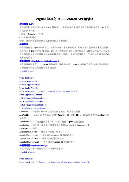
ZigBee 学习之1515——————ZStackZStack API 解读3应用框架(AF)应用框架层是应用道APS 层的OTA 数据接口。
此层也接收数据消息的终端多路复用器。
AF 为应用提供以下功能:•终端(Endpoint)管理•发送和接收数据哈哈,这里的函数应该就是我们经常要用到的函数了。
终端管理每个设备都是Zigbee 中的节点,每个节点有长地址和短地址,短地址被其他设备用来发送数据。
每个节点又241个终端(0保留,1-240可分配给应用)。
每个终端可以独立设置地址;当设备发送数据时必须指定目标设备的短地址和接收终端。
一个应用必须注册一个或多个终端用来接收或者发送数据。
简单描述符-SimpleDescriptionFormat_t每个终端都必须有一个Zigbee 简单描述。
这些描述对Zigbee 网络刻画了这个终端,其他设备可以询问这个终端以知道这个设备的类型。
typedef struct{byte EndPoint;uint16AppProfId;uint16AppDeviceId;byte AppDevVer:4;byte Reserved:4;//AF_V1_SUPPORT uses for AppFlags:4.byte AppNumInClusters;cId_t *pAppInClusterList;byte AppNumOutClusters;cId_t *pAppOutClusterList;}SimpleDescriptionFormat_t;EndPoint –终端号:1-240这是节点的子地址,用来接收数据AppProfId –定义了这个终端上支持的Profile ID(剖面ID),ID 最好遵循由ZigBee 联盟的分配。
AppDeviceId –终端支持的设备ID,ID 最好遵循ZigBee 联盟的分配。
AppDevVer –此终端上设备执行的设备描述的版本:0x00为Version 1.0.Reserved –保留AppNumInClusters –终端支持的输入簇数目pAppInClusterList –指向输入Cluster ID 列表的指针AppNumOutClusters –终端支持的输出簇数目pAppOutClusterList –指向输出Cluster ID 列表的指针终端描述符-endPointDesc_t节点中的每一个终端都必须有一个终端描述符typedef struct{byte endPoint;byte *task_id;//Pointer to location of the Application task ID.SimpleDescriptionFormat_t*simpleDesc;afNetworkLatencyReq_t latencyReq;}endPointDesc_t;task_id-任务ID指针,当接收到消息时,此任务ID将指示消息传递目的。

Zigbee协议栈的使用流程1. 什么是Zigbee协议栈Zigbee协议栈是一种基于IEEE 802.15.4标准的低功耗、自组织的无线通信协议。
它被广泛应用于物联网设备、智能家居、工业自动化等领域。
Zigbee协议栈提供了一套完整的网络协议和通信机制,方便开发者在无线传感器网络中进行通信和数据交换。
2. Zigbee协议栈的使用流程Zigbee协议栈的使用流程可以分为以下几个步骤:步骤一:选择Zigbee协议栈在开始使用Zigbee协议栈之前,首先需要选择合适的Zigbee协议栈。
目前市面上有许多不同的Zigbee协议栈提供商,可以根据自己的需求选择适合的协议栈。
步骤二:准备开发环境在开始使用Zigbee协议栈之前,需要准备好相应的开发环境。
这包括硬件设备、开发工具以及相应的驱动程序。
一般来说,开发者需要购买Zigbee芯片和开发板,并安装相应的开发工具和驱动程序。
步骤三:编写应用程序一旦准备好开发环境,就可以开始编写Zigbee应用程序了。
首先,需要了解Zigbee协议栈的API和接口,理解Zigbee网络的特点和通信机制。
然后,根据具体需求,设计和实现相应的功能模块,例如网络配置、数据传输和安全性等。
步骤四:测试和调试编写完应用程序后,需要进行测试和调试,以确保程序的正确性和稳定性。
可以通过模拟器或者实际的Zigbee设备进行测试。
测试过程中需要注意检查网络连接、数据传输和异常情况处理等方面的功能。
步骤五:部署和运行在完成测试和调试后,就可以将应用程序部署到真实的Zigbee设备上了。
根据具体的部署场景,可能需要进行设备安装、网络配置和数据监控等工作。
一旦部署完成,就可以正式运行Zigbee协议栈,并进行数据交换和通信了。
3. 使用Zigbee协议栈的注意事项在使用Zigbee协议栈的过程中,需要注意以下几个方面:•理解Zigbee网络的拓扑结构和层次关系,合理设计网络拓扑和路由规划。
•注意设备之间的信号强度和信号干扰的问题,确保通信质量和稳定性。
从零开始学习Zstack之1magicchip 发表于2008-9-3 10:37:00首先介绍下本人技术背景:我是一名正宗的销售人员,虽然之前搞过几天技术,但是早就忘到老远了。
不过还是有点单片机和C 语言的基础,而且对ZigBee已经有初步了解。
怎么也弄过几天,加上本人天资聪颖,几天顶一般人几年,所以…………….,一句话:本人技术背景很复杂!再来说下写这些的目的:1、作为一名销售员,而且是针对技术性的产品的销售,我接触的99.99999……%都是技术人员,即使偶尔解除采购的,也是技术人员选好型让他购买的。
所以不怎么懂技术的我,在销售中真是困难重重,为了更好的支撑我的销售,所以决定学习下技术。
2、边学习边做笔记是我一向的坏习惯,但是以前用的都是圆珠笔,现在不是都提倡无纸办公的嘛,所以本人已经N久没有买过本子了,笔就只有办公室里有(因为平时销售也得做记录的)。
加上我遇到很多初学的客户拿到系统之后也是一头雾水,所以一开始学这个我就打算做好详细的记录,以便与前辈们交流共享。
3、那就是网上很流传某某笔记的嘛,呵呵!我也想出过小名!4、就是在家闲着也是闲着,不如做点稍稍有意义的事5、本人最近弄了个网站,还请同行多多关照。
上面的内容太空洞,想到网站上搜索点文章放上去吧,又觉得有悖初衷,不如自己写点东西放上去,反正是我的网站我做主嘛,即使错了也不至于向别的论坛上遭到群愤,我的地方哪个敢??哈哈!!6、………………………….废话是不是太多了!没办法,搞销售的就这样,交际第一条就是废话嘛!Zstack情况:本人采用的是TI的Zstack1.4.3协议,据说这个需要IAR7.30B及以上版本,而目前市面上又没有破解,所以用的人很少,这也是我的机会!呵呵!(傻笑有点多,关键是WORD里没有表情符号,不能正常表达我此时的心情!)正式开始:开始之前在说一句:从TI网站上下载的Zstack的方法就不介绍了。
否则就是从-1开始了而不是从0开始了-----------------我是这么觉得的!第一步:安装Zstack从TI官方网站上下载的Zstack为:swrc072c.zip,我想这个压缩包大家都认识。

ZigBee模块产品数据手册广州星博信息技术有限公司Guangzhou Great Symbol Information Technology Co.,Ltd一、概述ZigBeee模块分为基本型和增强,增强型/基本型模块开放了许多外设端口,两个模块的引脚完全兼容,可以通过SDK对模块进行配置后,使用其相应的外设端口,实现数据的采集、外部设备的控制等,其上面有一个天线接口,用于外接天线。
增强型模块和基本型模块开放的外设端口有:基本型模组(1)1个串行通信接口(UART)(2)4个模拟量输入通道(ADC)(3)14个含复用的通用数字输入输出口(GPIO),不复用ADC/UART时最大为8个(复用:不使用UART/ADC功能时,所有IO可配置成GPIO)●增强型模组(1)42个含复用的通用数字输入输出口(GPIO),不复用ADC /DAC/ UART/ SPI/I2C/ CAN功能引脚时最大为9个(2)3个串行外设接口(SPI),其中1个复用ADC(3)2个内部集成总线接口(I2C),其中1个复用UART(4)1个工业现场总线接口(CAN)(5)4个串行通信接口(UART),其中1个复用I2C(6)12个模拟量输入通道(ADC),其中2个复用DAC,3个复用SPI(7)2个模拟量输出通道(DAC)(8)8个16位同步定时器二、产品特性●基本型模组◆尺寸:PCB贴片封装38.6*23.2*3mm◆重量:约3g◆电源:2V-3.6V 典型值:3.3V◆模块总功耗:A无线模块不工作时平均功耗12-13.5mWB无线模块工作时平均功耗97-121mWC无线模块工作时峰值功耗105-138mW◆天线功率:4dBm◆接收灵敏度:-97dBm◆电流:工作电流小于45mA ,待机电流小于1mA◆工作频率: 2.4G ISM频段◆环境温度:-20~75℃◆无线传输距离:200-250m(外接5dB鞭状天线),300-400m(外接9dB鞭状天线) 注:无线传输的距离测试时环境为:内部增益设定为4dB,空旷的环境下测出的直线距离,中间没有障碍物。
ZigBee学习之14——ZStack API解读2ZDO邦定API绑定机制允许一个应用服务在不知道目标地址的情况下向对方(的应用服务)发送数据包。
发送时使用的目标地址将由应用支持子层从绑定表中自动获得,从而能使消息顺利被目标节点的一个或多个应用服务,乃至分组接收。
由于所有邦定信息都在Zigbee协调器中,所以只有协调器才能接收邦定请求。
ZDO Binding API ZDP Binding Service CommandZDP_EndDeviceBindReq() End_Device_Bind_reqZDP_EndDeviceBindRsp() End_Device_Bind_rspZDP_BindReq() Bind_reqZDP_BindRsp() Bind_rspZDP_UnbindReq() Unbind_reqZDP_UnbindRsp() Unbind_rspafStatus_t ZDP_EndDeviceBindReq( zAddrType_t *dstAddr,uint16 LocalCoordinator, byte epIntf,uint16 ProfileID,byte NumInClusters, byte *InClusterList,byte NumOutClusters, byte *OutClusterList,byte SecuritySuite );构建并发送节点设备邦定请求(Hand Bingding)。
LocalCoordinator - 设备父协调器的16位网络地址NumInClusters - 输入簇中的cluster ID数目InClusterList - 输入cluster IDs的数组afStatus_t ZDP_EndDeviceBindRsp( byte TranSeq, zAddrType_t *dstAddr,byte Status, byte SecurityEnable );Status - SUCCESS 0NOT_SUPPORTED 1TIMEOUT 2NO_MATCH 3afStatus_t ZDP_BindReq( zAddrType_t *dstAddr, byte *SourceAddr,byte SrcEPIntf, byte ClusterID, byte *DestinationAddr, byte DstEPI ntf,byte SecuritySuite );请求协调器利用cluster ID邦定应用ClusterID –要邦定的cluster IDDestinationAddr –接收消息的设备的64位地址afStatus_t ZDP_BindRsp( byte TranSeq, zAddrType_t *dstAddr,byte Status, byte Securi tyEnable );Status - SUCCESS 0NOT_SUPPORTED 1TABLE_FULL 2afStatus_t ZDP_UnbindReq( zAddrType_t *dstAddr,byte *SourceAddr, byte SrcEPIntf,byte ClusterID,byte *DestinationAddr, byte DstEPIntf,byte SecuritySuite );请求Zigbee协调器移除邦定。
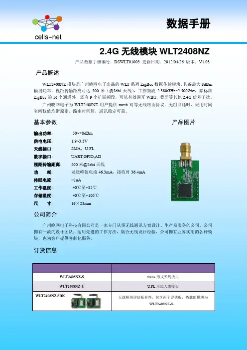
2.4G无线模块WLT2408NZ产品数据手册编号:DSWLT01003 更新日期:2012/04/26 版本:V1.03产品概述WLT2408NZ模块是广州晓网电子出品的WLT系列ZigBee数据传输模块,具备最大8dBm 输出功率,视距传输距离可达500米(@5dbi天线),工作频段2.380GHz~2.500Ghz,除标准ZigBee的16个通道外,还有9个扩展频段,可以有效避开WIFI、蓝牙等其他2.4G信号干扰。
广州晓网电子为WLT2408NZ用户提供mesh对等无线路由协议,无组网延时,采用时间空间权值均衡原则,路由时间短,通讯稳定可靠。
基本参数产品图片输出功率:供电电压:天线接口:数字接口:视距传输距离:功耗:休眠电流工作温度:存储温度:尺寸:-50~+8dBm1.9~3.3VSMA,U.FLUART,GPIO,AD500米@5dbi天线发送峰值电流46.3mA,接收时36.4mA <1uA-40℃至+85℃-40℃至+105℃16×23mm公司简介广州晓网电子科技有限公司是一家专门从事无线通讯方案设计、生产及服务的公司,公司拥有一流的设计团队,运用先进的工作方法,集合无线设计经验,公司拥有业界实用的各种模块,也为客户提供客制化服务。
订货信息WLT2408NZ-S SMA形式天线接头WLT2408NZ-U U.FL形式天线接头WLT2408NZ SDK 无线模块评估板套件,包含两个评估板,搭载的模块为WLT2408NZ-S。
数据手册版权声明本文档提供有关晓网电子产品的信息,并未授予任何知识产权的许可,并未以明示或暗示,或以禁止发言或其它方式授予任何知识产权许可,任何单位和个人未经版权所有者授权不得在任何形式的出版物中摘抄本手册内容。
产品命名规则图1-1 产品命名规则例如:WLT2408NZ-S表示晓网电子模块类的产品,频段为2.4GHz,理论输出功率为﹢8dBm(实际输出为﹢7.7dBm),超小封装,调制方式为ZigBee,外置SMA头的模块。
typedef struct{osal_event_hdr_t hdr; /* OSAL Message header *///OSAL消息头uint16 groupId; /* Message's group ID - 0 if not set *///消息组IDuint16 clusterId; /* Message's cluster ID *///消息族IDafAddrType_t srcAddr; /* Source Address, if endpoint isSTUBAPS_INTER_PAN_EP,it's an InterPAN message *///源地址类型uint16 macDestAddr; /* MAC header destination short address *///MAC物理地址uint8 endPoint; /* destination endpoint */ //目的端点uint8 wasBroadcast; /* TRUE if network destination was a broadcast address *///广播地址uint8 LinkQuality; /* The link quality of the received data frame */ //接收数据帧的链路质量uint8 correlation; /* The raw correlation value of the received data frame *///接收数据帧的未加工相关值。
int8 rssi; /* The received RF power in units dBm *///接收的射频功率。
uint8 SecurityUse; /* deprecated *///弃用uint32 timestamp; /* receipt timestamp from MAC *///收到时间标记。
数据的发送和接收一. 数据的发送在ZStack2006的协议栈中,我们只需调用函数AF_DataRequest()即可完成数据的发送。
afStatus.t AF_DataRequest( afAddrType_t 水dstAddr, endPointDesc_t *srcEP, uintl6 cID, uintl6 len, uint8 *buf, uint8 *transID. uint8 options, uint8radius )而我们在使用AF_DataRequest()函数时只需要了解其参数便可以非常灵活的以各种方式来发送数据。
AF_DataRequest()函数参数说明如下:*dstAddr ------------------- 发送口的地址、端点地址以及传送模式*srcEP .............................源端点cID-------------------------- 簇IDlen--------------------------- 数据长度*buf .................................数据*transID ..........................序歹U 号options --------------------- 发送选项radius ----------------------- 蚪匕数*dstAddr决定了消息发送到那个设备及那个endpoint,而簇ID(cID)决定了设备接收到信息如何处理。
簇可以理解为是一种约定,约定了信息怎么处理。
重要参数说明:1、地址afAddiType_ttypedef struct{union{uintl6 shortAddr; //短地址}addr;afAddrMode_taddrMode; 〃传送模式byteendPoint; 〃端点号}afAddrType_t;2、端点描述符endPointDesc_ttypedef struct{byteendPoint; // 端点号byte*task_id; 〃那一个任务的端点号SimpleDescriptionFormat_t*simpleDesc;// 简单的端点描述afNetworkLatencyReq_tlatencyReq;}endPointDesc_t;3、简单描述符SimpleDescriptionFormat_ttypedef structbyte EndPoint; //EPuintl6 AppProfld; 〃应用规范IDuintl6 AppDeviceld; 〃特定规范ID的设备类型byte AppDevVer:4; //特定规范ID的设备的版本byte Reserved:4; //AF_Vl_SUPPORTusesforAppFlags:4.byte AppNumlnClusters; //输入簇ID 的个数cld_t *pAppInClusterList; 〃输入簇ID 的列表byte AppNumOutClusters; //输出簇ID 的个数cld_t *pAppOutClusterList; //输出簇ID 的列表} SimpleDescriptionFormat_t;4、裱IDcIDClusterlD-具体应用吊ID5、发送选项options发送选项有如下选项#defineAF_FRAGMENTED 0x01#defineAF_ACK_REQUEST 0x10#defineAF_DISCV_ROUTE 0x20#defineAF_EN_SECURITY 0x40#defineAF_SKIP_ROUTING 0x80其中AF_ACK_REQUEST为发送后需要接收方的确认6、半径、条数radius传输跳数或传输半径,默认值为10数据发送模式说明:在协议栈数据发送模式有以下儿种:单播、组播、广播和直接发送四种模式。
JennicTECHNOLOGY FOR A CHANGING WORLDIntegrated Peripherals APIReference ManualJN-RM-2001Revision 2.318-Jun-2007JennicImportant NoticeJennic reserves the right to make corrections, modifications, enhancements, improvements and other changes to its products and services at any time, and to discontinue any product or service without notice. Customers should obtain the latest relevant information before placing orders, and should verify that such information is current and complete. All products are sold subject to Jennic’s terms and conditions of sale, supplied at the time of order acknowledgment. Information relating to device applications, and the like, is intended as suggestion only and may be superseded by updates. It is the customer’s responsibility to ensure that their application meets their own specifications. Jennic makes no representation and gives no warranty relating to advice, support or customer product design.Jennic assumes no responsibility or liability for the use of any of its products, conveys no license or title under any patent, copyright or mask work rights to these products, and makes no representations or warranties that these products are free from patent, copyright or mask work infringement, unless otherwise specified.Jennic products are not intended for use in life support systems/appliances or any systems where product malfunction can reasonably be expected to result in personal injury, death, severe property damage or environmental damage. Jennic customers using or selling Jennic products for use in such applications do so at their own risk and agree to fully indemnify Jennic for any damages resulting from such use.All trademarks are the property of their respective owners.2 © Jennic 2007 JN-RM-2001 (v2.3) 18-Jun-2007JennicContentsImportant Notice 2 Contents 3 About this Manual 7 Organisation 7 Conventions 7 Definitions, Acronyms and Abbreviations 81 Introduction 9 1.1 Scope 9readership 91.2 Intended2 API Description 10 2.1 General 10 2.1.1 u32AHI_Init 10Handling 10 2.2 InterruptControl 13 2.3 System2.3.1 u8AHI_PowerStatus 13 2.3.2 vAHI_MemoryHold 14 2.3.3 vAHI_CpuDoze 14 2.3.4 vAHI_PowerDown 14 2.3.5 vAHI_Sleep (JN513x Only) 15 2.3.6 vAHI_ProtocolPower 15 2.3.7 vAppApiSetBoostMode (JN513x Only) 16 2.3.8 vAHI_HighPowerModuleEnable (JN513x Only) 16 2.3.9 vAHI_ExternalClockEnable (JN513x Only) 16 2.3.10 vAHI_AntennaDiversityOutputEnable (JN513x Only) 17 2.3.11 vAHI_SysCtrlRegisterCallback 17 2.3.12 vAHI_SwReset 17Timers 18 2.4 Wake2.4.1 vAHI_WakeTimerEnable 18 2.4.2 vAHI_WakeTimerStart 18 2.4.3 vAHI_WakeTimerStop 18 2.4.4 u8AHI_WakeTimerStatus 19 2.4.5 u32AHI_WakeTimerCalibrate 19 2.4.6 u8AHI_WakeTimerFiredStatus 19Peripherals 20 2.5 Analogue2.5.1 vAHI_ApConfigure 20 2.5.2 bAHI_APRegulatorEnabled 21 2.5.3 vAHI_APRegisterCallback 21 2.6 ADC 22 2.6.1 vAHI_AdcEnable 22 2.6.2 vAHI_AdcStartSample 22 2.6.3 bAHI_AdcPoll 23 2.6.4 u16AHI_AdcRead 23 2.6.5 vAHI_AdcDisable 23 2.7 DACs 24 2.7.1 vAHI_DacEnable 24 2.7.2 bAHI_DacPoll 24JN-RM-2001 (v2.3) 18-Jun-2007 © Jennic 2007 3Jennic2.7.3 vAHI_DacOutput 25 2.7.4 vAHI_DacDisable 25 2.8 Comparators 26 2.8.1 vAHI_CompEnable 26 2.8.2 vAHI_ComparatorEnable (JN513x Only) 27 2.8.3 vAHI_CompDisable 27 2.8.4 vAHI_CompIntEnable 28 2.8.5 vAHI_CompWakeEnable 28 2.8.6 u8AHI_CompStatus 28 2.8.7 u8AHI_CompWakeStatus 28 2.9 DIO 29 2.9.1 vAHI_DioSetDirection 29 2.9.2 vAHI_DioSetOutput 30 2.9.3 u32AHI_DioReadInput 30 2.9.4 u8AHI_DioSetByte 30 2.9.5 u8AHI_DioReadByte 31 2.9.6 vAHI_DioSetPullup 31 2.9.7 vAHI_DioInterruptEdge 31 2.9.8 vAHI_DioInterruptEnable 32 2.9.9 u32AHI_DioInterruptStatus 32 2.10 UARTs 33 2.10.1 vAHI_UartEnable 33 2.10.2 vAHI_UartDisable 34 2.10.3 vAHI_UartSetClockDivisor 34 2.10.4 vAHI_UartSetBaudDivisor 34 2.10.5 vAHI_UartSetControl 35 2.10.6 vAHI_UartSetInterrupt 36 2.10.7 vAHI_UartSetRTSCTS (JN513x Only) 36 2.10.8 vAHI_UartReset 37 2.10.9 u8AHI_UartReadLineStatus 37 2.10.10 u8AHI_UartReadModemStatus 38 2.10.11 u8AHI_UartReadInterruptStatus 38 2.10.12 vAHI_UartWriteData 38 2.10.13 u8AHI_UartReadData 39 2.10.14 vAHI_Uart0RegisterCallback 39 2.10.15 vAHI_Uart1RegisterCallback 39 2.11 Timers 40 2.11.1 vAHI_TimerEnable 40 2.11.2 vAHI_TimerClockSelect 41 2.11.3 vAHI_TimerStartSingleShot 41 2.11.4 vAHI_TimerStartRepeat 42 2.11.5 vAHI_TimerStartDeltaSigma 42 2.11.6 vAHI_TimerStartCapture 43 2.11.7 vAHI_TimerReadCapture 43 2.11.8 vAHI_TimerStop 43 2.11.9 vAHI_TimerDisable 44Only) 44(JN513x2.11.10 vAHI_TimerDIOControl2.11.11 u8AHI_TimerFired 44 2.11.12 vAHI_Timer0RegisterCallback 45 2.11.13 vAHI_Timer1RegisterCallback 45 2.12 Tick Timer 464 © Jennic 2007 JN-RM-2001 (v2.3) 18-Jun-2007Jennic 2.12.1 vAHI_TickTimerInit 46 2.12.2 vAHI_TickTimerWrite 46 2.12.3 vAHI_TickTimerIntPendClr 46 2.12.4 bAHI_TickTimerIntStatus 46 2.12.5 vAHI_TickTimerConfigure 47 2.12.6 vAHI_TickTimerIntEnable 47 2.12.7 u32AHI_TickTimerRead 47 2.12.8 vAHI_TickTimerInterval 47 2.13 Serial Peripheral Interface 48 2.13.1 vAHI_SpiConfigure 48 2.13.2 vAHI_SpiReadConfiguration 49 2.13.3 vAHI_SpiRestoreConfiguration 49 2.13.4 vAHI_SpiSelect 49 2.13.5 vAHI_SpiStop 50 2.13.6 vAHI_SpiStartTransfer32 50 2.13.7 u32AHI_SpiReadTransfer32 50 2.13.8 vAHI_SpiStartTransfer16 50 2.13.9 u16AHI_SpiReadTransfer16 51 2.13.10 vAHI_SpiStartTransfer8 51 2.13.11 u8AHI_SpiReadTransfer8 51 2.13.12 bAHI_SpiPollBusy 51 2.13.13 vAHI_SpiWaitBusy 52 2.13.14 vAHI_SpiRegisterCallback 52 2.14 Serial Interface (2 Wire) 53 2.14.1 vAHI_SiConfigure 53 2.14.2 vAHI_SiSetCmdReg 54 2.14.3 vAHI_SiWriteData8 54 2.14.4 vAHI_SiWriteSlaveAddr 55 2.14.5 u8AHI_SiReadData8 55 2.14.6 bAHI_SiPollBusy 55 2.14.7 bAHI_SiPollTransferInProgress 55 2.14.8 bAHI_SiPollRxNack 56 2.14.9 bAHI_SiPollArbitrationLost 56 2.14.10 vAHI_SiRegisterCallback 56 2.15 Intelligent Peripheral Mode 57 2.15.1 vAHI_IpEnable 57 2.15.2 bAHI_IpSendData 57 2.15.3 bAHI_IpReadData 58 2.15.4 bAHI_IpTxDone 58 2.15.5 bAHI_IpRxDataAvailable 58 2.15.6 vAHI_IpRegisterCallback 58 2.16 Flash 59 2.16.1 bAHI_FlashInit (JN513x Only) 59 2.16.2 bAHI_FlashErase 59 2.16.3 bAHI_FlashEraseSector (JN513x Only) 60 2.16.4 bAHI_FlashProgram 60 2.16.5 bAHI_FullFlashProgram (JN513x Only) 61 2.16.6 bAHI_FlashRead 61 2.16.7 bAHI_FullFlashRead (JN513x Only) 62 References 63 JN-RM-2001 (v2.3) 18-Jun-2007 © Jennic 2007 5Jennic6 © Jennic 2007 JN-RM-2001 (v2.3) 18-Jun-2007JennicAbout this ManualThis manual describes the software Application Programming Interface (API) to the peripheral devices on the JN5121 and JN513x single-chip IEEE 802.15.4 compliant wireless microcontrollers. This is known as the Integrated Peripherals API. It details the calls that may be made through the API in order to set up, control and respond to events generated by the peripheral blocks, such as UARTs, general-purpose IO lines and timers among others. Setting up and using power saving modes are also covered.The software invoked by this API is present in the on-chip ROM. This API does not include support for the IEEE 802.15.4 MAC hardware built into the device; this hardware is controlled using the MAC software stack that is built into the on-chip ROM. Readers are recommended to refer to [1] for further information on the use of this feature.Note 1: This manual was previously known as the Hardware Peripheral Library Reference Manual.Note 2: This manual covers both the JN5121 and JN513x versions of the Integrated Peripherals API. Some of the API functions described in this manual are for the JN513x only - these are clearly marked.OrganisationThis document consists of two chapters.• Chapter 1 gives a brief overview of the scope of the manual• Chapter 2 describes in detail the calls available to control each feature of the deviceConventionsCode fragments or function prototypes are represented by Courier typeface. When referringto constants or functions defined in the code they are emboldened, like so.JN-RM-2001 (v2.3) 18-Jun-2007 © Jennic 2007 7JennicDefinitions, Acronyms and AbbreviationsACL Access Control ListADC Analogue to Digital Converter AES Advanced Encryption Standard AHI Application Hardware Interface API Application Programming Interface CPU Central Processor Unit CTS Clear-To-Send DAC Digital to Analogue Converter DIO Digital Input OutputFIFO First-In, First-Out queue MAC Medium Access Control PAN Personal Area Network PIB PAN Information Base PWM Pulse Width Modulation RAM Random Access Memory RTS Ready-To-SendSPI Serial Peripheral InterfaceUARTUniversal Asynchronous Receiver Transmitter8 © Jennic 2007 JN-RM-2001 (v2.3) 18-Jun-2007Jennic 1 Introduction1.1 ScopeThis document describes the Application Programming Interface (API) for the JN5121/JN513x hardware peripherals – the Integrated Peripherals API. Its functionality is as follows: • System Controller• Wake timers• Analogue to digital converter (ADC)• Digital to analogue converters (DACs)• Comparators• Digital Input/Output (DIO)• Universal asynchronous receiver-transmitters (serial ports) (UARTs)• Timers• Serial Peripheral Interface (SPI)• Serial Interface (2 Wire)• Tick Timer• External FLASH memoryNote 1: This API was previously known as the Hardware Peripheral Library or the Hardware API.Note 2: This manual covers both the JN5121 and JN513x versions of the Integrated Peripherals API. Some of the API functions described in this manual are for the JN513x only - these are clearly marked.This API (sometimes referred to in this document as the AHI) provides a thin layer above the registers used to control the JN5121/JN513x peripherals, by encapsulating several register accesses into one function call and hence making it easier to use the peripherals without having to acquire detailed knowledge of their operation.This document does not describe the Baseband Controller, Modem or Radio, as these are driven by the 802.15.4 Stack API, which is always provided with the JN5121 and JN513x devices. The 802.15.4 Stack API is described in [1].This document does not describe the API for features found on evaluation kit boards such as sensors or display panels, although the buttons and LEDs on the evaluation kit boards are connected to the GPIO pins on the JN5121/JN513x chip. The API for evaluation kit board features is described in [2].1.2 Intended readershipIt is assumed that the reader has a reasonable knowledge of ‘C’ programming.JN-RM-2001 (v2.3) 18-Jun-2007 © Jennic 2007 9Jennic2 API DescriptionThe API is described in terms of the functions it provides, and these are grouped by peripheral.The functions are defined in AppHardwareApi.h.Note: There are small differences in the Integrated Peripherals API for the JN5121 and JN513x chips. Some API functions are for the JN513x only - these are clearly marked in the section headings.2.1 General2.1.1 u32AHI_InitDeclaration PUBLIC uint32 u32AHI_Init(void);Inputs NoneOutputs 0 if initialisation failed, otherwise a 32-bit version number (most significant 16 bits are main revision, least significant 16 bits are minor revision)Description Used to initialise the AHI. This should be called after every reset or wake-up and before any other AHI calls are made. Note that the application API should havebeen initialised before this function is called, and the call to initialise theapplication API includes a parameter to register a function to call whenever aninterrupt from the peripherals occurs, see following section for details.2.2 Interrupt HandlingInterrupts from peripheral devices are handled by a set of device-specific callbacks. These canbe set within the Integrated Peripherals API by using the appropriate callback registrationroutines. For example the user can write their own UART interrupt handler and then register this routine using the vAHI_Uart0RegisterCallback function. All device-specific callback functions registered must have the following prototype:PRIVATE void vHwDeviceIntCallback(uint32 u32DeviceId, uint32 u32ItemBitmap)The device ID, u32DeviceId, is an enumerated value indicating the peripheral that generatedthe interrupt, as follows:Enumeration Interrupt Source Callback registration functionE_AHI_DEVICE_TICK_TIMER Tick Timer vAHI_TickTimerInitcontroller vAHI_SysCtrlRegisterCallback E_AHI_DEVICE_SYSCTRL SystemE_AHI_DEVICE_AES Encryption engine See JN-RM-2013-AES-Coprocessor-APIE_AHI_DEVICE_UART0 UART 0 vAHI_Uart0RegisterCallbackE_AHI_DEVICE_UART1 UART 1 vAHI_Uart1RegisterCallbackE_AHI_DEVICE_TIMER0 Timer 0 vAHI_Timer0RegisterCallbackE_AHI_DEVICE_TIMER1 Timer 1 vAHI_Timer1RegisterCallbackmaster vAHI_SpiRegisterCallback E_AHI_DEVICE_SPIM SPI10 © Jennic 2007 JN-RM-2001 (v2.3) 18-Jun-2007E_AHI_DEVICE_SI Serial Interface (2 wire) vAHI_SiRegisterCallbackvAHI_IpRegisterCallbackperipheralE_AHI_DEVICE_INTPER Intelligentperipherals vAHI_APRegisterCallbackE_AHI_DEVICE_ANALOGUE AnalogueThe item u32ItemBitmap is an enumerated value indicating the individual interrupt sourcewithin the peripheral, as described in the tables below.Before calling the callback function, the library clears the source of the interrupt, so there is no danger of the same interrupt causing the processor to enter a state of permanently trying to handle the same interrupt due to a malformed callback function. This also means that it is possible to have a NULL callback function.The UARTs are the exception to this rule; when generating a ‘receive data available’ or ‘timeout indication’ interrupt, the UARTs will only clear the interrupt when the data is read from the UART receive buffer. It is therefore vital that if UART interrupts are to be enabled, the callback function handles the ‘receive data available’ and ‘timeout indication’ interrupts by reading the data from the UART before returning.Note that if the Application Queue API is being used, the issue with UART interrupts is handled by the API, so the application does not have to cope with it. See [3] for more information about the Application Queue API.The enumerated values are defined as follows:TickTimerMask (Bit) Description0 Single source for Tick Timer interrupt, therefore returns 1 every time System ControllerMask (Bit) DescriptionE_AHI_SYSCTRL_COMP_MASK (29) Comparator eventsWake Timer eventsE_AHI_SYSCTRL_WK1_MASK (27)E_AHI_SYSCTRL_WK0_MASK (26)Digital IO eventsE_AHI_DIO20_INT (20)E_AHI_DIO19_INT (19)E_AHI_DIO18_INT (18)..E_AHI_DIO0_INT (0)UART (Identical for both UARTs)Enumerated Value DescriptionE_AHI_UART_TIMEOUT_MASK (6) Timeout indicationE_AHI_UART_RXLINE_MASK (3) Receive line statusE_AHI_UART_RXDATA_MASK (2) Receive data availableE_AHI_UART_TX_MASK (1) Transmit FIFO emptyE_AHI_UART_MODEM_MASK (0) Modem statusTimers (Identical for both timers)Mask (Bit) DescriptionE_AHI_TIMER_RISE_MASK (1) Interrupt status, generated on timer rising edge, end of low period - will benon-zero if interrupt for timer output going high has been setE_AHI_TIMER_PERIOD_MASK (0) Interrupt status, generated on timer falling edge, end of period - will benon-zero if interrupt for timer period complete has been setSerial Interface (2-wire)Mask (Bit) DescriptionE_AHI_SI_RXACK_MASK (7) Asserted if no acknowledge is received from the addressed slaveE_AHI_SI_BUSY_MASK (6) Asserted if a START signal is detectedCleared if a STOP signal is detectedE_AHI_SI_AL_MASK (5) Asserted to indicate loss of arbitrationE_AHI_SI_ACK_CTRL_MASK (2) Acknowledge control:0 indicates sent ACK1 indicates sent NACKE_AHI_SI_TIP_MASK (1) Asserted to indicate transfer in progressE_AHI_SI_INT_STATUS_MASK (0) Interrupt status; interrupt indicates loss of arbitration or that byte transferhas completedSPI MasterMask (Bit) DescriptionE_AHI_SPIM_TX_MASK (1) Asserted to indicate transfer has completedIntelligent PeripheralMask (Bit) DescriptionE_AHI_IP_INT_STATUS_MASK (6) Asserted to indicate transaction has completed, i.e slave select goes highand TXGO or RXGO has gone lowE_AHI_IP_TXGO_MASK (1) Asserted when TX data is copied to the internal buffer and cleared when ithas been sent out.E_AHI_IP_RXGO_MASK (0) Asserted when device is ready to receive state and cleared when data RXis complete.Analogue PeripheralsMask (Bit) DescriptionE_AHI_AP_INT_STATUS_MASK (0) Asserted to indicate capture complete or new sample ready2.3 System ControlThe system controller provides control for the CPU and memory power and sleep operation. There are two significant blocks in the system controller. The 32kHz domain runs from a simple oscillator and is designed for very low power sleep states. Whilst sleeping, the CPU does not run and relies on an interrupt to wake it up. The interrupt can be generated externally or from within the 32kHz domain. Later sections describe the ways in which interrupts can be generated within the chip, using the wake timers to generate events within the 32kHz domain or the DIO pins for external stimuli.The 16MHz domain is used to run the CPU and several peripherals (security engine, ADC, DACs, UARTs, timers and SPI master) and is used when the chip is fully operational. In this mode the 32kHz clock still runs and can be calibrated against the 16MHz clock to improve timing accuracy.The application is stored in Flash memory, and the contents are loaded into RAM when the device powers up. The RAM is powered by its own regulator, separate from the regulator for the CPU. This allows the RAM to remain powered when the CPU is asleep and powered down. This is useful for short sleep periods, when the time taken to re-load the RAM from flash is significant when compared to the sleep time. Alternatively, for longer sleep periods, the memory power may be removed as well, reducing the sleep current consumption.In addition, there are two other power domains, one for analogue peripherals and the other (the protocol domain) for the modem, encryption coprocessor, radio and baseband controller. The analogue power domain is switched on if the analogue peripherals are in use.As well as the normal sleep mode, it is possible to enter a deep sleep. In this state both the16MHz and 32kHz clock domains are turned off and the device can only be woken by the device reset line being pulled low.A final low power mode is doze mode, in which the CPU remains powered but the 16MHz clock to it is stopped. This uses more power than sleep mode but requires less time to restart. The CPU is brought out of doze mode by an interrupt (note that a tick timer interrupt cannot be used to bring the CPU out of doze mode).2.3.1 u8AHI_PowerStatusDeclaration PUBLIC uint8 u8AHI_PowerStatus(void);Inputs NoneOutputs uint8 containing power domain control settingsbit 0: 1 if chip has completed a sleep-wake up cyclebit 1: If 1 after wake up, memory contents were retained during sleepbit 2: 1 if analogue power domain is switched onbit 3: 1 if protocol power domain is switched onDescription Returns the power domain settings for the JN5121/JN513x, as described above.2.3.2 vAHI_MemoryHoldDeclaration PUBLIC void vAHI_MemoryHold(bool_t bHoldDuringSleep);Inputs bool_tbHoldDuringSleep TRUE to power memory during sleepFALSE to remove power from memory during sleepOutputs NoneDescription Determines whether the memory will remain powered during the next sleep period.2.3.3 vAHI_CpuDozeDeclaration PUBLIC void vAHI_CpuDoze(void);Inputs NoneOutputs NoneDescription Causes the CPU to stop operating until an interrupt occurs. The CPU clock will be disabled during sleep to minimise power consumption, although other modules willstill be operational. The function returns when the CPU re-starts.2.3.4 vAHI_PowerDownDeclaration PUBLIC void vAHI_PowerDown(bool_t bDeepNotNormalSleep);Inputs bool_tbDeepNotNormalSleep TRUE for the sleep to be deep sleep (device only awakes through a reset)FALSE for normal sleep (device wakes after interrupt or reset)Outputs NoneDescription Sends the device to sleep. In normal sleep mode, all parts of the device are inactive or powered down apart from the 32 kHz oscillator and those parts of thesystem controller used for wake up. In deep sleep, even these are powereddown. This function does not return. When the device restarts, it will beginprocessing at the reset vector.2.3.5 vAHI_Sleep (JN513x Only)Declaration PUBLIC void vAHI_Sleep(teAHI_SleepMode sSleepMode);Inputs teAHI_SleepModesSleepMode One of:E_AHI_SLEEP_OSCON_RAMON 32 kHz oscillator on and RAM onE_AHI_SLEEP_OSCON_RAMOFF 32 kHz oscillator on and RAM offE_AHI_SLEEP_OSCOFF_RAMON 32 kHz oscillator off and RAM onE_AHI_SLEEP_OSCOFF_RAMOFF 32 kHz oscillator off and RAM offE_AHI_SLEEP_DEEPDeep sleep (all components off)Outputs NoneDescription Sends the JN513x chip to sleep, allowing the 32 kHz oscillator and the RAM to be individually left on or switched off, as required. When in normal sleep mode, thedevice wakes after an interrupt or a reset. When in deep sleep mode, the devicewakes only after a reset. When the JN513x restarts, it will begin processing at thecold start or warm start entry point. This function does not return.2.3.6 vAHI_ProtocolPowerDeclaration PUBLIC void vAHI_ProtocolPower(bool_t bOnNotOff);Inputs bool_t bOnNotOff TRUE to turn the protocol power domain on.FALSE to turn the protocol power domain off. Outputs NoneDescription Controls the regulator that supplies the protocol domain (the radio, modem baseband and encryption coprocessor). If you intend to turn the protocol power offand then back on again without performing a reset, you must store the currentMAC settings before turning the protocol power off. You can save the MACsettings using the function vAppApiSaveMacSettings(). Turning the protocol powerback on can then be achieved simply by restoring the MAC settings using thefunction vAppApiRestoreMacSettings(). These functions are described in [1].While the protocol is powered down, you must not make any calls into the stack asthis may result in the stack trying to access the hardware (which is turned off) andtherefore a crash.2.3.7 vAppApiSetBoostMode (JN513x Only)Declaration PUBLIC void vAppApiSetBoostMode(bool_t bOnNotOff);Inputs bool_t bOnNotOff TRUE to enable boost mode.FALSE to disable boost mode (default setting). Outputs NoneDescription Enables or disables boost mode on a JN513x device – this increases the transmission power by approximately 3 dB (beware that this results in increasedcurrent consumption). A new setting only takes effect when the device isinitialised, so this function call must be followed by a call to either u32AppApiInit()or u32AppQApiInit(). The setting is maintained throughout sleep mode if memoryis held up, but is lost if memory is turned off.2.3.8 vAHI_HighPowerModuleEnable (JN513x Only)Declaration PUBLIC void vAHI_HighPowerModuleEnable(bool_t bRFTXEn,bool_t bRFRXEn);bool_t bRFTXEn TRUE to enable high power module transmitter InputsFALSE to disable high power module transmitter bool_t bRFRXEn TRUE to enable high power module receiverFALSE to disable high power module receiver Outputs NoneDescription Allows the transmitter and receiver sections of a High-Power Module (HPM) to be individually enabled or disabled. Must be called before using radio on an HPM.2.3.9 vAHI_ExternalClockEnable (JN513x Only)Declaration PUBLIC void vAHI_HighPowerModuleEnable(bool_t bExClockEn);Inputs bool_t bExClockEn TRUE to enable external clock inputFALSE to disable external clock inputOutputs NoneDescription Enables the use of an external source for the 32 kHz clock.2.3.10 vAHI_AntennaDiversityOutputEnable (JN513x Only)Declaration PUBLIC void vAHI_AntennaDiversityOutputEnable(bool_t bOddRetryOutEn,bool_t bEvenRetryOutEn);bool_t bOddRetryOutEn TRUE to enable output on DIO12FALSE to disable output on DIO12Inputsbool_t bEvenRetryOutEn TRUE to enable output on DIO13FALSE to disable output on DIO13Outputs NoneDescription Supports the provision of an alternative antenna in case of a transmission failure.DIO12 and DIO13 are each associated with an antenna, and are used to indicatewhether a transmission retry on the corresponding antenna is required. When bothDIOs are enabled for this feature, DIO13 goes high for the first transmission. If noacknowledgement is received, the need for a first retry of the transmission isindicated by DIO12 going high (DIO13 goes low). If required, a second retry isindicated by DIO13 going high (DIO12 goes low). Subsequently, all odd numberedretries are requested using DIO12 and all even numbered retries are requestedusing DIO13. The application must choose the antenna for each retry accordingly.2.3.11 vAHI_SysCtrlRegisterCallbackDeclaration PUBLIC void vAHI_SysCtrlRegisterCallback(PR_HWINT_APPCALLBACK prSysCtrlCallback);Inputs PR_HWINT_APPCALLBACKprSysCtrlCallback Pointer to function that is to be called when a system control interrupt occurs.Outputs NoneDescription Registers an application callback that will be called when the system control interrupt (caused by wake timer, comparator and DIO events) is triggered.2.3.12 vAHI_SwResetDeclaration PUBLIC void vAHI_SwReset (void);Inputs NoneOutputs NoneDescription Generates an internal reset when called, which completely re-starts the system.2.4 Wake TimersThe wake timers are normally used to time sleep periods and can be programmed to generate interrupts when the timeout period has completed. However, they can also be used whilst the CPU is running. There is another set of timers with more functionality that can operate only whilst the CPU is running; see Section 2.11.The wake timers run at a nominal 32kHz but to minimise complexity and hence power consumption, they may run at up to 30% fast or slow depending on temperature, supply voltage and manufacturing tolerance. A self-calibration facility is provided to time the 32kHz clock against the 16MHz clock if accurate timing is required.2.4.1 vAHI_WakeTimerEnableDeclaration PUBLIC void vAHI_WakeTimerEnable(uint8 u8Timer,bool_t bIntEnable);uint8 u8Timer Timer identity:E_AHI_WAKE_TIMER_0 orE_AHI_WAKE_TIMER_1Inputsbool_t bIntEnable TRUE to enable interrupt when timer fires FALSE to disable interruptOutputs NoneDescription Prepares a wake timer for use, enabling the associated interrupt if desired.2.4.2 vAHI_WakeTimerStartDeclaration PUBLIC void vAHI_WakeTimerStart(uint8 u8Timer, uint32 u32Count);uint8 u8Timer Timer identity:E_AHI_WAKE_TIMER_0 orE_AHI_WAKE_TIMER_1Inputsuint32 u32Count Count time in 32kHz periods, i.e. 32 is 1 millisecond Outputs NoneDescription Starts a wake timer to time for the specified interval.2.4.3 vAHI_WakeTimerStopDeclaration PUBLIC void vAHI_WakeTimerStop(uint8 u8Timer);Inputs uint8 u8Timer Timer identity:E_AHI_WAKE_TIMER_0 orE_AHI_WAKE_TIMER_1Outputs NoneDescription Stops a wake timer. No interrupt will be generated.2.4.4 u8AHI_WakeTimerStatusDeclaration PUBLIC uint8 u8AHI_WakeTimerStatus(void);Inputs NoneOutputs uint8 Bitmap:Returned value logical ANDed with E_AHI_WAKE_TIMER_MASK_0 will benon-zero if wake timer 0 is runningReturned value logical ANDed with E_AHI_WAKE_TIMER_MASK_1 will benon-zero if wake timer 1 is runningDescription Returns a bitmap where the relevant bits are set to show which timers are active.It is possible to have more than one timer active at once. Note that a timer remainsactive after the timed interval has completed.2.4.5 u32AHI_WakeTimerCalibrateDeclaration PUBLIC uint32 u32AHI_WakeTimerCalibrate(void);Inputs NoneOutputs uint32 Returned value shows the calibration offset from the ideal, measuredagainst the 16MHz clock. The ideal result would be 10000 decimal. Alower value means that the 32kHz clock is running fast and a highervalue means it is running slow.Description Performs a calibration of the 32kHz clock against the more accurate 16MHz clock.The returned value can be used to adjust the time interval values used to programthe wake timers.Note that the 32kHz clock has a tolerance of +/-30%.2.4.6 u8AHI_WakeTimerFiredStatusDeclaration PUBLIC uint8 u8AHI_WakeTimerFiredStatus(void);Inputs NoneOutputs uint8 Bitmap:Returned value logical ANDed with E_AHI_WAKE_TIMER_MASK_0 will benon-zero if wake timer 0 has firedReturned value logical ANDed with E_AHI_WAKE_TIMER_MASK_1 will benon-zero if wake timer 1 has firedDescription Returns a bitmap where the relevant bits are set to show which timers have fired.Any fired timer status is cleared as a result of this call.。
A Zigbee -subset/IEEE 802.15.4 Multi-platformProtocol StackDr. Robert B. Reese (reese@)Links: /~reese (homepage), (stack ) (C) Copyright by R. Reese, all rights reserved.Executive Summary: This document details the usage and implementation of a Zigbee-subset/IEEE 802.15.4 wireless stack, named MSSTATE_LRWPAN. Version 0.1 of the stack provides support for coordinator/router/RFD nodes, tree routing, direct messaging, and indirect messaging using static binding. Platforms currently supported are:• Platform: PICDEM Z (PIC18 + CC2420 radio), Compiler: MCC18 or HI-TECH• Platform: CC2430 Evaluation board/SOC_BB (CC2430/31 which has an 8051+802.15.4 Radio integrated in one die), Compiler: IAR51• Platform: WIN32 simulated RF nodes+ Virtual Board interface, Compiler: Microsoft Visual Studio .NET 2003This stack’s target audiences are educational, research, and hobbyist users who are looking to experiment with private personal-area networks using available Zigbee/802.15.4 platforms. This stack only implements a very small subset of the Zigbee 1.0 standard, and is not Zigbee compliant. Use of this stack is non-restricted for research, educational, and personal use. Commercial use of the NWK, APS, APL layers of this stack is bound by the Zigbee Trademarks, Designations, and Logos Policy [8] as these layers use Zigbee Alliance intellectual property.1. BackgroundMy name is Robert Reese, and I am an associate professor in the Electrical & Computer Engineering department at Mississippi State University. I first began experimenting with the Microchip Zigbee stack and the PICDEMZ platform in May 2005, and developed some examples over Summer 2005 to help our students use the PICDEMZ in senior design projects. During the Fall 2005 and Spring 2006 semesters, we had three senior teams use the PICDEMZ in their projects ([4][5][6]). In Fall 2006, I modified the Microchip 3.3 Stack to include security for use with the Wireless Inventory project ([4]) as a means to educate myself further on the internals of the Microchip stack, and the Zigbee [2] and 802.15.4 [1] standards. In May 2006, based upon the experience of helping our senior design teams use the Microchip stack, I decided to develop a new Zigee/802.15.4 software stack from scratch for the following reasons:• I wanted our students to be able to experiment with wireless platforms other than the Microchip PICDEMZ and the Microchip stack. Microchip gives users permission to use the Microchip stack only with Microchip processors (this is the principle reason for the new stack).• I looked at other options for wireless PANs such as TinyOS[7] and commercial Zigbee stacks. TinyOS is an impressive platform for wireless sensors, but it uses a C-based programming language called NesC that requires a modified-GCC compiler for your target CPU. Porting this environment to new platforms such as the ChipCon CC2430(8051+embedded radio) is non-trivial, and also the learning curve of NesC can bedaunting for senior design students. Commercial Zigbee stacks are an attractive option,except that you are limited to the platforms supported by them, and you generally cannotexperiment with their source code to try out new ideas.• Our student design teams do not need a full-featured Zigbee stack (at least at this time) –they used only a small subset of the available features in the Microchip stack.• There were some recurring problems with the Microchip stack that proved difficult to fix.The main problem was nodes losing connection because the radio would lock up or theprocessor would reset itself because of a watchdog timer reset (V3.3). It was a very time-consuming process to try to track down these problems; David Flowers at Microchip wasvery helpful during this time. However, we never did get the occasional networkdisconnects solved – the teams simply programmed their applications in a very defensivemanner to combat nodes becoming unable to talk on the network. Microchip may havesolved these problems in later stack releases, I don’t know as we had made manymodifications to the V3.3 stack and did not want to try correlating these changes withlater releases. The long debugging sessions with the Microchip stack made me wish foran environment in which I fully understood the implementation details and in which thestack debugging was easier. I do applaud Microchip’s effort at providing both a hardwareplatform (PICDEMZ) and a software stack for experimenting with Zigbee – it made ahuge difference in raising awareness of these topics within our ECE program. CarolPopovich, University Program Coordinator, helped in our Senior design projects bydonating two PICDEMZ boards over the ones that we had already purchased.Because of the above reasons, I have begun developing our own Zigbee-subset/802.15.4 stack, and this document details the implementation and usage of that stack. I have written this document as a way to help our students use this stack, and to help others outside of Mississippi State to use the stack if they are interested. I believe that the Microchip PICDEMZ platform is a nice platform for experimenting with wireless applications, and I hope that this stack stimulates additional interest in it for educational use.Table 1 compares the features in the current stack release against the Microchip Zigbee stack, V3.6. This table is provided as a reference for anybody considering using this stack in their own project – you easily see what the MSSTATE_LRWPAN stack code provides and what it does not provide.Table 1 Feature ListFeatureMicrochip Stack (V3.6) MSSTATE_LRWPAN Routing Mesh/Tree Tree Only Network Configuration Dynamic, network formed when nodesstartup and issuediscoveryDynamic, network formed whennodes startup and issue discovery PAN ID SelectionDynamic (Generated at startup) Static, assigned by userChannel SelectionDynamic, free channels searched at network start Static, assigned by user Frequency2.4GHz, 900MHz? 2.4GHz only Zigbee Message FormatKey/Value Pair, MSG MSG Direct MessagingYes, long/short addresses Yes, long/short addresses Binding, Indirect MessagesDynamic Binding, non-volatile binding table Static Binding only; in non-volatile table Beacon-enabled networksYES (?) NO Zigbee BroadcastYES NO APS acks for Messages YES YESPacket storage by Coord, router for nodes that are sleeping. YES NO, Coord/Router immediatelydelivers packets to destinationnodes.Zigbee Profiles YESNO Security NO NOPlatform/Compiler PICDEMZ/MCC18 (CC2420, UZ2400 radios) Restricted to Microchip processors. PICDEMZ/MCC18/HI-TECH C(CC2420 radio only)CC2430 (8051+RF radio)/AR51WIN32 Virtual Nodes/ Can be ported to other platforms for educational, research, hobbyist use.Zigbee Compliant YES NOAs is seen, the current feature set of the MSSTATE_LRWPAN stack is very limited compared to the Microchip stack. While more features will be added to the MSSTATE_LRWPAN stack over time (see the section on Future Releases), these features are sufficient for many student and hobbyist projects. At this time, I do not see this stack as ever becoming ‘Zigbee compliant’ or being promoted for commercial use, as this would require membership in the Zigbee Alliance as per the Zigbee Trademarks, Designations, and Logos Policy [8].2. TerminologyThis document assumes that you familiar with Zigbee/802.15.4 basic terminology. See the Zigbee[2] and 802.15.4 [1] standards for more information. The following terms/acronyms are used in this document:IEEE Address 8-byte 802.15.4 network address of a node, also called the long address Network Address 2-byte network address of a node, also called the short addressPAN personal area networkPAN ID : personal area network identifierFFD full function device (capable of routing)RFD reduced function deviceCoordinator The network coordinator, forms the networkHAL Hardware Abstraction Layer of the stackPHY Physical layer of the stackMAC Medium access control layer of the stackNWK Network layer of the stackAPS Application support layer of the stackAPL Application layer of the stackIDE Integrated Design EnvironmentSee Section 14 for a short description of Zigbee/802.15.4 networks.3. Installation, Directory OrganizationThe project files in the distribution assume that the file archive is unzipped to your top-level C:\ drive. The directory structure after the file archive is extracted is as follows:C:\msstate_lrwpan\msoft_net\virtual_board (Virtual Board application for WIN32 target )obj\compiletest\ (contains IDE project files, object files for target platforms)hitech_picdemz\iar51_cc2430\iar51_cc2430_soc_bb1\mcc18_picdemz\win32\src\simpletests\application test codestack\stack source code filestarget\ (contains HAL layer files for targets)iar51\cc2430_31\cc2430evb\mcc18\pic18\picdemz\win32\4. Target Platforms, Testing EnvironmentTable 2 gives the support platforms/compilers for the current version of the stack.Table 2 Support Platforms/CompilersPlatform CompilerConfigurationsTestedPICDEMZ(PIC184620+CC2420) MCC18/HI-TECHFour nodes – coordinator, routers, RFDsin various configurationsCC2430 EVB (Integrated 8501+Radio) IAR8051Three nodes (Coordinator + RFD). TheCC2430 nodes has also been used inconjunction with PICDEMZ nodes toform larger networks.WIN32 Virtual Nodes MS Visual .NET 2003 Five nodes – coordinator, routers, RFDs in various configurationsThe HAL layer of the stack assumes a platform that has a serial port, two pushbuttons, and two LEDs. When testing with PICDEMZ boards or the CC2430 boards, I used USB-to-serial port adapters to give me multiple serial ports, and Hyperterm as the serial console.The WIN32 Virtual nodes are a WIN32 console application plus a .NET GUI application called VirtualBoard that provides simulation of the pushbuttons, LEDs, and other debugging features (see the WIN32 quickstart for more information). The WIN32 Virtual node capability is useful for debugging new features of the stack as you can use the full power of the Visual Studio .NET environment for debugging. The virtual nodes use shared memory and mutexes to simulate the ether – I have simulated up to five nodes using this approach. More nodes could be simulated, but it can become somewhat cumbersome to bring up multiple console windows for the simulation. Also, I am unsure as to how well the shared memory approach scales as the number of nodes grow large – even though it works fine for small numbers of nodes there may be unanticipated contention problems for the mutex that controls access to the shared memory as the number of nodes increases, which may give undesired simulation results. I have used the WIN32 Virtual node capability extensively in developing this stack by using small numbers of virtual nodes, and have found it quite handy in tracking down problems. It is probably a good idea to test your application with a two or three Virtual nodes before trying it on actual hardware.Figure 1 shows a photograph of some of the nodes used in testing this stack.Figure 1 Current platforms that are compatible with this stack5. Example ApplicationsSeveral example applications can be found in the src\simpletests directory.Table 3 Example ApplicationsApplication Description ConfigurationsTestedhelloworld.c Used to test the UART functions ofthe HAL .Single node testboardest.c Used to test the LED, Switchfunctions of the HAL for the targetevaluation board.Single node testtimertest.c Used to test the LED, Switchfunctions of the HAL for the targetevaluation board.Single node testsleeptest.c Test of HAL sleep function Single node testmemtest.c Internal test for testing heapallocation functions in stack.Single node testping_pong.c An RFD sends a packet to acoordinator, and the coordinatorincrements a counter in the packetand sends it back. Can havemultiple RFDs sending packets.Uses direct messaging.Coord +RFDCoord + 2 RFDsCoord + Router + RFDCoord + Router + 2 RFDsCoord + 2 Routers + 2 RFDsping_pong_rejoin.c A more complex version ofping_pong.c that has rejoins/joins iffailures in TX/RX occurs.Same as ping_pong.ccoord_ep_indirect.c Tests indirect messaging betweenan endpoint on the Coordinator andand RFD.Intended as a two node testonly (Coord +RFD )direct_msg_test.c Tests different forms of directmessages from RFD to coordinator.Same as ping_pong.cindirect_msg_test.c Tests indirect messages betweentwo RFDs.Minimum configuration isthree nodes. Tested with:Coord + 2 RFDs.Coord + Router + RFDnode_sink.c Runs the stack, and prints out anypackets in the format used by theping_pong.c and rfd_sleep.cexamples.Single node application, afterjoining the network does nottransmit any packets.rfd_sleep.c Tests HAL sleep/wakeup functions– intended for use on an RFD nodethat sleeps between direct messagesends to a target node (default targetis Coordinator, but can be changedSame as ping_pong.cin the file). A good target node is one that is running the node_sink.c application so that you can see when the packet reaches the target.router_app.c A router application that canrecover from a dropped connectionwith its parent.Intended as the application torun on router nodes.The PingPong example is the default example that is linked into the project files for different targets and is the example discussed in the Quickstart sections.The PingPong example is the application that I like to leave running over night or over the weekend with four nodes (coord, router, two RFDs) to test long-term network stability. The current longest time that I have left nodes running is 72 hours, using PICDEMZ nodes. I use log files to track output, and occasionally I see the CC2420 on the PICDEMZ unable to perform a transmission, but on successive retries the nodes recover. I do not see nodes becoming unable to communicate on the network as I used to see in our applications on the V3.3 Microchip stack. I do not know the reason for this, all I know is that this stack appears to at least have a stable connection to the CC2420 on the PICDEMZ boards (similar stability has also been observed on the CC2430 nodes) The stack code itself is undoubtedly less stable in terms of higher stack functionality (routing, ill-formatted packets, etc.) than the Microchip stack because it simply has not been tested as much.6. QuickStarts for different platform targets6.1. WIN32 Target QuickStartThis section discusses how to simulate virtual hardware nodes under Windows. It assumes that you have Visual Studio .NET 2003 or later (the project files have been created with VS .NET 2003). Before trying a hardware target, it is a good idea to try out the WIN32 target first to get an idea of how the application is supposed to work.Steps to run the PingPong example.1. Start Visual Studio .NET and use File →Open →Project to open the solution named‘compiletest’ that is located at C:\msstate_lrwpan\obj\compiletest\win32. Ensure that the ping_pong.c file is linked as the sourcefile for this project.2. Use Build→Configuration Manager andselect the ‘coord’ configuration. UseBuild→Rebuild to rebuild the solution.Then use Debug→Start withoutDebugging to start the application.3. You should see a console window as seen below. This indicates the coordinator node hasstarted a network and is waiting for packets. The Address is the coordinator’s longaddress. This is set by the C++ preprocessor #defines in the compiletest property pages (use Project→compileTest Properties to open the property pages, browse to C/C++→Preprocessor , and look at the Preprocessor definitions – the #defines for aExtendedAddress_B0 (Least significant byte), aExtendedAddress_B1, etc. are used todefine the bytes of this node’s long address.Coordinator console:Property pages for compiletest, see the preprocessor definitions for #defines:When using the WIN32 nodes, the coordinator node always has to be started first as it createsthe shared memory segment used by all of the nodes. Starting a router or RFD node first willgenerate errors.4. Now use the configuration manager to select the RFD1 configuration, rebuild it, andlaunch the application. It should open a similar window, and you will see it join thecoordinator network. If Visual Studio does not let you change the configuration while thecoordinator console is opened, then this means that you started the coordinator withDEBUG enabled – you need to close the coordinator, and restart it without debugging.Observe that RFD1 has successfully joined the network.5. At this point, you need to start a Virtual Board application in order to simulate a switchpress to the RFD1 node. Launch the virtual_board.exe program found under C:\msstate_lrwpan\msoft_net\virtual_board\Debug. This will open a window as seen below:6. Type in the value ‘1’ to the EVB ID, and click on ‘Connect to EVBSim’. This willconnect the Virtual Board interface to the RFD1. The EVB ID in the RFD1 application is set by the #DEFINE EVB_ID in the compiletest property pages. This value must be unique for each console node – you can see this value printed in the Welcome message of the node in the shared memory name ‘EVBSMEM_1’ – the ‘1’ is the value of the EVB_ID of this node. After the Virtual Evaluation Board is connected, you will see something as shown below.The ‘connection succeeded!’ message indicates the Virtual Board was able to connect to the RFD1 console node. You could also open a Virtual Board for the coordinator, but it is unnecessary in this case as there is no switch interaction needed on the Coordinator node. Observe that LED1 is checked, this means that the RFD1 application has turned on LED1 (this is done by the RFD1 if it successfully joins a network).7. Click on ‘SW1’ checkbox. You should see the RFD1 and Coordinator start pingingpackets back and forth. You will also see the LED1 toggle each time a packet is received or a retry of packet send is attempted. To halt the nodes, you must close the applications.If you turn off all of the RFD nodes, the coordinator will begin constantly retrying sends of its last received packet, flooding the channel. A more robust version of the PingPong application can be found in ping_pong_rejoin.c.6.1.1. More about the PingPong application, Virtual BoardYou will observe that the PingCnt is incremented each time the packet is received by a node, so that when the PingCnt is printed on a node it advances by 2 each time since it was incremented by the remote node. The RXTimeouts is the number of times that a node timed out waiting for the packet to be returned by the coordinator – see section 8, “Stack Implementation Details”, for a discussion of stack internals and timeouts.. In the case of an RXTimeout, the node tries resending the packet (this is an application-level retry and is independent of the automatic retries at the MAC level). The TX stack latency is a measure of the latency from when the application issues the packet at the APL level to when the Radio begins transmitting – see Section 11 on Performance Tests for information on this value on the PICDEMZ and CC2430 targets.The DbgLev in the virtual board interface can be used to modify the debug_level variable in the connected node. If you set this value to 10, and then click on the WriteDgb button, you will see the console window begin printing out more details about internal stack operations, including dumping the packet contents of any packet that is transmitted. The stack code has a liberal sprinkling for debugging output statements that are conditionally controlled by the debug_level variable. A value of zero blocks any debugging output, higher values of debug_level increases the verbosity of the stack debugging output.The “Rx (enabled)” checkbox can be used to block RX to a node – you can use to simulate your node’s behavior in the case of excessive timeouts waiting for reception or excessive failures to receive MAC acks or APS acks.The ping_pong_rejoin.c application is a more complex version of ping_pong.c that performs network rejoins and joins on excessive TX or RX failures. Robust applications should probably do something similar in order to recover from dropped connections.6.1.2. Strategies for Creating Different Network TopologiesTo test various node Router/RFD combinations with the WIN32 nodes, one approach to use is: • Start the coordinator and a virtual board.• Start a router (either running the router_app.c or node_sink.c code – use the node_sink.c code if you do not want the router pinging its parent and thus creating more traffic for you to look through). Also start a virtual board for this router.• Before starting the next node or router, use the Virtual Board Rx checkbox to block the reception of all of the routers except for the router that you want the new node to join.Start up the new node, and verify that it joined the desired parent. If it did not, then just kill it, and make sure that you have the unwanted router(s) RX blocked, and try again. If the node joins the wrong router this creates an entry in that router’s neighbor table – when you kill the node that joined the wrong parent, this entry will still be in the table taking up space but it will not interfere with the network operation. It just means that the particular short address that was assigned to the node will not be reused until the router flushes its neighbor table by a join or the router is restarted.Be warned – Windows can get sluggish even with only a few nodes running – I have not tested the WIN32 virtual nodes with more than five nodes (coordinator, 2 routers, 2 RFDs) running at a time.To test the same node Router/RFD combinations with hardware platforms is more difficult if the nodes are all within range of each other. You can either customize the usrJoinVerifyCallback() function in each router to only accept a particular set of children, or you can try physically separating the nodes and seeing if the node joins the right router. Since a node joins a router based on the strongest signal strength, this is not too difficult to but requires starting/stopping a node several times and watching its console output to see if it joins the correct parent.6.2. PICDEMZ/MCC18 Target QuickStartBefore reading this section, please read the WIN32 Quickstart and experiment with the PingPong application on the virtual nodes as this section does not repeat information on the PingPong application.The project files in this archive were created with MPLAB V7.40.All project files are for the PICDEMZ target are located atC:\msstate_lrwpan\obj\compiletest\mcc18_picdemzSteps to run the PingPong example.1. Open MPLAB, and open the project named compiletest_coord.mcp project. Ensure thatthe file ping_pong.c is linked into the source files (if another sample application from Table 3 is linked in, then remove that file from the project and add the source file src/simpletests/ping_pong.c.2. Use Project→Clean to remove any pre-existing object files.3. Use Project→Build Options→Project and click on the MPLAB C18 target. You shouldsee:Replace the aExtendedAddress_B7 (MSB) through aExtendedAddress_B0 (LSB) Macro Definitions with the long address values of your the PICDEMZ node that will serve as the coordinator.4. Use Project→Make to build the application.5. Program your PICDEMZ with the resulting hex file –when you power the node up, youshould see the PingPong welcome message appear if you have a Hyperterminal window connected to the PICDEMZ node at 57600 baud.6. Close this project, and open the project named compiletest_rfd1.mcp – this project will beused to program the second PICDEMZ node as an RFD. Repeat steps 2 through 5 to specify this node’s long address, build the application and program the PICDEMZ node with your application.7. When you power up the RFD node, you should see its RA0 LED turn on indicating thatthe node connected to the network formed by the coordinator (this assumes the coordinator node is powered on). Press either RB5 or RB4 – you should start to see the RA0 LED blink on both the coordinator and RFD nodes as they ping the packet back and forth. You will also see the same status information printed on the WIN32 virtual node consoles dumped to the serial ports of the two nodes.Other project files supplied are:• compiletest_router.mcp - intended for a router node, has LRWPAN_ROUTER defined.• compiletest_rfd2.mcp - another RFD node.6.3. CC2430EVB/IAR51 QuickStartBefore reading this section, please read the WIN32 Quickstart and experiment with the PingPong application on the virtual nodes as this section does not repeat information on the PingPong application.The project files in this archive were created with IAR Embedded Workbench (IAREW) IDE, using the version available in July 2006.All workspace files are for the CC2430 EVB target are located at:C:\msstate_lrwpan\obj\compiletest\iar51_cc2430This assumes that you have two CC2430 Evaluation boards – one will run the coordinator, and one will run an RFD.Steps to run the PingPong example.1. Open IAREW, and open the workspace named compiletest.eww project.2. Select the coord configuration (coordinator configuration).3. Ensure that the file ping_pong.c is linked into the source files (if another sampleapplication from Table 3 is linked in, then remove that file from the project and add the source file src/simpletests/ping_pong.c.4. Use Project→Clean to remove any pre-existing object files.5. Click on the compiletest-coord entry at the top of the workspace file list, then useProject→Options to open the options for compiletest. Click on the C/C++ Compiler category, and then click on the Preprocessor tab, and you should see:Replace the aExtendedAddress_B7 (MSB) through aExtendedAddress_B0 (LSB) Macro Definitions with the long address values of your the PICDEMZ node that will serve as the coordinator.6. Use Project→Make to build the application.7. Program your PICDEMZ with the resulting hex file –when you power the node up, youshould see the PingPong welcome message appear if you have a Hyperterminal window connected to the PICDEMZ node at 57600 baud. I use the Chipcon SmartRF 04 Flash Programmer to program the hex file, and keep the target EVB IEEE address to the value that it was originally programmed with. I found it easiest to install the ChipCon Flash programmer as a subtool in the IAREW so that you can program the EVB from directly within the IAREW (the documentation on the Chipcon SmartRF 04 explains how to do this).8. Select the RFD configuration from within IAREW.9. Repeat steps 4 through 7 to specify this node’s long address, build the application andprogram the second CC2430 EVB node with your application.10. When you power up the RFD node, you should see its LED1 turn on indicating that thenode connected to the network formed by the coordinator (this assumes the coordinator node is powered on). Press the joystick either up or down (this simulates a button press of SW1 (up) or SW2 (down) – you should start to see the LED1 blink on both the coordinator and RFD nodes as they ping the packet back and forth. You will also see the。
Z igBee各个函数及路径和包涵各自的解释一各个Group的作用包含了应用层的内容和这个项目的主要内容,在协议栈里面一般是以操作系统的任务实现的。
1.APP:应用层目录,这是用户创建各种不同工程的区域,在这个目录中包2 .HAL:硬件层目录,包含有与硬件相关的配置和驱动及操作函数。
3.MAC:MAC 层目录,包含了MAC 层的参数配置文件及其MAC 的LIB库的函数接口文件。
4 .MT:实现通过串口可控各层,于各层进行直接交互。
5.NWK:网络层目录,含网络层配置参数文件及网络层库的函数接口文件,APS 层库的函数接口6.OSAL:协议栈的操作系统。
7.Profile:AF 层目录,包含AF 层处理函数文件。
8.Security:安全层目录,安全层处理函数,比如加密函数等9.Services:地址处理函数目录,包括着地址模式的定义及地址处理函数。
10.Tools:工程配置目录,包括空间划分及ZStack 相关配置信息。
11.ZDO :目录。
12.ZMac:MAC 层目录,包括MAC 层参数配置及MAC 层LIB 库函数回调处理函数。
13.ZMain:主函数目录,包括入口函数及硬件配置文件。
14.Output:输出文件目录,这个EW8051 IDE 自动生成的。
二.各Group所有文件的“完整路径”及其功能描述1.函数:OSAL_TransmitApp.cOURS-IOTV2-CC2530(8)\OURS-CC2530\OURS_CC2530LIB\lib15(APP2_ZigBee( ZStack))\APP2_ZigBee(ZStack)\OURS-ZStack(ptop)\Projects\zstack\IAR_file\Trans mit\Source功能:提供应用于TransmitApp所需的操作系统接口2函数:AF.h完整路径OURS-IOTV2-CC2530(8)\OURS-CC2530\OURS_CC2530LIB\lib15(APP2_ZigBee (ZStack))\APP2_ZigBee(ZStack)\OURS-ZStack(ptop)\Components\stack\af Description: This file contains the Application Framework definitions.(此文件包含应用程序框架定义。
JennicTECHNOLOGY FOR A CHANGING WORLDIntegrated Peripherals APIReference ManualJN-RM-2001Revision 2.318-Jun-2007JennicImportant NoticeJennic reserves the right to make corrections, modifications, enhancements, improvements and other changes to its products and services at any time, and to discontinue any product or service without notice. Customers should obtain the latest relevant information before placing orders, and should verify that such information is current and complete. All products are sold subject to Jennic’s terms and conditions of sale, supplied at the time of order acknowledgment. Information relating to device applications, and the like, is intended as suggestion only and may be superseded by updates. It is the customer’s responsibility to ensure that their application meets their own specifications. Jennic makes no representation and gives no warranty relating to advice, support or customer product design.Jennic assumes no responsibility or liability for the use of any of its products, conveys no license or title under any patent, copyright or mask work rights to these products, and makes no representations or warranties that these products are free from patent, copyright or mask work infringement, unless otherwise specified.Jennic products are not intended for use in life support systems/appliances or any systems where product malfunction can reasonably be expected to result in personal injury, death, severe property damage or environmental damage. Jennic customers using or selling Jennic products for use in such applications do so at their own risk and agree to fully indemnify Jennic for any damages resulting from such use.All trademarks are the property of their respective owners.2 © Jennic 2007 JN-RM-2001 (v2.3) 18-Jun-2007JennicContentsImportant Notice 2 Contents 3 About this Manual 7 Organisation 7 Conventions 7 Definitions, Acronyms and Abbreviations 81 Introduction 9 1.1 Scope 9readership 91.2 Intended2 API Description 10 2.1 General 10 2.1.1 u32AHI_Init 10Handling 10 2.2 InterruptControl 13 2.3 System2.3.1 u8AHI_PowerStatus 13 2.3.2 vAHI_MemoryHold 14 2.3.3 vAHI_CpuDoze 14 2.3.4 vAHI_PowerDown 14 2.3.5 vAHI_Sleep (JN513x Only) 15 2.3.6 vAHI_ProtocolPower 15 2.3.7 vAppApiSetBoostMode (JN513x Only) 16 2.3.8 vAHI_HighPowerModuleEnable (JN513x Only) 16 2.3.9 vAHI_ExternalClockEnable (JN513x Only) 16 2.3.10 vAHI_AntennaDiversityOutputEnable (JN513x Only) 17 2.3.11 vAHI_SysCtrlRegisterCallback 17 2.3.12 vAHI_SwReset 17Timers 18 2.4 Wake2.4.1 vAHI_WakeTimerEnable 18 2.4.2 vAHI_WakeTimerStart 18 2.4.3 vAHI_WakeTimerStop 18 2.4.4 u8AHI_WakeTimerStatus 19 2.4.5 u32AHI_WakeTimerCalibrate 19 2.4.6 u8AHI_WakeTimerFiredStatus 19Peripherals 20 2.5 Analogue2.5.1 vAHI_ApConfigure 20 2.5.2 bAHI_APRegulatorEnabled 21 2.5.3 vAHI_APRegisterCallback 21 2.6 ADC 22 2.6.1 vAHI_AdcEnable 22 2.6.2 vAHI_AdcStartSample 22 2.6.3 bAHI_AdcPoll 23 2.6.4 u16AHI_AdcRead 23 2.6.5 vAHI_AdcDisable 23 2.7 DACs 24 2.7.1 vAHI_DacEnable 24 2.7.2 bAHI_DacPoll 24JN-RM-2001 (v2.3) 18-Jun-2007 © Jennic 2007 3Jennic2.7.3 vAHI_DacOutput 25 2.7.4 vAHI_DacDisable 25 2.8 Comparators 26 2.8.1 vAHI_CompEnable 26 2.8.2 vAHI_ComparatorEnable (JN513x Only) 27 2.8.3 vAHI_CompDisable 27 2.8.4 vAHI_CompIntEnable 28 2.8.5 vAHI_CompWakeEnable 28 2.8.6 u8AHI_CompStatus 28 2.8.7 u8AHI_CompWakeStatus 28 2.9 DIO 29 2.9.1 vAHI_DioSetDirection 29 2.9.2 vAHI_DioSetOutput 30 2.9.3 u32AHI_DioReadInput 30 2.9.4 u8AHI_DioSetByte 30 2.9.5 u8AHI_DioReadByte 31 2.9.6 vAHI_DioSetPullup 31 2.9.7 vAHI_DioInterruptEdge 31 2.9.8 vAHI_DioInterruptEnable 32 2.9.9 u32AHI_DioInterruptStatus 32 2.10 UARTs 33 2.10.1 vAHI_UartEnable 33 2.10.2 vAHI_UartDisable 34 2.10.3 vAHI_UartSetClockDivisor 34 2.10.4 vAHI_UartSetBaudDivisor 34 2.10.5 vAHI_UartSetControl 35 2.10.6 vAHI_UartSetInterrupt 36 2.10.7 vAHI_UartSetRTSCTS (JN513x Only) 36 2.10.8 vAHI_UartReset 37 2.10.9 u8AHI_UartReadLineStatus 37 2.10.10 u8AHI_UartReadModemStatus 38 2.10.11 u8AHI_UartReadInterruptStatus 38 2.10.12 vAHI_UartWriteData 38 2.10.13 u8AHI_UartReadData 39 2.10.14 vAHI_Uart0RegisterCallback 39 2.10.15 vAHI_Uart1RegisterCallback 39 2.11 Timers 40 2.11.1 vAHI_TimerEnable 40 2.11.2 vAHI_TimerClockSelect 41 2.11.3 vAHI_TimerStartSingleShot 41 2.11.4 vAHI_TimerStartRepeat 42 2.11.5 vAHI_TimerStartDeltaSigma 42 2.11.6 vAHI_TimerStartCapture 43 2.11.7 vAHI_TimerReadCapture 43 2.11.8 vAHI_TimerStop 43 2.11.9 vAHI_TimerDisable 44Only) 44(JN513x2.11.10 vAHI_TimerDIOControl2.11.11 u8AHI_TimerFired 44 2.11.12 vAHI_Timer0RegisterCallback 45 2.11.13 vAHI_Timer1RegisterCallback 45 2.12 Tick Timer 464 © Jennic 2007 JN-RM-2001 (v2.3) 18-Jun-2007Jennic 2.12.1 vAHI_TickTimerInit 46 2.12.2 vAHI_TickTimerWrite 46 2.12.3 vAHI_TickTimerIntPendClr 46 2.12.4 bAHI_TickTimerIntStatus 46 2.12.5 vAHI_TickTimerConfigure 47 2.12.6 vAHI_TickTimerIntEnable 47 2.12.7 u32AHI_TickTimerRead 47 2.12.8 vAHI_TickTimerInterval 47 2.13 Serial Peripheral Interface 48 2.13.1 vAHI_SpiConfigure 48 2.13.2 vAHI_SpiReadConfiguration 49 2.13.3 vAHI_SpiRestoreConfiguration 49 2.13.4 vAHI_SpiSelect 49 2.13.5 vAHI_SpiStop 50 2.13.6 vAHI_SpiStartTransfer32 50 2.13.7 u32AHI_SpiReadTransfer32 50 2.13.8 vAHI_SpiStartTransfer16 50 2.13.9 u16AHI_SpiReadTransfer16 51 2.13.10 vAHI_SpiStartTransfer8 51 2.13.11 u8AHI_SpiReadTransfer8 51 2.13.12 bAHI_SpiPollBusy 51 2.13.13 vAHI_SpiWaitBusy 52 2.13.14 vAHI_SpiRegisterCallback 52 2.14 Serial Interface (2 Wire) 53 2.14.1 vAHI_SiConfigure 53 2.14.2 vAHI_SiSetCmdReg 54 2.14.3 vAHI_SiWriteData8 54 2.14.4 vAHI_SiWriteSlaveAddr 55 2.14.5 u8AHI_SiReadData8 55 2.14.6 bAHI_SiPollBusy 55 2.14.7 bAHI_SiPollTransferInProgress 55 2.14.8 bAHI_SiPollRxNack 56 2.14.9 bAHI_SiPollArbitrationLost 56 2.14.10 vAHI_SiRegisterCallback 56 2.15 Intelligent Peripheral Mode 57 2.15.1 vAHI_IpEnable 57 2.15.2 bAHI_IpSendData 57 2.15.3 bAHI_IpReadData 58 2.15.4 bAHI_IpTxDone 58 2.15.5 bAHI_IpRxDataAvailable 58 2.15.6 vAHI_IpRegisterCallback 58 2.16 Flash 59 2.16.1 bAHI_FlashInit (JN513x Only) 59 2.16.2 bAHI_FlashErase 59 2.16.3 bAHI_FlashEraseSector (JN513x Only) 60 2.16.4 bAHI_FlashProgram 60 2.16.5 bAHI_FullFlashProgram (JN513x Only) 61 2.16.6 bAHI_FlashRead 61 2.16.7 bAHI_FullFlashRead (JN513x Only) 62 References 63 JN-RM-2001 (v2.3) 18-Jun-2007 © Jennic 2007 5Jennic6 © Jennic 2007 JN-RM-2001 (v2.3) 18-Jun-2007JennicAbout this ManualThis manual describes the software Application Programming Interface (API) to the peripheral devices on the JN5121 and JN513x single-chip IEEE 802.15.4 compliant wireless microcontrollers. This is known as the Integrated Peripherals API. It details the calls that may be made through the API in order to set up, control and respond to events generated by the peripheral blocks, such as UARTs, general-purpose IO lines and timers among others. Setting up and using power saving modes are also covered.The software invoked by this API is present in the on-chip ROM. This API does not include support for the IEEE 802.15.4 MAC hardware built into the device; this hardware is controlled using the MAC software stack that is built into the on-chip ROM. Readers are recommended to refer to [1] for further information on the use of this feature.Note 1: This manual was previously known as the Hardware Peripheral Library Reference Manual.Note 2: This manual covers both the JN5121 and JN513x versions of the Integrated Peripherals API. Some of the API functions described in this manual are for the JN513x only - these are clearly marked.OrganisationThis document consists of two chapters.• Chapter 1 gives a brief overview of the scope of the manual• Chapter 2 describes in detail the calls available to control each feature of the deviceConventionsCode fragments or function prototypes are represented by Courier typeface. When referringto constants or functions defined in the code they are emboldened, like so.JN-RM-2001 (v2.3) 18-Jun-2007 © Jennic 2007 7JennicDefinitions, Acronyms and AbbreviationsACL Access Control ListADC Analogue to Digital Converter AES Advanced Encryption Standard AHI Application Hardware Interface API Application Programming Interface CPU Central Processor Unit CTS Clear-To-Send DAC Digital to Analogue Converter DIO Digital Input OutputFIFO First-In, First-Out queue MAC Medium Access Control PAN Personal Area Network PIB PAN Information Base PWM Pulse Width Modulation RAM Random Access Memory RTS Ready-To-SendSPI Serial Peripheral InterfaceUARTUniversal Asynchronous Receiver Transmitter8 © Jennic 2007 JN-RM-2001 (v2.3) 18-Jun-2007Jennic 1 Introduction1.1 ScopeThis document describes the Application Programming Interface (API) for the JN5121/JN513x hardware peripherals – the Integrated Peripherals API. Its functionality is as follows: • System Controller• Wake timers• Analogue to digital converter (ADC)• Digital to analogue converters (DACs)• Comparators• Digital Input/Output (DIO)• Universal asynchronous receiver-transmitters (serial ports) (UARTs)• Timers• Serial Peripheral Interface (SPI)• Serial Interface (2 Wire)• Tick Timer• External FLASH memoryNote 1: This API was previously known as the Hardware Peripheral Library or the Hardware API.Note 2: This manual covers both the JN5121 and JN513x versions of the Integrated Peripherals API. Some of the API functions described in this manual are for the JN513x only - these are clearly marked.This API (sometimes referred to in this document as the AHI) provides a thin layer above the registers used to control the JN5121/JN513x peripherals, by encapsulating several register accesses into one function call and hence making it easier to use the peripherals without having to acquire detailed knowledge of their operation.This document does not describe the Baseband Controller, Modem or Radio, as these are driven by the 802.15.4 Stack API, which is always provided with the JN5121 and JN513x devices. The 802.15.4 Stack API is described in [1].This document does not describe the API for features found on evaluation kit boards such as sensors or display panels, although the buttons and LEDs on the evaluation kit boards are connected to the GPIO pins on the JN5121/JN513x chip. The API for evaluation kit board features is described in [2].1.2 Intended readershipIt is assumed that the reader has a reasonable knowledge of ‘C’ programming.JN-RM-2001 (v2.3) 18-Jun-2007 © Jennic 2007 9Jennic2 API DescriptionThe API is described in terms of the functions it provides, and these are grouped by peripheral.The functions are defined in AppHardwareApi.h.Note: There are small differences in the Integrated Peripherals API for the JN5121 and JN513x chips. Some API functions are for the JN513x only - these are clearly marked in the section headings.2.1 General2.1.1 u32AHI_InitDeclaration PUBLIC uint32 u32AHI_Init(void);Inputs NoneOutputs 0 if initialisation failed, otherwise a 32-bit version number (most significant 16 bits are main revision, least significant 16 bits are minor revision)Description Used to initialise the AHI. This should be called after every reset or wake-up and before any other AHI calls are made. Note that the application API should havebeen initialised before this function is called, and the call to initialise theapplication API includes a parameter to register a function to call whenever aninterrupt from the peripherals occurs, see following section for details.2.2 Interrupt HandlingInterrupts from peripheral devices are handled by a set of device-specific callbacks. These canbe set within the Integrated Peripherals API by using the appropriate callback registrationroutines. For example the user can write their own UART interrupt handler and then register this routine using the vAHI_Uart0RegisterCallback function. All device-specific callback functions registered must have the following prototype:PRIVATE void vHwDeviceIntCallback(uint32 u32DeviceId, uint32 u32ItemBitmap)The device ID, u32DeviceId, is an enumerated value indicating the peripheral that generatedthe interrupt, as follows:Enumeration Interrupt Source Callback registration functionE_AHI_DEVICE_TICK_TIMER Tick Timer vAHI_TickTimerInitcontroller vAHI_SysCtrlRegisterCallback E_AHI_DEVICE_SYSCTRL SystemE_AHI_DEVICE_AES Encryption engine See JN-RM-2013-AES-Coprocessor-APIE_AHI_DEVICE_UART0 UART 0 vAHI_Uart0RegisterCallbackE_AHI_DEVICE_UART1 UART 1 vAHI_Uart1RegisterCallbackE_AHI_DEVICE_TIMER0 Timer 0 vAHI_Timer0RegisterCallbackE_AHI_DEVICE_TIMER1 Timer 1 vAHI_Timer1RegisterCallbackmaster vAHI_SpiRegisterCallback E_AHI_DEVICE_SPIM SPI10 © Jennic 2007 JN-RM-2001 (v2.3) 18-Jun-2007E_AHI_DEVICE_SI Serial Interface (2 wire) vAHI_SiRegisterCallbackvAHI_IpRegisterCallbackperipheralE_AHI_DEVICE_INTPER Intelligentperipherals vAHI_APRegisterCallbackE_AHI_DEVICE_ANALOGUE AnalogueThe item u32ItemBitmap is an enumerated value indicating the individual interrupt sourcewithin the peripheral, as described in the tables below.Before calling the callback function, the library clears the source of the interrupt, so there is no danger of the same interrupt causing the processor to enter a state of permanently trying to handle the same interrupt due to a malformed callback function. This also means that it is possible to have a NULL callback function.The UARTs are the exception to this rule; when generating a ‘receive data available’ or ‘timeout indication’ interrupt, the UARTs will only clear the interrupt when the data is read from the UART receive buffer. It is therefore vital that if UART interrupts are to be enabled, the callback function handles the ‘receive data available’ and ‘timeout indication’ interrupts by reading the data from the UART before returning.Note that if the Application Queue API is being used, the issue with UART interrupts is handled by the API, so the application does not have to cope with it. See [3] for more information about the Application Queue API.The enumerated values are defined as follows:TickTimerMask (Bit) Description0 Single source for Tick Timer interrupt, therefore returns 1 every time System ControllerMask (Bit) DescriptionE_AHI_SYSCTRL_COMP_MASK (29) Comparator eventsWake Timer eventsE_AHI_SYSCTRL_WK1_MASK (27)E_AHI_SYSCTRL_WK0_MASK (26)Digital IO eventsE_AHI_DIO20_INT (20)E_AHI_DIO19_INT (19)E_AHI_DIO18_INT (18)..E_AHI_DIO0_INT (0)UART (Identical for both UARTs)Enumerated Value DescriptionE_AHI_UART_TIMEOUT_MASK (6) Timeout indicationE_AHI_UART_RXLINE_MASK (3) Receive line statusE_AHI_UART_RXDATA_MASK (2) Receive data availableE_AHI_UART_TX_MASK (1) Transmit FIFO emptyE_AHI_UART_MODEM_MASK (0) Modem statusTimers (Identical for both timers)Mask (Bit) DescriptionE_AHI_TIMER_RISE_MASK (1) Interrupt status, generated on timer rising edge, end of low period - will benon-zero if interrupt for timer output going high has been setE_AHI_TIMER_PERIOD_MASK (0) Interrupt status, generated on timer falling edge, end of period - will benon-zero if interrupt for timer period complete has been setSerial Interface (2-wire)Mask (Bit) DescriptionE_AHI_SI_RXACK_MASK (7) Asserted if no acknowledge is received from the addressed slaveE_AHI_SI_BUSY_MASK (6) Asserted if a START signal is detectedCleared if a STOP signal is detectedE_AHI_SI_AL_MASK (5) Asserted to indicate loss of arbitrationE_AHI_SI_ACK_CTRL_MASK (2) Acknowledge control:0 indicates sent ACK1 indicates sent NACKE_AHI_SI_TIP_MASK (1) Asserted to indicate transfer in progressE_AHI_SI_INT_STATUS_MASK (0) Interrupt status; interrupt indicates loss of arbitration or that byte transferhas completedSPI MasterMask (Bit) DescriptionE_AHI_SPIM_TX_MASK (1) Asserted to indicate transfer has completedIntelligent PeripheralMask (Bit) DescriptionE_AHI_IP_INT_STATUS_MASK (6) Asserted to indicate transaction has completed, i.e slave select goes highand TXGO or RXGO has gone lowE_AHI_IP_TXGO_MASK (1) Asserted when TX data is copied to the internal buffer and cleared when ithas been sent out.E_AHI_IP_RXGO_MASK (0) Asserted when device is ready to receive state and cleared when data RXis complete.Analogue PeripheralsMask (Bit) DescriptionE_AHI_AP_INT_STATUS_MASK (0) Asserted to indicate capture complete or new sample ready2.3 System ControlThe system controller provides control for the CPU and memory power and sleep operation. There are two significant blocks in the system controller. The 32kHz domain runs from a simple oscillator and is designed for very low power sleep states. Whilst sleeping, the CPU does not run and relies on an interrupt to wake it up. The interrupt can be generated externally or from within the 32kHz domain. Later sections describe the ways in which interrupts can be generated within the chip, using the wake timers to generate events within the 32kHz domain or the DIO pins for external stimuli.The 16MHz domain is used to run the CPU and several peripherals (security engine, ADC,timing accuracy.device powers up. The RAM is powered by its own regulator, separate from the regulator for the CPU. This allows the RAM to remain powered when the CPU is asleep and powered down. This is useful for short sleep periods, when the time taken to re-load the RAM from flash is significant when compared to the sleep time. Alternatively, for longer sleep periods, the memory power may be removed as well, reducing the sleep current consumption.In addition, there are two other power domains, one for analogue peripherals and the other (the protocol domain) for the modem, encryption coprocessor, radio and baseband controller. The analogue power domain is switched on if the analogue peripherals are in use.As well as the normal sleep mode, it is possible to enter a deep sleep. In this state both the16MHz and 32kHz clock domains are turned off and the device can only be woken by the device reset line being pulled low.A final low power mode is doze mode, in which the CPU remains powered but the 16MHz clock to it is stopped. This uses more power than sleep mode but requires less time to restart. The CPU is brought out of doze mode by an interrupt (note that a tick timer interrupt cannot be used to bring the CPU out of doze mode).2.3.1 u8AHI_PowerStatusDeclaration PUBLIC uint8 u8AHI_PowerStatus(void);Inputs NoneOutputs uint8 containing power domain control settingsbit 0: 1 if chip has completed a sleep-wake up cyclebit 1: If 1 after wake up, memory contents were retained during sleepbit 2: 1 if analogue power domain is switched onbit 3: 1 if protocol power domain is switched onDescription Returns the power domain settings for the JN5121/JN513x, as described above.2.3.2 vAHI_MemoryHoldDeclaration PUBLIC void vAHI_MemoryHold(bool_t bHoldDuringSleep);Inputs bool_tbHoldDuringSleep TRUE to power memory during sleepFALSE to remove power from memory during sleepOutputs NoneDescription Determines whether the memory will remain powered during the next sleep period.2.3.3 vAHI_CpuDozeDeclaration PUBLIC void vAHI_CpuDoze(void);Inputs NoneOutputs NoneDescription Causes the CPU to stop operating until an interrupt occurs. The CPU clock will be disabled during sleep to minimise power consumption, although other modules willstill be operational. The function returns when the CPU re-starts.2.3.4 vAHI_PowerDownDeclaration PUBLIC void vAHI_PowerDown(bool_t bDeepNotNormalSleep);Inputs bool_tbDeepNotNormalSleep TRUE for the sleep to be deep sleep (device only awakes through a reset)FALSE for normal sleep (device wakes after interrupt or reset)Outputs NoneDescription Sends the device to sleep. In normal sleep mode, all parts of the device are inactive or powered down apart from the 32 kHz oscillator and those parts of thesystem controller used for wake up. In deep sleep, even these are powereddown. This function does not return. When the device restarts, it will beginprocessing at the reset vector.2.3.5 vAHI_Sleep (JN513x Only)Declaration PUBLIC void vAHI_Sleep(teAHI_SleepMode sSleepMode);Inputs teAHI_SleepModesSleepMode One of:E_AHI_SLEEP_OSCON_RAMON 32 kHz oscillator on and RAM onE_AHI_SLEEP_OSCON_RAMOFF 32 kHz oscillator on and RAM offE_AHI_SLEEP_OSCOFF_RAMON 32 kHz oscillator off and RAM onE_AHI_SLEEP_OSCOFF_RAMOFF 32 kHz oscillator off and RAM offE_AHI_SLEEP_DEEPDeep sleep (all components off)Outputs NoneDescription Sends the JN513x chip to sleep, allowing the 32 kHz oscillator and the RAM to be individually left on or switched off, as required. When in normal sleep mode, thedevice wakes after an interrupt or a reset. When in deep sleep mode, the devicewakes only after a reset. When the JN513x restarts, it will begin processing at thecold start or warm start entry point. This function does not return.2.3.6 vAHI_ProtocolPowerDeclaration PUBLIC void vAHI_ProtocolPower(bool_t bOnNotOff);Inputs bool_t bOnNotOff TRUE to turn the protocol power domain on.FALSE to turn the protocol power domain off. Outputs NoneDescription Controls the regulator that supplies the protocol domain (the radio, modem baseband and encryption coprocessor). If you intend to turn the protocol power offand then back on again without performing a reset, you must store the currentMAC settings before turning the protocol power off. You can save the MACsettings using the function vAppApiSaveMacSettings(). Turning the protocol powerback on can then be achieved simply by restoring the MAC settings using thefunction vAppApiRestoreMacSettings(). These functions are described in [1].While the protocol is powered down, you must not make any calls into the stack asthis may result in the stack trying to access the hardware (which is turned off) andtherefore a crash.2.3.7 vAppApiSetBoostMode (JN513x Only)Declaration PUBLIC void vAppApiSetBoostMode(bool_t bOnNotOff);Inputs bool_t bOnNotOff TRUE to enable boost mode.FALSE to disable boost mode (default setting). Outputs NoneDescription Enables or disables boost mode on a JN513x device – this increases the transmission power by approximately 3 dB (beware that this results in increasedcurrent consumption). A new setting only takes effect when the device isinitialised, so this function call must be followed by a call to either u32AppApiInit()or u32AppQApiInit(). The setting is maintained throughout sleep mode if memoryis held up, but is lost if memory is turned off.2.3.8 vAHI_HighPowerModuleEnable (JN513x Only)Declaration PUBLIC void vAHI_HighPowerModuleEnable(bool_t bRFTXEn,bool_t bRFRXEn);bool_t bRFTXEn TRUE to enable high power module transmitter InputsFALSE to disable high power module transmitter bool_t bRFRXEn TRUE to enable high power module receiverFALSE to disable high power module receiver Outputs NoneDescription Allows the transmitter and receiver sections of a High-Power Module (HPM) to be individually enabled or disabled. Must be called before using radio on an HPM.2.3.9 vAHI_ExternalClockEnable (JN513x Only)Declaration PUBLIC void vAHI_HighPowerModuleEnable(bool_t bExClockEn);Inputs bool_t bExClockEn TRUE to enable external clock inputFALSE to disable external clock inputOutputs NoneDescription Enables the use of an external source for the 32 kHz clock.2.3.10 vAHI_AntennaDiversityOutputEnable (JN513x Only)Declaration PUBLIC void vAHI_AntennaDiversityOutputEnable(bool_t bOddRetryOutEn,bool_t bEvenRetryOutEn);bool_t bOddRetryOutEn TRUE to enable output on DIO12FALSE to disable output on DIO12Inputsbool_t bEvenRetryOutEn TRUE to enable output on DIO13FALSE to disable output on DIO13Outputs NoneDescription Supports the provision of an alternative antenna in case of a transmission failure.DIO12 and DIO13 are each associated with an antenna, and are used to indicatewhether a transmission retry on the corresponding antenna is required. When bothDIOs are enabled for this feature, DIO13 goes high for the first transmission. If noacknowledgement is received, the need for a first retry of the transmission isindicated by DIO12 going high (DIO13 goes low). If required, a second retry isindicated by DIO13 going high (DIO12 goes low). Subsequently, all odd numberedretries are requested using DIO12 and all even numbered retries are requestedusing DIO13. The application must choose the antenna for each retry accordingly.2.3.11 vAHI_SysCtrlRegisterCallbackDeclaration PUBLIC void vAHI_SysCtrlRegisterCallback(PR_HWINT_APPCALLBACK prSysCtrlCallback);Inputs PR_HWINT_APPCALLBACKprSysCtrlCallback Pointer to function that is to be called when a system control interrupt occurs.Outputs NoneDescription Registers an application callback that will be called when the system control interrupt (caused by wake timer, comparator and DIO events) is triggered.2.3.12 vAHI_SwResetDeclaration PUBLIC void vAHI_SwReset (void);Inputs NoneOutputs NoneDescription Generates an internal reset when called, which completely re-starts the system.2.4 Wake TimersThe wake timers are normally used to time sleep periods and can be programmed to generate interrupts when the timeout period has completed. However, they can also be used whilst the CPU is running. There is another set of timers with more functionality that can operate only whilst the CPU is running; see Section 2.11.The wake timers run at a nominal 32kHz but to minimise complexity and hence power consumption, they may run at up to 30% fast or slow depending on temperature, supply voltage and manufacturing tolerance. A self-calibration facility is provided to time the 32kHz clock against the 16MHz clock if accurate timing is required.2.4.1 vAHI_WakeTimerEnableDeclaration PUBLIC void vAHI_WakeTimerEnable(uint8 u8Timer,bool_t bIntEnable);uint8 u8Timer Timer identity:E_AHI_WAKE_TIMER_0 orE_AHI_WAKE_TIMER_1Inputsbool_t bIntEnable TRUE to enable interrupt when timer fires FALSE to disable interruptOutputs NoneDescription Prepares a wake timer for use, enabling the associated interrupt if desired.2.4.2 vAHI_WakeTimerStartDeclaration PUBLIC void vAHI_WakeTimerStart(uint8 u8Timer, uint32 u32Count);uint8 u8Timer Timer identity:E_AHI_WAKE_TIMER_0 orE_AHI_WAKE_TIMER_1Inputsuint32 u32Count Count time in 32kHz periods, i.e. 32 is 1 millisecond Outputs NoneDescription Starts a wake timer to time for the specified interval.2.4.3 vAHI_WakeTimerStopDeclaration PUBLIC void vAHI_WakeTimerStop(uint8 u8Timer);Inputs uint8 u8Timer Timer identity:E_AHI_WAKE_TIMER_0 orE_AHI_WAKE_TIMER_1Outputs NoneDescription Stops a wake timer. No interrupt will be generated.2.4.4 u8AHI_WakeTimerStatusDeclaration PUBLIC uint8 u8AHI_WakeTimerStatus(void);Inputs NoneOutputs uint8 Bitmap:Returned value logical ANDed with E_AHI_WAKE_TIMER_MASK_0 will benon-zero if wake timer 0 is runningReturned value logical ANDed with E_AHI_WAKE_TIMER_MASK_1 will benon-zero if wake timer 1 is runningDescription Returns a bitmap where the relevant bits are set to show which timers are active.It is possible to have more than one timer active at once. Note that a timer remainsactive after the timed interval has completed.2.4.5 u32AHI_WakeTimerCalibrateDeclaration PUBLIC uint32 u32AHI_WakeTimerCalibrate(void);Inputs NoneOutputs uint32 Returned value shows the calibration offset from the ideal, measuredagainst the 16MHz clock. The ideal result would be 10000 decimal. Alower value means that the 32kHz clock is running fast and a highervalue means it is running slow.Description Performs a calibration of the 32kHz clock against the more accurate 16MHz clock.The returned value can be used to adjust the time interval values used to programthe wake timers.Note that the 32kHz clock has a tolerance of +/-30%.2.4.6 u8AHI_WakeTimerFiredStatusDeclaration PUBLIC uint8 u8AHI_WakeTimerFiredStatus(void);Inputs NoneOutputs uint8 Bitmap:Returned value logical ANDed with E_AHI_WAKE_TIMER_MASK_0 will benon-zero if wake timer 0 has firedReturned value logical ANDed with E_AHI_WAKE_TIMER_MASK_1 will benon-zero if wake timer 1 has firedDescription Returns a bitmap where the relevant bits are set to show which timers have fired.Any fired timer status is cleared as a result of this call.。