泄漏率测试微小气体流量计使用说明书_V100
- 格式:pdf
- 大小:527.42 KB
- 文档页数:9
测量小气体质量流量计安全操作及保养规程1. 引言测量小气体质量流量计是一种用于测量气体流量的设备。
本文档旨在提供测量小气体质量流量计的安全操作指南及保养规程,以确保设备的正常运行和长期稳定性。
2. 安全操作规程在使用测量小气体质量流量计前,请务必遵守以下安全操作规程:2.1 穿戴个人防护装备在操作测量小气体质量流量计时,请穿戴合适的个人防护装备,包括但不限于眼镜、手套和防护服等。
这样可以最大程度地减少意外伤害的风险。
2.2 定期检查设备在使用测量小气体质量流量计之前,请定期检查设备的外观是否有明显的损坏或破损。
如果发现设备有问题,请及时联系维修人员进行修复或更换。
2.3 避免超载操作使用测量小气体质量流量计时,请确保不要超过设备的最大负荷能力。
超载操作可能会导致设备损坏或误差增大。
2.4 避免使用不合格的气体使用测量小气体质量流量计时,请务必使用合格的气体。
不合格的气体可能含有有害物质,会对设备造成损坏或影响测量结果的准确性。
2.5 确保稳定环境在操作测量小气体质量流量计时,请确保周围环境稳定。
避免设备暴露在高温、潮湿或有腐蚀性的环境中,以免对设备造成损坏。
2.6 正确连接设备在连接测量小气体质量流量计时,请确保连接头与设备正确对接,并紧固好连接螺丝。
确保连接牢固可以避免泄漏和错误的测量结果。
2.7 正确操作设备在操作测量小气体质量流量计时,请按照设备使用说明书中的操作步骤进行。
避免操作错误可能会导致设备损坏或测量结果的不准确。
2.8 定期校准设备为了保证测量结果的准确性,请定期校准测量小气体质量流量计。
校准可以帮助设备恢复准确的测量能力,并检测设备是否存在问题。
3. 保养规程为了保持测量小气体质量流量计的长期稳定性和性能,以下是一些保养规程的建议:3.1 清洁设备定期清洁测量小气体质量流量计可以避免灰尘和污垢的积累,影响设备的精度和测量结果的准确性。
使用柔软的布擦拭设备外壳和连接头,避免使用有腐蚀性的化学品。
便携气体流量计使用方法我折腾了好久便携气体流量计的使用方法,总算找到点门道。
一开始我拿到这个便携气体流量计的时候,真的是一头雾水,就像面对一个完全未知的小怪兽似的。
我就知道是测气体流量的,但是从哪开始呢?我先看到上面有一些按键,就像手机按键一样,但是每个按键代表什么我完全不知道。
我就乱按一通,结果显示屏上的数据乱跳,也不知道哪个才是正确的流量值,这就是我第一次失败的尝试。
后来我静下心来仔细看说明书,说明书上那一堆专业术语啊,看着就头疼。
但是咬着牙看下去,我发现有个很重要的东西就是它的测量单位的设置。
它可以用不同的单位来显示流量,你要是没设置对,那得到的数据根本就没法用。
这就好比你用一把尺子量东西,但是你不知道这尺子标的是厘米还是英寸,量出来的结果肯定乱套。
还有啊,我发现这个便携气体流量计在使用的时候得注意放置的位置和方向。
我试过一次把它斜着放,测出来的数据就很奇怪。
就像你拿一个杯子接水,你要是歪着放,那水进到杯子里的情况就不对了,这个道理差不多。
它一定要水平放置,这样气体通过的时候才是正常的测量状态。
再就是那个探头之类的东西,如果不干净或者有东西堵住了,那测量也是不准确的。
我有次没注意清理,测了好多次都觉得结果差得离谱。
后来才发现是探头有点脏东西,清理之后就正常多了。
所以在使用之前一定要检查探头的情况。
这个流量计还有一个校准的功能,不过我对这个校准功能还不是特别确定。
我试过按照说明书上说的方法校准,但是感觉校准之后的数据和我预期的还是有点小偏差。
但我想可能是我自己操作还有不熟练的地方。
另外,在连接气体源的时候,一定要连接紧密。
我有次没拧紧,就漏了一点气,虽然漏的不多,但是测出来的数据就是不对。
这就好比你用吸管喝饮料,要是吸管没插紧,边喝边漏气,那你喝到嘴里的量肯定不对嘛。
反正,使用便携气体流量计,就是要把这些小细节都注意到,慢慢试,不要像我一开始那样瞎按一通,多看看说明书,多尝试,遇到问题多思考,慢慢就能掌握它的使用方法了。
微型气体流量计气体流量计安全操作及保养规程微型气体流量计是一种可靠、精确、方便、实用的气体流量检测仪器,适用于对燃气、液化气、空气和其他非腐蚀性气体的流量检测。
为了确保气体流量计的安全和稳定运行,必须严格遵守相关的安全操作规程和保养规程。
安全操作规程1.在使用微型气体流量计之前,请仔细阅读相关说明书和使用手册,确保您已经掌握了相应的操作方法。
2.使用气体流量计时,请务必注意以下的安全事项:–请勿将微型气体流量计暴露在高温、潮湿或有腐蚀性的环境中。
–在连接气源之前,请检查气路和电路是否正确连接,以免出现电击或气体泄漏等危险情况。
–请勿在微型气体流量计和其他电气设备之间接通高压电源,以免出现漏电或短路等事故。
–在使用气体流量计进行气体检测时,请务必佩戴防护眼镜和手套,以免因气体泄漏而导致眼部和手部受伤。
–请勿将微型气体流量计拆卸或更换零部件,以免出现故障或操作错误等安全问题。
3.使用气体流量计时,请遵守以下的操作流程:–首先,请打开气源并调整气流量,将气体流量调整到适当的值。
–然后,请将气路和电路连接好,并进行调试,确保气体流量计能够正常工作。
–使用气体流量计时,请保持其干燥、清洁和安全,避免恶劣的工作环境和不必要的干扰。
保养规程为了确保微型气体流量计的长期稳定运行,必须定期对其进行保养和维护,以下为一些保养规程:1.定期检查气体流量计的机体、管路和连接部分是否存在泄漏、磨损、锈蚀等情况,及时进行修复和更换。
2.定期更换微型气体流量计中的各种滤网、橡胶垫和密封圈等易损件,保持气路畅通和密封性能良好。
3.定期清洗微型气体流量计的外表面和工作面,保持其清洁和干燥,避免堵塞和氧化等问题。
4.定期校准微型气体流量计的读数精度和偏差值,保证其稳定性和准确性。
总之,使用微型气体流量计时,必须严格按照相关的安全操作规程和保养规程进行操作和保养。
只有这样,才能保证气体流量计的安全、稳定和长期可靠的工作。
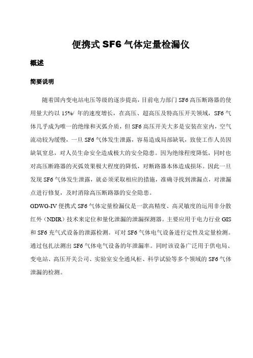
便携式SF6气体定量检漏仪概述简要说明随着国内变电站电压等级的逐步提高,目前电力部门SF6高压断路器的使用量大约以15%/ 年的速度增长,在高压、超高压及特高压开关领域,SF6气体几乎成为唯一的绝缘和灭弧介质,但SF6高压开关大多是安装在室内,空气流动较为缓慢,一旦SF6气体发生泄露,容易造成局部缺氧,致使工作人员因缺氧窒息,对人员生命安全造成极大的安全隐患。
因为绝缘程度降低,同时也对高压断路器的灭弧效果极大程度的降低,对断路器本体造成损坏。
因此一旦发现SF6气体发生泄露,就必须采取相应的措施,准确寻找到泄漏点,对泄漏点进行修复,及时消除高压断路器的安全隐患。
GDWG-IV便携式SF6气体定量检漏仪是一款高精度、高灵敏度的运用非分散红外(NDIR)技术来定位和量化泄漏的泄漏探测器。
主要应用于电力行业GIS 和SF6充气式设备的泄露检测。
可对SF6气体电气设备进行定性及定量检测。
通过包扎法测出SF6气体电气设备的年泄漏率。
同时该设备广泛用于供电局、变电站、高压开关公司、实验室安全通风柜、科学试验等多个领域的SF6气体泄漏的检测。
应用范围● 高压开关设备● 直升飞机转子叶片● 气体输送系统● 检测灭火器● 建筑物通风率研究● 检测危险物● 贮存容器产品优势★无放射源,无辐射危险★无需耗材,无需定期更换高压高纯氩气★无接近高压气体的危险★无需定期更换传感器,无须二次投资,性价比高★性能稳定,维护费用低。
无需每年做线性校准无易损件★不受湿度影响,不受环境污染影响,无本底影响误差★高灵敏度探测泄露可达0.1ppmv★严重泄露或SF6浓度达到100%时不会污染或损坏检测器引用标准1、DL/T 639-1997 六氟化硫电气设备运行、试验及检修人员安全防护细则2、GB11023-89高压开关设备六氟化硫气体密封试验方法3、DLT846.6-2004 六氟化硫气体检漏仪4、国电公司72号附件3[1999] 高压开关设备质量监督管理办法5、GB/T 17626 电磁兼容试验和测量技术6、GB/T 2423电工电子产品环境试验7、DL/T596电力设备预防性试验规程8、GB/T 6388 运输包装收发货标志仪器标准配置技术特点1. 能对SF6电气设备的泄露进行定性及定量的检测。
气体流量计的使用方法气体流量计是一种用于测量流经管道的气体的仪器。
它们广泛应用于工业、化工、医药、环保等领域。
正确使用气体流量计对于获得准确的流量数据至关重要。
以下是气体流量计的使用方法。
1. 安装在安装气体流量计之前,需要根据实际情况选择合适的安装位置。
安装位置应远离其他设备或管道,以避免干扰。
同时,须确保安装位置的管道直线段长度足够,这有助于获得准确的测量结果。
2. 连接将气体流量计与管道相连接时,应注意使用正确的连接方式。
一般来说,常用的连接方式有法兰连接和螺纹连接。
根据实际需要选择适当的连接方式,并确保连接紧固牢固以防止泄漏。
3. 预热在开始使用气体流量计之前,需要进行预热。
预热的目的是使气体流量计处于稳定工作状态,以获得准确的测量数据。
预热时,应根据气体流量计的规格和使用要求,将流通系统逐渐加热至操作温度。
4. 校准为了提高气体流量计的准确性,定期进行校准是必要的。
校准可以通过与标准流量计进行比对来完成。
在校准过程中,应根据流体的性质和使用环境调整校准参数,以确保测量结果的准确性和可靠性。
5. 操作在实际使用气体流量计时,需要注意以下几点:- 避免过载:确定气体流量计的测量范围,避免超过其额定流量范围,以免对仪器造成损坏。
- 清洁维护:定期清洁气体流量计以保持其正常工作状态。
注意,清洁时应使用适当的清洁剂,并避免损坏仪器。
- 防护措施:根据气体流量计的要求,采取必要的防护措施,如防雷、防腐蚀等,以延长仪器的使用寿命。
- 监测记录:记录使用过程中的各项数据,如流量变化、温度、压力等,以备后续分析与比对。
6. 故障排除如果在使用过程中遇到气体流量计工作异常的情况,应及时进行故障排除。
常见的故障可能包括传感器故障、连接问题等。
在进行故障排除时,应先检查连接是否松动或损坏,排除连接问题后再检查其他可能的故障原因。
总结:气体流量计的使用方法涉及到安装、连接、预热、校准、操作和故障排除等多个方面。
气体流量计操作说明一、引言气体流量计是一种用于测量气体流量的仪器。
它广泛应用于工业生产、实验室测试以及其他领域。
本文将详细介绍气体流量计的操作步骤,以帮助用户正确、准确地使用该设备。
二、气体流量计的组成气体流量计主要由以下几个部分组成:1. 测量管道:用于气体流经的通道,具有一定的直径和长度。
2. 流量传感器:用于感知气体的流动,并将其转化为电子信号。
3. 显示屏:用于显示气体流量的数值和单位。
4. 控制面板:用于设置和调整流量计的参数和功能。
三、气体流量计的操作步骤1. 准备工作:在开始操作之前,请确保以下几项工作已完成:- 将气体流量计放置在平稳的工作台面上,避免受到外部振动的干扰。
- 确保电源线正确连接,并插入可靠的电源插座。
- 检查测量管道是否畅通,并不存在任何堵塞或泄漏情况。
2. 打开气体流量计:按下电源开关,启动气体流量计。
等待一段时间,待设备完成自检程序后,显示屏将显示当前环境中的气体流量数值。
3. 设置流量单位:根据实际需求,通过控制面板上的菜单按钮进入设置界面。
选择合适的流量单位,例如标准立方米每小时(Nm³/h)或标准立方英尺每分钟(SCFM),并确认设置。
4. 校准流量计:定期校准气体流量计以确保其测量精度。
具体的校准步骤可以参考设备附带的操作指南或联系供应商进行咨询。
5. 测量气体流量:将待测气体通过测量管道引入气体流量计中。
确保气体的流动平稳,没有剧烈的波动或停顿。
观察显示屏上的流量数值,记录下所需的数据。
6. 停止使用:在使用完成后,将气体流量计的电源开关调至关闭位置,断开电源供应。
注意,应遵循设备的关闭顺序,以免损坏各个部件。
四、注意事项1. 气体流量计应在干燥、无腐蚀性气体的环境中使用,以免损坏设备。
2. 在操作过程中,应避免剧烈碰撞或摔落气体流量计,以免对其造成损坏。
3. 如果发现气体流量计表面有任何液体溅落,请立即断开电源,并检查是否存在泄漏或其他安全隐患。
流量计使用指南说明书一、产品简介流量计是一种用于测量液体或气体的流量的仪器,它广泛应用于工业、农业、石油、化工等领域。
本产品使用指南将为用户提供准确详细的操作步骤,助您正确使用流量计,提高工作效率。
二、安装要求1. 选择合适的位置:流量计应安装在离主管道适当距离的稳定位置,以确保测量的准确性。
2. 连接管道:将流量计与管道进行牢固连接,接口应严密,不得有泄漏。
3. 起始调零:在使用流量计之前,应进行起始调零操作,以确保后续测量的准确性。
三、操作步骤1. 打开流量计电源,并确认指示灯是否亮起。
2. 进入菜单界面,依次设置测量单位、流速范围和报警参数等,根据实际需要进行调整。
3. 进行测量操作:根据流量计的型号和功能,选择合适的测量方法,按照相应步骤进行操作。
4. 确认测量结果:流量计将显示实时测量结果,确保结果准确可靠。
5. 关闭流量计电源,结束使用。
四、常见问题解决方法1. 测量结果异常:检查是否有漏气或漏液现象,重新校准流量计,保持管道清洁。
2. 操作错误:仔细阅读说明书,按照操作步骤进行操作。
3. 存储异常:检查流量计的存储功能是否正常,如有问题,请联系厂家技术支持。
五、维护保养1. 定期清洁流量计:使用软布擦拭流量计外壳,确保表面干净整洁。
2. 避免冲击:流量计为精密仪器,应避免剧烈震动或冲击,防止损坏。
3. 定期校准:根据使用频率和要求,定期对流量计进行校准,确保测量结果准确可靠。
六、安全注意事项1. 使用过程中如发现异常情况或故障,应立即停止使用,并联系专业人员进行维修或更换。
2. 避免流量计被高温、低温、潮湿或腐蚀性物质所接触,以免损坏设备。
3. 请勿未经授权进行拆卸或维修,以免造成二次损伤。
七、售后服务本公司提供完善的售后服务,在保修期内,对质量问题提供免费维修或更换服务。
详细的售后服务政策请参考售后服务文件。
八、结束语本使用指南仅为流量计用户操作提供参考,并不能包含所有细节和情况。
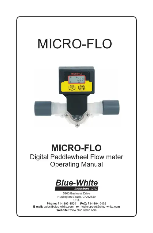
MICRO-FLODigital Paddlewheel Flow meterOperating Manual5300 Business Drive Huntington Beach, CA 92649USAPhone: 714-893-8529 FAX: 714-894-9492E mail:********************or **************************Website: Blue-WhiteIndustries, Ltd.MICRO-FLOPage 21.0IntroductionThe Micro-Flo flowmeter is designed to display flow rate and flow total on a six digit LCD display. The meter can measure bi-directional flows in either vertical or horizontal mounting orientation. Six flow ranges and four optional pipe and tubing connections are available. Pre-programmedcalibration K-factors can be selected for the corresponding flow range or a custom field calibration can be performed for higher accuracy at a specific flow rate. The meter is factory programmed for the correct K-factor ofthe body size included with the meter.TABLE OF CONTENTS1.....Introduction ....................................................................................22.....Features ..........................................................................................33.....Model number matrix ....................................................................34.....Specifications . (4)4.1..Temperature and pressure limits................................................44.2..Dimensions...............................................................................54.3..Replacement parts.....................................................................55.....Installation .. (6)5.1..Wiring connections...................................................................65.2..Circuit board connections.........................................................65.3..Flow verification output signal..................................................65.4..Panel or wall mountings............................................................76.....Operation . (7)6.1..Theory of operation...................................................................76.2..Control panel............................................................................86.3..Flow stream requirements.........................................................86.4..Run mode display......................................................................86.5..Run mode operation..................................................................96.6..Viewing the K-factor.................................................................97.....Programming . (9)7.1..Field Calibration.......................................................................97.2..Programming for body size/range S1 - S6.................................107.3..Field calibration range setting S0..............................................11Warranty information .. (12)2.0Features!Four connection options available:1/8” F/NPT, 1/4” F/NPT, 1/4” OD x .170 ID Tubing & 3/8” OD x 1/4” ID Tubing sizes.!Six body size/flow range options available:30 to 300 ml/min, 100 to 1000 ml/min, 200 to 2000 ml/min, 300 to 3000 ml/min, 500 to 5000 ml/min, 700 to 7000 ml/min.!3 model display variations:FS = Sensor mounted displayFP = Panel mounted display (includes 6’ cable)FV = No display. Sensor only. 5vdc current sinking output !6 digit LCD, up to 4 decimal positions.!Displays both rate of flow and total accumulated flow.!Open collector alarm setpoint.!User selectable or custom programmable K-factor. Flow units: Gallons, Liters, Ounces, milliliters Time units: Minutes, Hours, Days!V olumetric field calibration programming system.!Non-volatile programming and accumulated flow memory.!Total reset function can be disabled.!Clear PVC viewing lens or PVDF chemical resistant lens.!Weather resistant Valox PBT enclosure. NEMA 4XPage 3MICRO-FLOMETER FUNCTIONFS = Flow rate and Totalizing. On-sensor mounting FP = Flow rate and Totalizing. Remote panel mounting FV = Flow sensor only (no display)POWER SUPPLY1 = Transformer U.S. 115VAC/15VDC2 = Transformer E.U. 220VAC/15VDC3 = Transformer U.S. 230VAC/15VDC None = No selection (customer supplied)FLOW RANGE SELECTION10 = 30-300 ml/min 20 = 100-1000 ml/min 30 = 200-2000 ml/min 40 = 300-3000 ml/min 50 = 500-5000 ml/min 60 = 700-7000 ml/minO-RING SEALV = Viton E = EPDMCONNECTOR4 = .250” OD tubing PVDF5 = .125” Female NPT PVC6 = .375” OD tubing PVDF7 = .250” Female NPT PVCLENS MATERIAL0 = Clear PVC 1 = Opaque PVDF3.0 Model number matrix4.0SpecificationsMax. Working Pressure: o o PVC lens, 130 psig (9 bar) @ 70 F (21 C) o o PVDF lens,150 psig (10 bar) @ 70 F (21 C) Max. Fluid Temperature: o o PVC lens, F/NPT connectors 130 F (54 C) @ 0 PSI o o PVDF lens, tubing connectors 200 F (93 C) @ 0 PSI Full scale accuracy+/- 6%Input Power requirement: 9 - 28 VDC (31mA @ 15Vdc)Sensor only output cable: 3-wire shielded cable, 6ftPulse output signal:Digital square wave (2-wire) 25ft max.V oltage high = 5Vdc, V oltage low < .25Vdc 50% duty cycle Output frequency range: 4 to 500HzAlarm output signal:NPN Open collector. Active low aboveprogrammable rate set point.30Vdc maximum, 50mA max load.Active low < .25Vdc2K ohm pull up resistor required.Enclosure:NEMA type 4X, (IP56)Approximate shipping wt:1 lb. (.45 kg)MICRO-FLOPage 4Maximum Temperature vs. Pressure30(2)60(4)90(6)120(8)150(10)STATIC PRESSURE PSI (BAR)o o70F (21C)o o 96F (36C)o o 122F (50o o148F (64o o 200F (93C)T E M P E R A T U R Eo o174F (79C)4.1 Temperature and Pressure limits12345678219101415131920161718228PARTS LIST Key Part No. Description Qty.1 90011-081 Screw 6-32x.50 Phil Flt SS 4290002-227 Lens Cap Clear PVC 190002-228 Lens Cap Opaque PVDF 3 90003-143 O-Ring Viton 190003-146O-Ring EP 4 90002-230 Paddle PVDF 15 90007-592 Axle PVDF 16 90003-012 O-Ring Viton 290003-011 O-Ring EP776001-300 Body S1 PVDF (30-300ml/min)176001-301 Body S2 PVDF(100-1000ml/min)76001-302 Body S3 PVDF (200-2000ml/min)76001-303 Body S4 PVDF (300-3000ml/min)76001-304 Body S5 PVDF (500-5000ml/min)76001-305 Body S6 PVDF (700-7000ml/min)8 90011-113 Screw #4x.50 Phil Blk 4976000-137 Adapter .250 F/NPT PVC 276000-456Adapter .125 F/NPT PVC90002-038 Adapter .37OD x .25ID Tube PVDF 90002-042 Adapter .25OD x .17ID Tube PVDF 10 90012-252 Sensor 113 90002-242 Enclosure, Valox 114 90012-254 LCD display 115 90010-260 Circuit board 116 90006-604 Gasket, rear enclosure 117 90002-243 Cover, enclosure rear 118 90008-199 Liquid Tight Connector Set 119 90011-178 Screw #4x.62 Phil SS Blk 420 90011-177 Screw #2x.25 L Phil St 221 76001-299 Tubing connector seal 12290006-605Gasket, sensor mount seal 1Page 5MICRO-FLO5.00 in [127 mm]3.51 in [89.03 mm]1.48 in [37.71 mm]2.22 in [56.26 mm]4.2 Dimensions4.3 Replacement PartsMICRO-FLO Page 65.0 Installation5.1 Wiring ConnectionsOn sensor mounted units, the output signal wires must be installed through the back panel using a second liquid-tite connector (included). To install the connector, remove the circular knock-out. Trim the edge if required. Install the extra liquid-tite connector.On panel or wall mounted units, wiring may be installed through the enclosure bottom or through the back panel. See below.ribbon cable connection30 VDC max50mA max50% duty cycle5.3 Flow Verification Output SignalWhen connected to external equipment such as a PLC, data logger, or Blue-White metering pump, the pulse output signal can be used as a flow verification signal. When used with Blue-White metering pumps, connect the positive (+) terminal on the Micro-Flow circuit board to the pump’s yellow signal input wire and the negative (-) terminal to the black input wire.5.2 Circuit Board ConnectionsPage 7MICRO-FLOWiring through enclosure mounting screw locations1.00 in [25 mm]1.75 in [45 mm]Recommended panel or wall mounting cut-outfor wire connection opening5.4 Panel or wall mounting6.0Operation6.1 Theory of operationThe Micro-Flo flowmeter is designed to measure the flow rate and accumu-late the total volume of a fluid. The unit contains a paddle wheel that has six (6) through holes to allow infrared light to pass through, a light-detecting circuit and a LCD-display electronic circuit.As fluid passes through the meter body, the paddle wheel spins. Each time the wheel rotates a DC square wave is output from the sensor. There are six (6) compete DC cycles induced for every revolution of the paddle wheel. The frequency of this signal is proportional to the velocity of the fluid in the conduit. The generated signal is then sent into the electronic circuit to be processed.The meter is factory programmed for the correct K-factor of the body size included with the meter.The Micro-flo flowmeter includes the following features:!Displays either the flow rate or the accumulated total flow.!Provides a pulse output signal that is proportional to the flow rate.!Provides an open collector alarm output signal. Active low at flow rates above the user programmed value.!Provides user selectable, factory preset calibration k-factors.!Provides a field calibration procedure for more precise measurement. !Front panel programming can be disabled by a circuit board jumper pin.6.2 Control PanelEnter Button (right arrow) -!Press and release - Toggle between Rate, Total, and Calibrate screens in the run mode. Select program screens in the program mode.!Press and hold 2 seconds - Enter and exit program mode. (Automatic exit program mode after 30 seconds of no inputs).MICRO-FLOPage 86.4Run mode display6.5Run mode operationFLOW RATE DISPLAY - Indicates rate of flow, S1= body size/range #1, ML = units displayed in milliliters, MIN = time units in minutes, R = flow rate displayed.FLOW TOTAL DISPLAY - Indicates accumulated total flow, S1 = body size/range #1, ML = units displayed in milliliters, T = total accumulated flow displayed.T = Flow total indicatedHr = Rate per hour Day = Rate per daySetP (flashing) = alarm none = not programmedClear/Cal (up arrow) -!Press and release - Clear total in the run mode. Scroll through and Select options in the program mode.6.3 Flow stream requirements!The Micro-flo flowmeter can measure fluid flow in either direction.!The meter must be mounted so that the paddle axle is in a horizontal o position - up to 10 off the horizontal is acceptable.!The fluid must be capable of passing infra-red light.!The fluid must be free of debris. A 150 micron filter is recommended - especially when using the smallest body size (S1), which has a 0.031” through hole.Page 9MICRO-FLO7.0ProgrammingThe Micro-Flo flowmeter uses a K-factor to calculate the flow rate and total. The K-factor is defined as the number of pulses generated by thepaddle per volume of fluid flow. Each of the six different body sizes have different operating flow ranges and different K-factors. The meter is factory programmed for the correct K-factor of the body size included with the meter.The meter’s rate and total displays can be independently programmed to display units in milliliters (ML), ounces (OZ), gallons (GAL), or liters (LIT). Rate and total can be displayed in different units of measure. The factory programming is in milliliters (ML).The meter’s rate display can be independently programmed to display time base units in minutes (Min), Hours (Hr), or Days (Day). The factory programming is in minutes (Min).For greater accuracy at a specific flow rate, the meter can be field cali-brated. This procedure will automatically over-ride the factory K-factor with the number of pulses accumulated during the calibration procedure. The factory default settings can be re-selected at any time.7.1 Field CalibrationAny body size/range can be field calibrated. Calibration will take into account your specific application’s fluid properties, such as viscosity and flow rate, and increase the accuracy of the meter in your application.The Body Size/Range must be set for “S0” to enable the calibration mode. Follow the programming instructions on pages 10 & 11 to reset the BodySize/Range and perform the calibration procedure.to display the K-factor.6.6Viewing the K-factor (pulses per unit)to return to run mode.Useful formulas 60 / K = rate scale factorrate scale factor x Hz = flow rate in volume per minute1 / K = total scale factor total scale factor x n pulses = total volumeMICRO-FLOPage 107.2Programming for body size/ranges S1through S6 -Press and Hold ENTER to initiate the programming mode.> LITS4 > S5 > 6 > S0S 0.000 > 0.0000> LIT0.000 > 0.00000.0 > 0.00 > 0.000MICRO-FLOPage 11 7.3Field calibration size/range setting S0 - Continuation of programmingsequence when range “S0” is selected.The meter should be installed as intended in the application. Array The amount of fluid that flows through the meter during the calibrationprocedure must be measured at the end of the calibration procedure.Allow the meter to operate normally, in the intended application, for a period of time. A test time of at least one minute is recommended. Note - the maximum number of pulses possible is 52,000. Pulses will accumulate in the display. After the test time period, Stop the flow through the meter. The pulse counter willstop.Determine the amount of fluid that passed through the meter using a graduatedcylinder, scale, or other method. The measured amount must be entered incalibration screen #4 “MEASURED VALUE INPUT.”0.00 ># 80000-406Rev. 2/28/20085300 Business DriveHuntington Beach, CA 92649USAPhone: 714-893-8529 FAX: 714-894-9492E mail:********************or **************************Website: Blue-WhiteBLUE-WHITE INDUSTRIES LIMITED WARRANTYFLOWMETERS are warranted to be free of defects in material and workmanship for up to 12 months from the date of factory shipment. Warranty coverage is limited to repair or replacement of the defective flowmeter only. Blue-WhiteIndustries does not assume responsibility for any other damage that may occur. This warranty does not cover damage to the flowmeter that results from misuse or alterations, nor damage that occurs as a result of: meter misalignment,improper installation, over tightening, use of non- recommended chemicals, use of non-reccomended adhesives or pipe dopes, excessive heat or pressure, or allowing the meter to support the weight of related piping. Flowmeters are tested and calibrated with water and air only. Although meters may be suitable for other chemicals, Blue-White cannot guarantee their suitability.Flowmeters are repaired at the factory only. Call or write the factory to receive a Return Material Authorization number, carefully pack the flowmeter to bereturned, including a brief description of the problem. Note the RMA number on the outside of the carton.Prepay all shipping costs. The factory does not accept COD Shipments. Damagethat occurs during shipping is the responsibility of the sender.Users of electrical and electronic equipment (EEE) with the WEEE marking per Annex IV of the WEEE Directive must not dispose of end of life EEE as unsorted municipal waste, butuse the collection framework available to them for the return, recycle, recovery of WEEEand minimize any potential effects of EEE on the environment and human health due to the presence of hazardous substances. The WEEE marking applies only to countries within the European Union (EU) and Norway. Appliances are labeled in accordance with EuropeanDirective 2002/96/EC.Contact your local waste recovery agency for a Designated Collection Facility in your area.。
操作使用手册便携式VOCs气体检测仪OPERATIONMANUAL系列HYS1000/1001/1002/1003使用前须知注意特别提示警告配置1、标准配置2、可选配置产品概述部件构成技术指标电池充电时钟电池仪器操作打开/关闭仪器开机后显示屏主界面显示内部数据界面功能选择界面校准功能a) 校准零点b) 校准量程c) 连续校准d) 校准周期测量功能a) 气体种类b) 气体单位c) 测量范围1112223346789101112121313141515161617171718191920202121222223232424252526272828282929323338d) 自定义CFe) 测量去除率查询功能a) 数据查询b) 报警查询c) 校准查询d) 数据清除e) 版本信息设定功能a) 报警设置b) 仪表设置时间设定泵速设定存储设定用户设定现场设定仪器标定报警信号数据采集与PC机进行数据传输内置采样泵外部过滤组件日常维护附录A(故障处理)附录B(气体因子详情种类)产品保修卡CONTENTS使用前须知USEFUL TIPS注 意ATTENTION任何人在对产品进行使用、维护、检修前必须先阅读本手册。
只有按厂家的指示使用、维护和检修,产品的运行才能达到设计要求。
用户应了解如何设定仪表参数,并理解所获检测数据的含义。
为防止电击危险,打开仪器盖前一定要关闭电源。
为维修取下传感器前,请断开电池与仪器的连接。
在开盖的情况下绝对禁止操作。
务必在确认无危险的区域打开仪器盖及取下传感器。
本公司生产的HYPERSENSE1000系列便携式VOC气体检测仪产品简称HYS1000系列,HYS1000款和HYS1002款均取得本质安全认证。
特别提示SPECIAL NOTES仪器首次开机,由于检测腔内可能会存有少量有机/无机气体,会导致仪器显示的示值浓度有数据,这属于仪器的正常现象。
首次开机可在不存在有机气体、有毒有害气体的场所打开本仪器,待检测腔内气体排空后,仪器示值浓度自动恢复为无有机气体、无有毒有害气体的零值状态。
流量计流速仪测漏仪安全操作及保养规程一、引言流量计流速仪测漏仪是一种用于检测管道中流体流速和流量的设备。
在使用过程中,为了确保操作人员和设备的安全,有必要了解并遵守相关的安全操作和保养规程。
本文档将介绍流量计流速仪测漏仪的安全操作方法以及保养要点。
二、安全操作规程1.在操作之前,应仔细阅读设备的操作手册,并按照手册中的要求进行操作。
2.在操作过程中,务必佩戴个人防护装备,包括眼镜、手套、耳塞等。
3.在接通电源之前,要确保电源插头与设备插座匹配,并检查电源线是否完好,并且没有损坏或暴露的电线。
4.在使用设备之前,必须确保设备周围的工作区域干燥、清洁,以防止因湿滑和杂物造成意外事故。
5.在设备操作过程中,严禁戏弄或进行任何与操作无关的行为,确保操作专注和稳定。
6.若设备发生故障或出现异常情况,请立即停止使用并寻求专业人员的帮助解决问题。
7.操作完成后,应及时关闭设备电源,并做好设备的清洁和维护工作。
三、设备保养规程1.定期检查设备是否有任何损坏或磨损的部件,并及时更换或修复。
2.设备存放时,应放置在干燥、通风的地方,以防止设备受潮和氧化。
3.保持设备的清洁,可以使用柔软的布清洁设备表面,严禁使用酸性、碱性或腐蚀性溶液清洁设备表面。
4.对设备电源线进行定期检查,确保线路完好,并及时更换老化的电源线。
5.定期校准设备以确保其测量准确性。
6.在长期不使用设备时,应拔掉电源插头,并储存到干燥的地方。
四、紧急情况应对1.紧急情况下,如设备漏电、冒烟等异常情况出现,在确保人身安全的前提下,应立即切断电源,并寻求专业维修人员的帮助。
2.紧急情况下,如设备出现泄漏等液体外泄情况,应当立即采取措施阻止泄漏,并清理泄漏物。
请注意腐蚀性液体的处理方法。
五、总结流量计流速仪测漏仪是一种重要的检测设备,能够帮助我们准确测量管道中的流速和流量。
为了确保操作人员和设备的安全,我们必须遵守安全操作规程,并定期维护设备。
紧急情况下,我们应当及时采取行动,确保人身安全,并寻求专业维修人员的帮助。
医用泄漏测试仪操作规程医用泄漏测试仪是一种用于检测医疗设备是否存在气体泄漏的仪器。
使用医用泄漏测试仪需要按照一定的操作规程进行,以确保测试的准确性和安全性。
以下是医用泄漏测试仪的详细操作规程,包括设备准备、测试步骤和注意事项。
一、设备准备1.确保医用泄漏测试仪已经按照操作手册进行正确的安装和连接。
2.检查测试仪的电源线是否连接,并确保电源插头已经插入正确的插座。
3.检查测试仪的气源管路是否连接,并确保气源供应正常。
4.检查测试仪的探头是否安装在正确位置,并确保探头与被测试设备的连接端口紧密连接。
二、测试步骤1.打开医用泄漏测试仪的电源开关,并等待设备启动完成。
2.根据被测试设备的要求选择合适的测试模式(正压或负压)。
3.将测试仪的探头插入被测试设备的泄漏口(如果没有泄漏口,可以使用特制的气囊密封住被测试设备的连接口)。
4.按照操作手册上的指示,在测试仪上设置合适的测试参数,如测试压力、测试时间等。
5.启动测试仪开始进行泄漏测试,根据测试仪显示的数值,判断被测试设备是否存在泄漏。
6.测试结束后,记录测试结果并进行数据分析。
7.清洁测试仪的探头和连接管路,将测试仪恢复到初始状态。
三、注意事项1.在使用医用泄漏测试仪之前,应仔细阅读操作手册并进行培训,确保操作人员熟悉设备的使用方法和注意事项。
2.在进行泄漏测试前,需要对被测试设备进行清洁和消毒,以避免测试结果的误差。
3.在进行测试时,应保持测试现场的通风良好,以确保测试结果的准确性。
4.在进行测试时,应严格按照操作手册上的测试参数进行设置,避免参数设置错误导致测试结果的误差。
5.在测试过程中,应注意观察测试仪的显示数值和指示灯,及时发现异常情况并采取相应措施。
6.在测试结束后,应将测试结果记录保存,并根据需要进行数据统计和分析,以便后续的维护和管理。
7.定期对医用泄漏测试仪进行校准和维护,确保测试仪的运行准确和可靠。
8.在使用医用泄漏测试仪时,应遵守相关的安全规定和操作流程,确保操作人员的人身安全。
流量计说明书流量计说明书篇一:流量计使用方法及问题解析流量计外观及使用方法如下所示:接线时1,2,3是电源端使用的是24V供电4是数字量输出,也就是说该引脚输出一定频率的信号,信号的频率与流量相关。
频率关系为1HZ的频率对应一单位NV的的流量(该单位不是清楚是什么)5是模拟量输出,输出的是4-20mA的电流信号,电流大小与流量线性相关。
6、7是RS232串口输出,RXD接收端,TXD发送端。
该端口可以提供与PC的通信功能,也就对应需购买的软件。
连接方式为RX对应9针串口(电脑端口)的2,TX对应9针串口的3,GND 对应9针串口的5。
问题分析及解决方法1、流量计自带LCD屏显示功能,如果不能正常显示说明,电源未正确连接,检查123接线是否正确。
2、如未配液晶屏,需购买。
或通过3条中模拟量或数字量的自制显示单元实现(成本不会很高)3、如果正常显示,流量数显示不正确,说明参数未配置正确 1是输出流量没规律,说明流量计是坏的,需更换2输出线性相关只是大小不正确可通过以下方式解决1)通过串口发送命令对传感器重新标定或设定,但是通信协议需厂家提供。
厂家提供的软件不一定有该功能。
2)通过模拟量输出口,测量输出电流,然后将电流与流量相对应,对应关系可自己设定。
自己做一个小控制器通过这个关系将流量重新显示。
3)通过数字量口,测量频率信号,然后对应流量信号,也需要自己做控制器显示。
4、另一种可能是测量程不匹配,可参照下表确认,内径与最大最小流量的关系流量计说明书篇二:超声波流量计说明书SCT超声波流量计说明书(固定式、便携式通用)MKflo-2000F系列中文版超声波流量计说明书目录一概述 (4)1.1 引言 (4)1.2 SCT的特点 (4)1.3 工作原理 (4)1.6 可选备件 (5)1.7产品型号编码规则 (5)1.8接线图 (6)1.9 性能指标 (6)二开始安装测量 (8)2.1 开箱检查 (8)2.2 供电电源 (8)2.2.1 便携式 (8)2.2.2 固定式 (8)2.2.3 接线 (8)2.3 通电 (8)2.4 键盘 (8)2.5 怎样操作 (9)2.6 窗口简介 (10)2.7 快速输入管道参数和步骤 (10)2.8选择测量点 (11)2.9 探头接线 (11)2.10 安装探头 (12)2.10.1 探头安装距离 (12)2.10.2 探头安装方式 (12)2.10.3 V法 (12)2.10.4 Z法 (12)2.10.5 N法(不常用的方法) (13)2.10.6 W法(极不常用的方法) (13)2.10.7 插入式传感器的安装 (13)2.11 检查安装 (17)2.11.1 信号强度 (17)2.11.2数据数量 (18)2.11.3 总传输时间、时差 (18)2.11.4 传输时间比 (18)2.11.4 安装时注意的问题 (18)三怎样使用 (19)3.1 怎样判断流量计是否工作正常 (19)3.2 怎样选择流量单位制 (19)3.3 怎样选择瞬时流量单位 (19)3.4 怎样选择累积流量单位 (19)3.5 怎样选择累积器倍乘因子 (19)3.6 怎样打开或关闭流量累积器 (19)2MKflo-2000F系列中文版超声波流量计说明书3.7 怎样实现流量累积器清零 (19)3.8 怎样恢复出厂设置 (19)3.9 怎样使用阻尼器稳定流量显示 (20)3.10 怎样使用零点切除避免无效累积 (20)3.11 设置零点提高测量精度 (20)3.12 修改仪表系数(标尺因子)进行标定校正 (20)3.13 密码保护(加锁与开锁) (20)3.14 怎样使用打印机 (21)3.15 怎样使用4~20mA电流环输出 (21)3.16 怎样输出模拟电压信号 (21)3.17怎样输出累积脉冲 (21)3.18 怎样使用OCT输出 (21)3.19 怎样修改日期时间 (21)3.20 怎样调整LCD显示器 (22)3.21 怎样使用RS232串行口 (22)3.22怎样查看每日、每月、每年流量 (22)3.23 怎样对模拟输出进行校准 (22)3.24 查看电子序列号和其他细节 (22)四命令/显示窗口详解 (23)4.1 显示窗口一览表 (23)4.2 显示窗口顺序介绍 (24)五问题处理 (41)表1. 硬件上电自检信息及原因对策 (41)表2. 工作时错误代码原因及对策 (42)其他常见问题问答 (43)六热量和其他物理量测量 (44)6.1 功能介绍 (44)6.2热量测量硬件接线 (44)6.3怎样进行热量测量 (44)6.4温度、压力等信号的量程范围设置 (44)6.5联网时模拟输入量的读取 (44)七质量保证及服务维修支持 (45)7.1 质量保证 (45)7.2 公司服务 (45)7.3 产品升级 (45)7.4 技术咨询 (45)八附录 (46)8.1常用液体声速和粘度 (46)8.2 常用材料声速 (46)8.3水中声速表(1标准大气压下) (47)3MKflo-2000F系列中文版超声波流量计说明书一概述1.1 引言欢迎您选择使用性能更优异、功能更多、采用专利技术制造的MKFLO-2000F系列中文版超声波流量计。
气体质量流量计说明书
气体质量流量计说明书
一、产品简介
气体质量流量计是一种能够直接测量气体质量流量的仪器,其采用微差压传感器或振动传感器作为测量传感器,通过测量气体流动时产生的微小压差或振动信号来确定气体流量。
气体质量流量计具有测量准确、响应快、稳定性好、结构简单等特点。
二、产品参数
1. 测量范围:0-5000Nm3/h;
2. 精度等级:0.5级、1.0级、1.5级可选;
3. 工作压力:≤10MPa;
4. 工作温度:-15℃~+60℃;
5. 信号输出:4~20mA、RS485、HART可选;
6. 电源电压:DC24V;
7. 防护等级:IP65。
三、使用说明
1. 安装前请确认气体质量流量计与被测气体管路的连接口尺寸一致,并进行紧固;
2. 开机前请确认电源电压稳定,连线正确;
3. 根据被测气体的种类、压力、温度等参数,选择合适的量程和精度等级;
4. 检查气体质量流量计的电源、信号输出、显示屏等部分是否正常;
5. 启动气体质量流量计后,请等待一定时间进行稳定,再进行测量或调整。
四、注意事项
1. 请勿在高温、高压或腐蚀性气体环境下使用;
2. 请勿将气体质量流量计移动或震动;
3. 请勿拆卸气体质量流量计,需要进行维修请联系专业人员;
4. 长时间不使用时请将气体质量流量计存放在干燥、通风的地方;
5. 在使用气体质量流量计时,请注意保持安全距离,避免发生意外伤害。
以上为气体质量流量计的使用说明书,如有其他疑问请联系厂家客服。
气体流量计使用方法说明书1. 产品概述气体流量计是一种用于测量气体流动速度和流量的仪器。
它广泛应用于工业生产、环境监测、能源管理等领域。
本说明书将详细介绍气体流量计的使用方法,以帮助用户正确操作和获取准确的测量结果。
2. 仪器外观及结构气体流量计通常由外壳、显示屏、操作按钮和测量元件组成。
外壳采用防护材料制造,具有防水、耐腐蚀等特性。
显示屏用于显示测量结果和设置参数。
操作按钮用于切换显示模式和进行参数设置。
测量元件一般为传感器或测量管,根据不同的型号有所差异。
3. 准备工作在使用气体流量计之前,需要进行以下准备工作:- 确保电源电压适配,接通电源并等待仪器启动。
- 检查仪器外观是否完好,并清除可能影响测量精度的尘垢。
- 确认所要测量的气体种类,并选用相应类型的流量计。
4. 校准和设置为了确保测量结果的准确性,需要进行仪器的校准和设置。
具体步骤如下:- 进入设置菜单,根据需要选择气体流量单位和显示模式。
- 进行零点校准,将气体流量计放置在静止环境中,按下校准按钮进行校准。
- 进行量程校准,将气体流量计连接到已知流速的标准装置上,按下校准按钮进行校准。
5. 测量操作正确的测量操作能够保证准确的测量结果。
以下是使用气体流量计进行测量的操作步骤:- 将气体流量计连接到待测气体管道或设备上,并确保连接牢固。
- 打开气体流量计电源,待仪器启动后,选择测量模式。
- 根据需要调节流量计量程和单位,并在显示屏上观察实时测量结果。
6. 数据处理气体流量计通常具有数据存储和传输功能,用户可以根据需要进行数据处理和分析。
以下是常见的数据处理操作:- 数据存储:根据仪器规格,将测量数据存储在仪器内部存储器或外部存储设备上。
- 数据传输:通过USB接口或其他数据传输方式,将测量数据导出至计算机或其他设备进行进一步处理和分析。
7. 维护与保养为了保证气体流量计的正常运行和延长使用寿命,需要进行定期的维护和保养。
以下是常见的维护与保养操作:- 清洁:使用干净柔软的布或棉签轻轻擦拭仪器表面,避免使用有机溶剂。
流量计简单操作指南一、流量计介绍1.1 大流量计主界面1.2 小流量计主界面二、流量计参数设置2.1 大流量计参数设置知识点:0℃、一个大气压(101.325kPa)下的工况称为标况;LPM:是指目前该物质的公升;(体积流量)SLPM:英文stard liter per minute,即标准公升每分钟流量值;(标况,质量流量)2.1.1 更换测量单位2.1.1.1 双击“1”或“2”按键,进入设置选择界面;2.1.1.2 单击“3”按键,进入相应单位选择界面;2.1.1.3 单击“1”或“2”按键,上下选择相应测量单位;选择之后单击“3”按键进行选择;“4”按键为取消;2.1.1.4 选择后返回主界面;2.1.2 测量介质单位更换2.1.2.1 更换测量介质(气体)Air2.1.2.2 单击“3”按键(TOTAL/MENU),进入相应界面;2.1.2.3 单击“3”按键(MENU/MAIN),进入相应界面;2.1.2.4 单击“1”按键(BASIC CONFIG),进入相应界面;2.1.2.5 单击“1”按键(GAS Air),进入相应界面;2.1.2.6 单击“1”或“2”按键,选择“Standard”,单击”3“按键进入相应界面,”4“按键返回;2.1.2.7 单击“1”或“2”按键,选择“Air(大量流计测量颗粒物、气态、MFC 1-10流量选择Air,如有区县选用其他气体,请选择相应参数),单击”3“按键进行选择,”4“按键”取消“;2.1.2.8 选择完成后进入主界面;2.1.3 标况修改0℃、25℃、101.325kPa0℃、一个大气压(101.325kPa)下的工况称为标况2.1.3.1 单击“3”按键(TOTAL/MENU),进入相应界面;2.1.3.2 单击“3”按键(MENU/MAIN),进入相应界面;2.1.3.3 单击“1”按键(BASIC CONFIG),进入相应界面;2.1.3.4 单击“3”按键(STP/NTP),进入相应界面;2.1.3.5 多数设备设置为:Stan T:0.00℃,Stan P:101.3kPaA,如已设置,单击“1”按键(BACK)返回;2.1.3.6 如需更改:Stan T:0.00℃,Stan P:101.3kPaA,选择相应菜单后,单击”3“(CHANGE)进入修改界面;“1”或”2“按键为更改数值,”3“按键为移动光标SELECT DIGIT(^),”4“按键确定设置,”5“按键为返回取消;2.2 小流量计参数设置2.2.1小流量计参数设置SCCM:全称是standard cubic centimeter per minute,为体积流量单位。
气体流量计操作说明书概述:气体流量计是一种用于测量气体流量的设备,可广泛应用于工业生产、实验室研究等领域。
本操作说明书旨在向用户介绍气体流量计的操作方法和注意事项,确保用户正确、安全地使用该设备。
一、设备介绍1. 外观描述:气体流量计外观整洁,主要由仪表主体、控制面板和显示屏组成。
仪表主体通常呈长方形,具有安装孔和连接接口。
控制面板上设有按键、旋钮等操作按钮,以及液晶显示屏,便于用户进行设定和观察数据。
2. 技术参数:气体流量计具有测量范围、准确度、工作温度、工作压力等技术参数,请参考产品说明书中的详细参数表。
二、使用方法1. 安装:a. 将气体流量计固定在合适的位置,确保周围环境无振动、无干扰。
b. 连接气体流量计和气源管道,并保证连接紧固可靠,无泄漏。
c. 接通电源,并按照产品说明书进行相关连接设置。
2. 设定参数:a. 打开气体流量计电源,进入设置界面。
b. 根据实际需要,设置相关参数,如测量单位、显示精度等。
c. 按照产品说明书中的操作步骤,进行校准或调零操作。
3. 测量操作:a. 打开气源开关,确保气体顺畅地通过流量计。
b. 在显示屏上观察流量计读数,如有需要,可进行数据记录或数据导出操作。
c. 测量结束后,关闭气源开关,并断开电源。
4. 维护保养:a. 定期检查气体流量计的运行状态,如发现异常,及时维修或更换部件。
b. 保持气体流量计的清洁,避免灰尘、水汽等杂质对设备的影响。
c. 避免使用过大压力或温度的气体,以免损坏设备或影响测量准确性。
三、注意事项1. 请严格按照产品说明书中的操作步骤进行操作,不得私自改动参数或进行不当操作。
2. 使用气源时,应确保气体无污染和无腐蚀性,以免对设备造成损害。
3. 在进行气体流量测量时,应确保环境温度稳定,避免温度变化对测量结果产生影响。
4. 长期不使用时,应将气体流量计存放在干燥、防尘的环境中,并定期进行设备维护。
5. 如需进行维修或更换部件,请联系售后服务中心或专业技术人员,切勿私自拆卸。
流量计操作说明书目录一、流量计转换器操作说明1、操作框图2、主界面3、各通道状态界面4、功能选择界面5、用户密码输入界面6、用户密码重输界面7、用户设置选择界面8、报警范围设置界面9、压缩因子参数设置界面10、时钟设置界面11、温压输入量程设置界面12、输出量程选择界面13、用户密码修改界面14、通讯及接口参数设置界面二、流量计转换器MODBUS通讯编程说明1、转换器串口通讯简要说明2、MODBUS 协议简介3、ASCII传输方式4、RTU传输方式5、地址域6、功能域7、数据域一、流量计转换器操作说明流量计转换器面板上共有:上(↑)、下(↓)、左(←)、右(→)、模式(M)和回车( )六个键,通过这六个键可以对流量计进行各种操作。
1、操作框图:说明:1、除主界面外,其它任何界面显示时,如在30秒内无按键操作,则程序自动取消该界面,返回至主界面。
2、7个用户设置界面中,选择界面中的确定或取消后返回至上一级的用户设置选择界面,并且7个用户设置界面之间可以用←、→键相互切换。
3、用户设置选择界面通过按模式(M)键返回至功能选择界面。
4、功能选择界面通过按模式(M)键返回至主界面。
2、主界面:(1)主界面中,使用率表示多次采样中数据被正确采用的比例。
(2)主界面状态下,按←、→键可以在主界面和各通道状态界面之间切换。
(3)当瞬时流量、压力或温度的测量值超出设定范围时即报警(相应的汉字字符显示颜色反转)。
如压力超出范围时,界面中对应的“压力”两字显示颜色反转,如下图:(4)当压缩因子参数设置错误(即各组分摩尔百分比含量的累加值≠100%)时即报警,此时,主界面中对应的“累计量”三字显示颜色反转。
(5)当流量计测量的是工况流量时,瞬时流量显示的单位为m3/h,否则,当流量计测量的是换算至标准状态下的标况流量时,瞬时流量的显示单位为Nm3/h。
(6)按M键,出现功能选择界面。
3、各通道状态界面:(1)按←、→键可以在各通道状态界面和主界面之间切换。