A slip frequency correction method applied to induction machine indirect vector control system
- 格式:pdf
- 大小:552.23 KB
- 文档页数:4
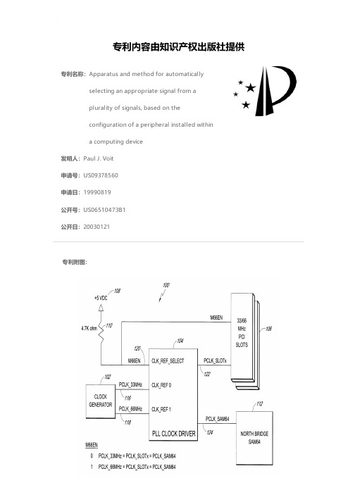
专利名称:Apparatus and method for automatically selecting an appropriate signal from aplurality of signals, based on theconfiguration of a peripheral installed withina computing device发明人:Paul J. Voit申请号:US09378560申请日:19990819公开号:US06510473B1公开日:20030121专利内容由知识产权出版社提供专利附图:摘要:An improved computer clock circuit capable of automatically detecting the internal clock frequency of a peripheral component installed in a peripheral component interconnect (PCI) slot, and supplying the PCI slot with the a clock signal of a specified frequency. In one embodiment, the clock circuit comprises a reference clock generator having multiple clock frequencies, a phaselocked loop (PLL) based clock driver, and circuitry providing the clock driver with a selection signal indicative of the configuration of a component connected within a PCI slot. The PLL clock driver maintains phase coherency between the input and output signals, thereby reducing setup and hold times within the system and peripheral components. Additionally, the PLL clock driver reduces propagation delays within the clock circuitry, and greatly simplifies implementation of the clock circuit within a given design. In another embodiment of the invention, the clock driver is also used to generate clock signals having a predetermined relationship to those produced by the reference generator, in addition to the clock signal supplied to the PCI slot. A method of automatically selecting and providing a desired clock frequency to a PCI slot is also disclosed.申请人:MICRON TECHNOLOGY, INC.代理机构:Knobbe Martens Olson & Bear LLP更多信息请下载全文后查看。
Title:CALIBRATING METHOD FOR ELECTRONIC COMPASS Electronic compass is an electronic compass by measuring the Earth's magnetic field to achieve directional navigation device, it is an important navigational tool that can provide real-time data objects heading and attitude, and has a small size, low cost, fast response , no accumulated error, etc., are widely used in mobile robots, vehicles, aircraft and other orientation subsystem; However, due to the electronic compass is based on magnetic principles calculations magnetic bearings, their work environment, in addition to other external magnetic field Earth's magnetic field will inevitably affect the output of the electronic compass, resulting in errors affect measurement accuracy. Therefore, how to reduce outside interference precision of its output is engineering applications must be addressed.Electronic compass the existing literature has proposed several possible compass error compensation method. Yuen Chee Wing paper, "three-axis magnetic heading sensors full attitude error compensation 'proposed compass error into quadrature error, zero and sensitivity errors were compensated, high compensation accuracy of the method, but in the compensation process requires non-magnetic turntable , but also the computer automatically when the measured rotation compass X and Y-axis sensor output maximum, minimum, the calibration process is complex and requires high equipment; HIGHW AY AND TRANSPORTA TION Wang Jiaxin paper "Development of high-precision electronic compass" and Shao Tingting, ROCKETS paper "electronic compass tilt and Luo slip compensation algorithm research," the least square method to compensate for the electronic compass, the method requires Compass 0 ° ~ 360 ° rotation average sampling, operation is relatively cumbersome and The amount of data samples of different sizes will have a greater impact fitting result, the amount of data is too small, the compensation effect is not good, too much data can cause performance degradation fitting; Yangxin Yong, Huang Shengguo paper "magnetic heading measurement system Error Correction Method "and Qi Zhang, Liang-shui Lei, Jiang Fan, Song Liu's paper" Autocalibration of a magnetic compasswithout heading reference "error ellipse hypothesis is proposed based on the model compensation method, because only a hypothetical model ellipse based on the experimental experience suggested that the lack of theoretical deduction, the compensation effect is not very satisfactory; Chao Min, Jiang Oriental, Wen rainbow paper, "magnetic compass error analysis and calibration" using an analytical method to establish the direction of the magnetic measurement system is more accuratemodels, and electronic compass compensation in the horizontal conditions, but the compensation process to identify more parameters (up 9), and the results show the compensation effect is similar to oval hypothetical model; Hao Zhenhai, Huang Shengguo paper, "based on a combination of differential magnetic compass heading system." proposed a "differential magnetic compass" (DMC, Differential Magnetic Compasses) design program, which uses two identical magnetic compass to determine whether the system is a combination of low-frequency interference occurs, if the system glitches did not happen, then the use of magnetic compass navigation, low-frequency interference will occur if the system switches to the gyroscope system navigation. The program does not substantially improve the magnetic compass measurement accuracy, and the navigation program consists of a plurality of magnetic compass and gyroscope structure, will lead to greatly increase the cost; Lu Wang, Zhao Zhong and other paper "Magnetic Compass Error Analysis and Compensation" using BP neural network error model, and use LM learning algorithm to train the network, the method need not 0 ° ~ 360 ° within the average sampling, with a neural network can be approximated function with arbitrary precision characteristics, with high compensation accuracy, but the BP neural network convergence is slow, the right to set initial values need to be very careful, and easy to fall into local minimum.In summary, the current electronic compass calibration methods are the main method of least squares, oval assumption France, BP neural network method, etc. These methods are more cumbersome calibration procedure or the existence of the necessary instruments for demanding calibration or calibration issues such as lack of precision.It is an electronic compass by measuring the Earth's magnetic field to achieve directional navigation device, it is an important navigational tool that can provide real-time data objects heading and attitude, and has a small size, low cost, fast response , no accumulated error, etc., are widely used in mobile robots, vehicles, aircraft and other orientation subsystem; However, due to the electronic compass is based on magnetic principles calculations magnetic bearings, their work environment, in addition to other external magnetic field Earth's magnetic field will inevitably affect the output of the electronic compass, resulting in errors affect measurement accuracy. Therefore, how to reduce outside interference precision of its output is engineering applications must be addressed.In order to simplify the calibration procedure, reducing the requirements for the necessaryequipment and to improve calibration accuracy, the present invention designed an electronic compass calibration method, the calibration method based on adaptive differential evolution method and Fourier neural network (Adaptive Differential Evolution and Fourier Neural Network, ADE-FNN), by means of Fourier neural network modeling of the electronic compass error, the neural network using orthogonal Fourier series excitation function as a network, and uses adaptive differential evolution algorithm to train the network weights, get more precise The error model to compensate for the measured values of the compass, so as to improve the precision of the compass.Differential evolution method based on adaptive neural networks and Fourier electronic compass calibration methods, including access to training samples, the use of Fourier neural network (FNN) build error compensation model and the use of adaptive differential evolution algorithm (ADE) to train the neural network weight value of three parts, to achieve the specific steps are as follows:Step one, get training samples;Step two, identified neural network structure;Step three, to create an electronic compass error model and choose the training targets;Step four: According to the training sample using an improved adaptive differential evolution algorithm for training the neural network;Step Five, will optimize the neural network weights obtained values into the neural network to obtain a more accurate compensation models;Step Six, the electronic compass output measurement values into compensate for neural network input and output compensation value.The invention took into account the impact of measurement precision electronic compass, proposes a differential evolution method based on adaptive neural networks and Fourier concentration calibration method to compensate, on the one hand to simplify the calibration process, that is just the turntable rotate (no uniform rotation) electronic compass one week for training samples and the corresponding true value; hand with better results, ie, more precisely offset outside interference, improve measurement accuracy.The compensation method with neural network structure is simple, easy to implement, and can approximate nonlinear functions with arbitrary precision, and has good generalizationcapability advantages.Orthogonal Fourier function as the excitation function neural network, the nonlinear optimization problem into a linear optimization problem, which greatly improve the convergence speed, avoid falling into local minimum.Using adaptive differential evolution algorithm to train the neural network, relying on a system to avoid the initial value problem of a priori knowledge is difficult to choose; while the improved differential evolution algorithm in the initial stages of a strong global search ability, as much as possible to find the global optimum, but at a later stage there is a strong local search ability to improve convergence rate and solution accuracy; therefore the algorithm has strong global search ability, can effectively prevent premature convergence, and algorithms good stability.How Does a Digital Compass Work?An electronic compass such as the Wayfinder uses a patented magnetic sensor technology that was first developed by PNI, Inc. for the U.S. military. This technology is called " magneto-inductive" and is the largest advancement in compass technology since the fulxgate was invented 60 years ago. The magneto-inductive technology is able to electronically sense the difference in the earth's magnetic field from a disturbance caused by external elements such as ferro-magnetic materials and the magnetic field generated by automobile electrical systems. WayFinder digital compass has an embedded micro controller that subtracts the automobile magnetic field (the distortion) from the stronger earth magnetic fields resulting in a highly accurate compass reading.Compass InstallationThe performance of a compass will greatly depend on its installation location. A compass relies on the earth’s magnetic field to provide heading. Any distortions of earth magnetic field by other sources such as a car massive iron components should be compensated for in order to determine an accurate heading. Sources of magnetic fields in any automobile include permanent magnets mostly in its audio speakers, motors, electric currents flowing in its wiring—either dc or ac, and ferro-magnetic metals such as steel or iron. The influence of these sources of interference on an electronic compass accuracy can be greatly reduced by placing the compass far away from them. Some of the field effects can be compensated by way of calibrating the compass for a definedlocation in terms of magnetic interference. However, it is not always possible to compensate for time varying magnetic fields; for example, disturbances generated by the motion of magnetic metals, or unpredictable electrical current in a nearby power lines. Magnetic shielding can be used for large field disturbances from motors or audio speakers. The best way to reduce disturbances is distance. Also, never enclose the compass in a magnetically shielded metallic housing. Compass Tilt ErrorsHeading errors due to a tilt depend somewhat on geographic location. At the equator, tilt errors are less critical since the earth's field is strictly in the horizontal plane. This provides larger X and Y readings and little of the Z component correction near the magnetic poles, tilt errors are extremely important—since there is less X,Y field and more of the Z component. Tilt errors are also dependent on the heading.Magnetic Field DistortionsNearby Ferrous materials is another consideration for heading inaccuracy. Since heading is based on the direction of the earth's horizontal field a digital compass must be able to measure this field with lesser influence from other nearby magnetic sources or disturbances.The amount of disturbance depends on the material content of the platform and connectors as well as ferrous objects moving nearby. When a ferrous object is placed in a uniform magnetic field it will exert an influence. This object could be a steel bolt or bracket near the compass or an iron door latch close to the compass. The net result is a characteristic distortion, or anomaly to the earth’s magnetic field that is unique to the shape of the object.Magnetic distortions can be categorized as two types—hard iron and soft iron effects. Hard iron distortions arise from permanent magnets and magnetized iron or steel on the compass platform. These distortions will remain constant and in a fixed location relative to the compass for all heading orientations. Hard iron effects add a constant magnitude field component along each axes of the sensor output.To compensate for hard iron distortion is usually done by rotating the compass and platform (your car) in a circle and measure enough points on the circle to determine this offset. Once found, the (X,Y) offset can be stored in memory and subtracted from every reading. The net result will be to eliminate the hard iron disturbance from the heading calculation.The soft iron distortion arises from the interaction of the earth’s magnetic field and anymagnetically soft material surrounding the compass. Like the hard iron materials, the soft metals also distort the earth’s magnetic field lines. The difference is the amount of distortion from the soft iron depends on the compass orientation.What Is True North?It is well known that the earth's magnetic poles and its axis of rotation are not at the same geographical location. They are about 11.5°rotation from each other. This creates a difference between the true north, or grid north, and the magnetic north, or direction a magnetic compass will point. Simply it is the angular difference between the magnetic and true north expressed as an Easterly or Westerly variation. This difference is defined as the variation angle and is dependent on the compass short duration, making a magnetic compass a useful navigation tool.Compass CalibrationEach calibration method is associated with a specified physical movement of the compass platform in order to sample the magnetic space surrounding the compass. The Hard and Soft iron distortions will vary from location to location within the same platform. The compass has to be mounted permanently to its platform to get a valid calibration.A particular calibration is only valid for that location of the compass. If the compass is re-oriented in the same location, then a new calibration is required. It is possible to use a compass without any calibration if the need is only for repeatability and not accuracy.题目:校准电子罗盘的方法电子罗盘是一种通过测量地球磁场来实现定向导航功能的装置,它是一种重要的导航工具,能实时提供物体的航向和姿态数据,且具有体积小、成本低、响应速度快、无累积误差等特点,被广泛应用于移动机器人、车辆、飞行器等的定向子系统中;然而,由于电子罗盘是根据地磁原理计算磁方向角,其工作环境中除地球磁场的其他外界磁场不可避免的会对电子罗盘的输出造成影响,从而产生误差影响测量精度。
专利名称:Apparatus and method for frequency channel selection in a radiotelephonesystem发明人:Roy T. Hamaoki申请号:US05/926985申请日:19780721公开号:US04166927A公开日:19790904专利内容由知识产权出版社提供摘要:In a mobile radiotelephone system, N separate modulated carrier signals in N frequency channels are applied to a demodulating radio receiver which provides a succession of N different output signals each having idle and busy states. An idle and signal-to-noise detector monitors each of the output signals of the radio receiver. The detector provides a first logic signal when one of the output signals concurrently exhibits an idle state and has at least a predetermined minimum signal-to- noise level, and provides a second logic signal at all other times. A receiver switching circuit, in response to the second logic signal, causes the receiver to cyclically switch to each of the N frequency channels. When the receiver switches to a carrier signal which causes the detector to produce a first logic signal, the switching circuit causes the receiver to lock onto that particular carrier signal. Improved operation results from a gain control circuit which reduces the gain sensitivity of the receiver upon a change in state of the detector output signal from a first logic signal to a second logic signal. The gain sensitivity is then slowly increased as the receiver cyclically switches to each of the N frequency channels. When an idle receiver output signal is detected having at least the minimum level ofsignal-to-noise, the receiver switching circuit locks the receiver onto the particular carrier signal. This technique assures that the first such detected signal will provide the best frequency channel for the demodulating radio receiver.申请人:BRITISH COLUMBIA TELEPHONE CO代理人:Douglas M. Gilbert更多信息请下载全文后查看。

FRAX 101Sweep Frequency Response AnalyzerISmallest and most rugged FRA instrument in the industryIHighest possible repeatability by using reliable cable practice and high-performance instrumentation IFulfills all international standards for SFRA measurementsIHighest dynamic range and accuracy in the industryIWireless communication and battery operatedIAdvanced analysis and decision support built into the softwareIImports data from other FRA test setsFRAX 101Sweep Frequency Response AnalyzerDESCRIPTIONPower transformers are some of the most vital components in today’s transmission and distribution infrastructure.Transformer failures cost enormous amounts of money in unexpected outages and unscheduled maintenance. It is important to avoid these failures and make testing and diagnostics reliable and efficient.The FRAX 101 Sweep Frequency Response Analyzer (SFRA) detects potential mechanical and electricalproblems that other methods are unable to detect. Major utilities and service companies have used the FRA method for more than a decade. The measurement is easy to perform and will capture a unique “fingerprint” of the transformer. The measurement is compared to a reference “fingerprint” and gives a direct answer if the mechanical parts of the transformer are unchanged or not. Deviations indicate geometrical and/or electrical changes within the transformer.FRAX 101 detects problems such as:I Winding deformations and displacements I Shorted turns and open windings I Loosened clamping structures I Broken clamping structures I Core connection problems I Partial winding collapse I Faulty core grounds I Core movements IHoop bucklingAPPLICATIONPower transformers are specified to withstand mechanical forces from both transportation and in-service events, such as faults and lightning. However, mechanical forces may exceed specified limits during severe incidents or when the insulation’s mechanical strength has weakened due to aging. A relatively quick test where the fingerprintresponse is compared to a post event response allows for a reliable decision on whether the transformer safely can be put back into service or if further diagnostics is required.Collecting fingerprint data using Frequency Response Analysis (FRA) is an easy way to detect electro-mechanical problems in power transformers and an investment that will save time and money.1981Method BasicsA transformer consists of multiple capacitances,inductances and resistors, a very complex circuit that generates a unique fingerprint or signature when test signals are injected at discrete frequencies and responses are plotted as a curve.Capacitance is affected by the distance betweenconductors. Movements in the winding will consequently affect capacitances and change the shape of the curve.The SFRA method is based on comparisons between measured curves where variations are detected. One SFRA test consists of multiple sweeps and reveals if the transformer’s mechanical or electrical integrity has been jeopardized.Practical Application In its standard application, a “finger print” reference curvefor each winding is captured when the transformer is new or when it is in a known good condition. These curves can later be used as reference during maintenance tests or when there is reason to suspect a problem.The most reliable method is the time based comparison where curves are compared over time on measurements from the same transformer. Another method utilizes type based comparisons between “sister transformers” with the same design. Lastly, a construction based comparison can,under certain conditions, be used when comparingmeasurements between windings in the same transformer.These comparative tests can be performed 1) before and after transportation, 2) after severe through faults 3) before and after overhaul and 4) as diagnostic test if you suspect potential problems. One SFRA test can detect windingproblems that requires multiple tests with different kinds of test equipment or problems that cannot be detected with other techniques at all. The SFRA test presents a quick and cost effective way to assess if damages have occurred or if the transformer can safely be energized again. If there is a problem, the test result provides valuable information that can be used as decision support when determining further action.Having a reference measurement on a mission critical transformer when an incident has occurred is, therefore, a valuable investment as it will allow for an easier and more reliable analysis.Analysis and SoftwareAs a general guideline, shorted turns, magnetization and other problems related to the core alter the shape of the curve in the lowest frequencies. Medium frequencies represent axial or radial movements in the windings and high frequencies indicate problems involving the cables from the windings, to bushings and tap changers.FRAX 101Sweep Frequency Response AnalyzerAn example of low,medium and high frequenciesThe figure above shows a single phase transformer after a serviceoverhaul where, by mistake, the core ground never got connected (red),and after the core ground was properly connected (green). This potential problem clearly showed up at frequencies between 1 kHz and 10 kHz and a noticeable change is also visible in the 10 kHz - 200 kHz range.The FRAX Software provides numerous features to allow for efficient data analysis. Unlimited tests can be open at the same time and the user has full control on which sweeps to compare. The response can be viewed in traditional Magnitude vs. Frequency and/or Phase vs.Frequency view. The user can also choose to present the data in an Impedance or Admittance vs. Frequency view for powerful analysis on certain transformer types.FRAX 101Sweep Frequency Response AnalyzerTest Object Browser —Unlimited number of tests and sweeps. Full user control.Quick Select Tabs —Quickly change presentation view for differentperspectives and analysis tools.Quick Graph Buttons —Programmablegraph setting lets you change views quickly and easily.Sweep/Curve Settings —Every sweep can be individually turned on or off,change color,thickness and position.Dynamic Zoom —Zoom in and move your focus to any part of the curve.Operation Buttons —All essentialfunctions at your fingertips; select with mouse, function keys or touch screen.Automated analysis compares two curves using an algorithm that compare amplitude as well asfrequency shift and lets you know if the difference is severe, obvious, or light.Built-in-decision support is provided by using a built-inanalysis tool based on the international standard DL/T 911-2004.FRAX 101Sweep Frequency Response AnalyzerConsiderations When Performing SFRA MeasurementsSFRA measurements are compared over time or between different test objects. This accentuates the need to perform the test with the highest repeatability and eliminates the influence from external parameters such as cables,connections and instrument performance. FRAX offers all the necessary tools to ensure that the measured curve represents the internal condition of the transformer.Good Connections Bad connections cancompromise the test results which is why FRAX offers a rugged test clamp thatensures good connection to the bushings and solid connections to the instrument.Shortest Braid ConceptThe connection from the cable shield to ground has to be the same for every measurement on a given transformer.Traditional ground connections techniques have issues when it comes to providing repeatable conditions. This causes unwanted variations in the measured response for the highest frequencies that makes analysis difficult. The FRAX braid drops down from the connection clamp next to the insulating discs to the ground connection at the base of the bushing. This creates near identicalconditions every time you connect to a bushing whether it is tall or short.The Power of WirelessFRAX 101 uses class 1 Bluetooth ®wireless communication.Class 1 Bluetooth ®has up to 100 m range and is designed for industrial applications. An optional internal battery pack is available for full wireless flexibility. Shorter and more light-weight cables can be used when the user is liberated from cable communication and power supply cables.A standard USB interface (galvanically isolated) is included for users who prefer a direct connection to their PC. IMPORT AND EXPORTThe FRAX software can import data files from other FRA instruments making it possible to compare data obtained using another FRA unit. FRAX can import and export data according to the international XFRA standard format as well as standard CSV and TXT formats.Optimized Sweep SettingThe software offers the user an unmatched feature that allows for fast and efficient testing. Traditional SFRAsystems use a logarithmic spacing of measurement points.This results in as many test points between 20Hz and200Hz as between 200KHz and 2MHz and a relatively long measurement time.The frequency response from the transformer contains a few resonances in the low frequency range but a lot of resonances at higher frequencies. FRAX allows the user to specify less measurement points at lower frequencies and high measurement point density at higher frequencies.The result is a much faster sweep with greater detail where it is needed.Variable VoltageThe applied test voltage may affect the response at lower frequencies. Some FRA instruments do not use the 10 V peak-to-peak used by major manufacturers and this may complicate comparisons between tests. FRAX standard voltage is 10 V peak-to-peak but FRAX also allows the user to adjust the applied voltage to match the voltage used in a different test.FTB 101Several international FRA guides recommends to verify the integrity of cables and instrument before and after a test using a test circuit with a known FRA response supplied by the equipment manufacturer. FRAX comes with a field test box FTB101 as a standard accessory and allows the user to perform this important validation in the field at any time and secure measurement quality.The laptop can be operated by touch screen and the communication is wireless via Bluetooth. Measurement ground braids connect close to the connection clamps and run next to the bushing to the flange connectionto avoid cable loops that otherwise affect the measurement.Contacts made with the C-clamp guarantee good connectionsFTB 101 Field Test BoxFRAX 101Sweep Frequency Response AnalyzerDYNAMIC RANGEMaking accurate measurements in a wide frequency range with high dynamics puts great demands on test equipment,test leads, and test set up. FRAX 101 is designed with these requirements in mind. It is rugged, able to filter induced interference and has the highest dynamic range andaccuracy in the industry. FRAX 101 dynamic range or noise floor is shown in red below with a normal transformer measurement in black. A wide dynamic range, low noise floor, allows for accurate measurements in everytransformer. A margin of about 20 dB from the lowest response to the instruments noise floor must be maintained to obtain ±1 dB accuracy.SPECIFICATIONSGeneral FRA Method: Sweep frequency (SFRA)Frequency Range:0.1 Hz - 25 MHz, user selectable Number of Points:Default 1046,User selectable up to 32,000Measurement time:Default 64 s, fast setting,37 s (20 Hz - 2 MHz)Points Spacing:Log., linear or both Dynamic Range/Noise Floor:>130dB Accuracy:±0.3 dB down to -105 dB(10 Hz - 10 MHz)IF Bandwidth/Integration Time:User selectable (10% default) Software:FRAX for Windows 2000/ XP/Vista PC Communication:Bluetooth and USB(galvanically isolated)Calibration Interval:Max 3 yearsStandards/guides:Fulfill requirements in CigréBrochure 342, 2008Mechanical condition assessment of transformer windings using FRA and Chinese standard DL/T 911-2004, FRA on winding deformation of powertransformers, as well as other international standards and recommendations Analog Output Channels:1Compliance Voltage:0.2 - 20 V peak-to-peak Measurement Voltage at 50 Ω:0.1 - 10 V peak-to-peak Output Impedance:50 ΩProtection:Short-circuit protected Analog Input Channels: 2Sampling:Simultaneously Input Impedance:50 ΩSampling Rate:100 MS/sPhysicalInstrument Weight:1.4 kg/3.1 lbs Case and Accessories Weight:15 kg/33 lbsDimensions:250 x 169 x 52 mm 9.84 x 6.65 x 2.05 in Dimensions with Case:520 x 460 x 220 mm 20.5 x 18.1 x 8.7 in.Input Voltage:11 - 16 V dc or 90 - 135 V ac and 170 - 264V ac, 47-63 Hz EnvironmentalOperating Ambient Temp: -20°C to +50°C /-4°F to +122°F Operating Relative Humidity:< 90% non-condensingStorage Ambient Temp:-20°C to 70°C / -4°F to +158°F Storage Relative Humidity:< 90% non-condensingCE Standards:IEC61010 (LVD) EN61326 (EMC)PC Requirements (PC not included)Operating System:Windows 2000/ XP / Vista Processor:Pentium 500 MHz Memory:256 Mb RAM or more Hard Drive:Minimum 30 Mb free Interface:Wireless or USB (client)An example of FRAX 101’s dynamic limit (red) and transformer measurement (black)FEATURES AND BENEFITSI Smallest and most rugged FRA instrument in the industry.IGuaranteed repeatability by using superior cablingtechnology, thus avoiding the introduction of error due to cable connection and positioning (which is common in other FRA manufacturers’ equipment).IFulfills all international standards for Sweep Frequency Response Analysis (SFRA) measurements.IHighest dynamic range and accuracy in the industry allowing even the most subtle electro-mechanical changes within the transformer to be detected.IWireless communication allows easy operation without the inconvenience of cable hook up to a PC.IBattery input capability allows for easy operation without the need for mains voltage supply.IAdvanced analysis and support software tools allows for sound decision making with regard to further diagnostics analysis and/or transformer disposition.FRAX 101Sweep Frequency Response AnalyzerUKArchcliffe Road, Dover CT17 9EN EnglandT +44 (0) 1 304 502101 F +44 (0) 1 304 207342******************UNITED STATES 4271 Bronze WayDallas, TX 75237-1019 USA T 1800 723 2861 (USA only) T +1 214 333 3201 F +1 214 331 7399******************Registered to ISO 9001:2000 Cert. no. 10006.01FRAX101_DS_en_V01Megger is a registered trademark Specifications are subject to change without notice.OTHER TECHNICAL SALES OFFICES Täby SWEDEN, Norristown USA,Sydney AUSTRALIA, Toronto CANADA,Trappes FRANCE, Kingdom of BAHRAIN,Mumbai INDIA, Johannesburg SOUTH AFRICA, and Chonburi THAILANDFRAX cable set consists of double shielded high quality cables, braid for easy and reliable ground connection, and clamp for solid connections to the test object.OPTIONAL ACCESSORIESI The built-in battery pack offers flexibility when performing tests on or off the transformer.IThe Active Impedance Probe AIP 101 should be used when measuring grounded connections such as to the transformer tank or a bushing connected to thetransformer tank. AIP 101 ensures safe, accurate and easy measurements to ground.IThe Active Voltage Probe AVP 101 is designed formeasurements when higher input impedance is needed.AVP 101 can be used for measurements where up to 1M Ωinput impedance is required.Item (Qty)Cat. No.Optional Accessories Battery option, 4.8 Ah AC-90010Calibration setAC-90020 Active impedance probe AIP 101AC-90030Active voltage probe AVP 101AC-90040FRAX Demo box FDB 101AC-90050Field Demo Box FTB 101AC-90060Ground braid set, 4 x 3 m including clamps GC-30031FRAX Generator cable, 2xBNC, 9 m (30 ft)GC-30040FRAX Generator cable, 2xBNC, 18 m (59 ft)GC-30042FRAX Measure cable, 1xBNC, 9 m (30 ft)GC-30050FRAX Measure cable, 2xBNC, 18 m (59 ft)GC-30052FRAX C-clamp GC-80010FRAX for WindowsSA-AC101Item (Qty)Cat. No.FRAX 101complete with: ac/dc adapter,mains cable,ground cable 5 m (16 ft), transport case,USB cable, Bluetooth adapter, Windows software, 4x 3m (10 ft) ground braid set, 2 x C-clamp, field test box, generator cable 18 m (59 ft), measure cable 18 m (59 ft), manual AC-19090FRAX 101, incl. battery,complete with: ac/dc adapter,mains cable,ground cable 5 m (16 ft), transport case,USB cable, Bluetooth adapter,Windows software, 4x 3m (10 ft) ground braid set, 2 x C-clamp, field test box, generator cable 18 m (59 ft), measure cable 18 m (59 ft), battery pack, manual AC-19091ORDERING INFORMATION。
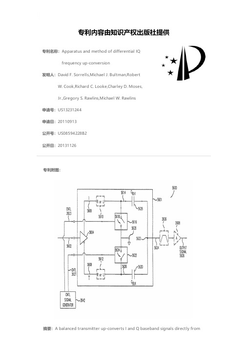
专利名称:Apparatus and method of differential IQfrequency up-conversion发明人:David F. Sorrells,Michael J. Bultman,RobertW. Cook,Richard C. Looke,Charley D. Moses,Jr.,Gregory S. Rawlins,Michael W. Rawlins申请号:US13231244申请日:20110913公开号:US08594228B2公开日:20131126专利内容由知识产权出版社提供专利附图:摘要:A balanced transmitter up-converts I and Q baseband signals directly frombaseband-to-RF. The up-conversion process is sufficiently linear that no IF processing is required, even in communications applications that have stringent requirements on spectral growth. In operation, the balanced modulator sub-harmonically samples the I and Q baseband signals in a balanced and differential manner, resulting in harmonically rich signal. The harmonically rich signal contains multiple harmonic images that repeat at multiples of the sampling frequency, where each harmonic contains necessary information to reconstruct the I and Q baseband signals. The differential sampling is performed according to control signals that are phase shifted with respect to each other. The control signals may have pulse widths (or apertures) that operate to improve energy transfer to a desired harmonic in the harmonically rich signal. A bandpass filter can then be utilized to select the desired harmonic of interest from the harmonically rich signal.申请人:David F. Sorrells,Michael J. Bultman,Robert W. Cook,Richard C. Looke,Charley D. Moses, Jr.,Gregory S. Rawlins,Michael W. Rawlins地址:Middleburg FL US,Jacksonville FL US,Switzerland FL US,Jacksonville FLUS,DeBary FL US,Heathrow FL US,Lake Mary FL US国籍:US,US,US,US,US,US,US代理机构:Workman Nydegger更多信息请下载全文后查看。

专利名称:RADIO-FREQUENCY CHANNEL CORRECTINGMETHOD AND APPARATUS, ANTENNA, ANDBASE STATION发明人:XIAO, Weihong,WANG, Linlin,GONG,Lanping,CHEN, Lei申请号:EP20747743.1申请日:20200116公开号:EP3905552A1公开日:20211103专利内容由知识产权出版社提供专利附图:摘要:This application provides a radio frequency channel calibration method andapparatus, an antenna, and a base station. The antenna includes: at least three radio frequency interfaces and a feed network disposed among the at least three radio frequency interfaces, where each of the at least three radio frequency interfaces is connected to one radio frequency channel between the radio frequency interface and a remote radio unit RRU. A first interface is configured to receive a signal from the RRU, and transmit the signal to a second interface by using the feed network. The second interface is configured to send the signal to the RRU. The feed network includes a main feed circuit, a calibration signal circuit, and a switch. The calibration signal circuit is configured to transmit a calibration signal from the first interface to the second interface, where the calibration signal is used to calibrate a phase and an amplitude of the radio frequency channel connected to the first interface. The switch is configured to isolate the calibration signal from a signal on the main feed circuit. In this application, interference of the signal on the main feed circuit to the calibration signal can be reduced, correctness of a calibration result can be ensured, and various RRU devices can be compatible with.申请人:Huawei Technologies Co., Ltd.地址:Huawei Administration Building, Bantian, Longgang District, Shenzhen, Guangdong 518129, CN国籍:CN代理机构:Thun, Clemens更多信息请下载全文后查看。
专利名称:Apparatus and Method of Differential IQFrequency Up-Conversion发明人:David F. Sorrells,Michael J. Bultman,RobertW. Cook,Richard C. Looke,Charley D. Moses,JR.,Gregory S. Rawlins,Michael W. Rawlins申请号:US14081501申请日:20131115公开号:US20140233670A1公开日:20140821专利内容由知识产权出版社提供专利附图:摘要:A balanced transmitter up-converts I and Q baseband signals directly frombaseband-to-RF. The up-conversion process is sufficiently linear that no IF processing is required, even in communications applications that have stringent requirements on spectral growth. In operation, the balanced modulator sub-harmonically samples the I and Q baseband signals in a balanced and differential manner, resulting in harmonically rich signal. The harmonically rich signal contains multiple harmonic images that repeat at multiples of the sampling frequency, where each harmonic contains the necessary information to reconstruct the I and Q baseband signals. The differential sampling is performed according to a first and second control signals that are phase shifted with respect to each other. In embodiments of the invention, the control signals have pulse widths (or apertures) that operate to improve energy transfer to a desired harmonic in the harmonically rich signal. A bandpass filter can then be utilized to select the desired harmonic of interest from the harmonically rich signal.申请人:ParkerVision, Inc.地址:Jacksonville FL US国籍:US更多信息请下载全文后查看。
专利名称:Real-time improvement method andapparatus for distributed network radiofrequency performance发明人:Xiaojian Tang,Bojing Yang申请号:US13878679申请日:20110616公开号:US09288775B2公开日:20160315专利内容由知识产权出版社提供专利附图:摘要:A real-time improvement method and a real-time improvement apparatus for a distributed network radio frequency performance are provided by the present invention.The method comprises: a data analysis unit receiving an input power, an output power and a link gain from a base station element node with a radio frequency module, and establishing a learning model of the base station element node according to the input power, the output power and the link gain; the data analysis unit obtaining an expected output power corresponding to the input power according to a correlation between a preset input power and the expected output power; in the learning model, regulating the link gain according to a difference value between the expected output power and the output power, until the difference value between the output power of the learning model and the expected output power reaches a preset range, and determining the link gain at this moment as a new link gain; and the data analysis unit sending the new link gain to the base station element node with a radio frequency module, and the base station element node regulating the link gain thereof according to the new link gain.申请人:Xiaojian Tang,Bojing Yang地址:Guangdong Province CN,Guangdong Province CN国籍:CN,CN代理机构:Holland & Knight LLP代理人:Brian J. Colandreo,Michael T. Abramson更多信息请下载全文后查看。
专利名称:Apparatus and method for detecting andcompensating for resonance frequency indata storage system发明人:Da-woon Chung申请号:US10972562申请日:20041026公开号:US07031094B2公开日:20060418专利内容由知识产权出版社提供专利附图:摘要:A method and an apparatus detect and compensate for a mechanical resonance frequency occurring in a system. The apparatus includes an excitation unit that increases again of a predetermined frequency band of a driving signal, a resonance frequency detector frequency-transforming a response signal, and detecting the resonance frequency in a frequency domain, an excitation signal generator separately generating a first excitation signal and a second excitation signal, a mixer mixing one of the first excitation signal or the second excitation signal with a driving signal that does not pass through the excitation unit, and inputting a result of the combination to the system, a resonance determination unit determining whether resonance occurs in the system, and a system controller determining a frequency of one of the first excitation signal or the second excitation signal input when resonance occurs in the system, as the resonance frequency.申请人:Da-woon Chung地址:Suwon-si KR国籍:KR代理机构:Staas & Halsey LLP更多信息请下载全文后查看。
专利名称:Apparatus and method of updating filter tapcoefficients of equalizer发明人:Shim, Jae-seong,Park, Hyun-soo,Lee, Jae-wook,Lee, Jung-hyun申请号:EP03252017.3申请日:20030331公开号:EP1365402A2公开日:20031126专利内容由知识产权出版社提供专利附图:摘要:An apparatus and method of updating the filter tap coefficients of an equalizer used in an optical disc recording/reproducing apparatus, and a computer readablerecording medium that stores a program for implementing the method. A filter unit (106) filters an error signal included in an input signal, which is a radio frequency (RF) signal reflected by an optical disc. A defect signal detection unit (107) detects whether the input signal is defective and outputs an update stop signal. A coefficient updating unit (111) stops updating a plurality of filter tap coefficients of the filter unit (106) in response to the update stop signal and outputs the current filter tap coefficients to the filter unit (106). By using the filter tap coefficient updating apparatus, the filter tap coefficient updating is normally performed without errors even if a defect exists on an optical disc or track jumping occurs, so that freezing or breaking of an image screen is prevented.申请人:SAMSUNG ELECTRONICS CO., LTD.地址:416, Maetan-dong, Paldal-gu Suwon-City, Kyungki-do KR国籍:KR代理机构:Robinson, Ian Michael更多信息请下载全文后查看。