CCNP之OSPF实验案例
- 格式:doc
- 大小:92.00 KB
- 文档页数:9
Single Area OSPF【实验目的】了解和掌握OSPF 的原理,熟悉OSPF 配置步骤。
懂得如何配置OSPF router ID ,update timers, authentication,了解DR/BDR 选举过程,以及在multi-access 网络和帧中继网络上点到多点的OSPF 配置。
【基本概念及实验原理】 OSPF 数据包的五种类型:Type 1- Hello 用于建立和维持与邻居的连接信息Type 2- Database description packet(DBD) 用于描述一个路由器的链路状态数据库的内容Type 3- Link-state request(LSR) 用于请求一个路由器链路状态数据库的一些特定的条目Type 4- Link-state update(LSU) 用于把“链路状态更新”(LSAs)传输给其它路由器Type 5- Link-state acknowledgment (LSAck) 用于确认自己收到了一个从邻居发过来的LSAOSPF 的各种状态(OSPF 邻居关系建立的过程)Down.Æ Init. Æ Two-Way. Æ ExStart. Æ Exchange. Æ Loading. Æ Full Adjacencyhello Æ 发现邻居Æ确定主从关系Æ比较数据库Æ交换数据Æ确立邻接关系Designated Router (DR) / Backup Designated Router(BDR)选举过程(存在于multiaccess 网络,点对点和点对多点网络中无此选举过程)选举过程:依次比较hello 包中的端口优先级(priority),路由id 。
选举结束后,只有DR/BDR fail 才会引起新的选举过程;如果发生DR 故障,则BDR 替补上去;次高优先级router 选为BDR 。
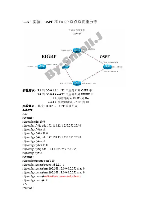
CCNP实验:OSPF和EIGRP双点双向重分布实验需求:R1的LO 0 1.1.1.1/32口重分布到OSPF中R4的LO 0 4.4.4.4/32口重分布到EIGRP中1.1.1.1负载均衡从R2 R3到R44.4.4.4 负载均衡从R2 R3到R1实验要点:修改EIGRP 、OSPF管理距离基本配置R1:r1#conf tr1(config)#int f0/0r1(config-if)#ip add 192.168.12.1 255.255.255.0r1(config-if)#no shr1(config-if)#int f1/0r1(config-if)#ip add 192.168.13.1 255.255.255.0r1(config-if)#no shr1(config-if)#int lo 0r1(config-if)#ip add 1.1.1.1 255.255.255.255r1(config-if)#^Zr1#conf tr1(config)#router ospf 110r1(config-router)#router-id 1.1.1.1r1(config-router)#net 192.168.12.0 0.0.0.255 area 0r1(config-router)#net 192.168.13.0 0.0.0.255 area 0r1(config-router)#redistribute connected subnetsr1(config-router)#^ZR2:r2#conf tr2(config-if)#ip add 192.168.12.2 255.255.255.0r2(config-if)#no shr2(config-if)#int f1/0r2(config-if)#ip add 192.1.1.2 255.255.255.0r2(config-if)#no shr2(config-if)#z^r2#conf tr2(config)#router ospf 110r2(config-router)#router-id 2.2.2.2r2(config-router)#net 192.168.12.0 0.0.0.255 area 0r2(config-router)#redistribute eigrp 100 subnetsr2(config-router)#^Zr2#conf tr2(config)#router eigrp 100r2(config-router)#net 192.1.1.0r2(config-router)#redistribute ospf 110 metric 1000 100 255 1 1500 r2(config-router)#^ZR3:r3#conf tr3(config)#int f0/0r3(config-if)#ip add 192.168.13.3 255.255.255.0r3(config-if)#no shr3(config-if)#int f1/0r3(config-if)#ip add 192.1.1.3 255.255.255.0r3(config-if)#no shr3(config-if)#^Zr3#conf tr3(config)#router ospf 110r3(config-router)#router-id 3.3.3.3r3(config-router)#net 192.168.13.0 0.0.0.255 area 0r3(config-router)#redistribute eigrp 100 subnetsr3(config-router)#^Zr3#conf tr3(config)#router eigrp 100r3(config-router)#net 192.1.1.0r3(config-router)#redistribute ospf 110 metric 1000 100 255 1 1500 r3(config-router)#^ZR4:r4#conf tr4(config)#int f0/0r4(config-if)#ip add 192.1.1.4 255.255.255.0r4(config-if)#no shr4(config-if)#ip add 4.4.4.4 255.255.255.255r4(config-if)#^Zr4#conf tr4(config)#router eigrp 100r4(config-router)#net 192.1.1.0r4(config-router)#redistribute connected metric 1000 100 255 1 1500r4(config-router)#^Z解决需求方案:修改OSPF管理距离R2:r2#conf tr2(config)#router ospf 110r2(config-router)#distance 180 3.3.3.3 0.0.0.0r2(config-router)#^ZR3:r3#conf tr3(config)#router ospf 110r3(config-router)#distance 180 2.2.2.2 0.0.0.0r3(config-router)#^Z实验结果测试:r1#show ip routeC 192.168.12.0/24 is directly connected, FastEthernet0/01.0.0.0/32 is subnetted, 1 subnetsC 1.1.1.1 is directly connected, Loopback0C 192.168.13.0/24 is directly connected, FastEthernet1/04.0.0.0/32 is subnetted, 1 subnetsO E2 4.4.4.4 [110/20] via 192.168.13.3, 00:40:15, FastEthernet1/0[110/20] via 192.168.12.2, 00:40:15, FastEthernet0/0O E2 192.1.1.0/24 [110/20] via 192.168.13.3, 00:41:55, FastEthernet1/0[110/20] via 192.168.12.2, 00:41:55, FastEthernet0/0r2# r3# r4#show ip route实验结论:通过修改OSPF通过指定路由器的管理距离,解决负载均衡双点双向重分布。
实验六:单区域OSPF配置⏹实验目的1、在路由器上启动OSPF路由进程2、启用参与路由协议的接口,并且通告网络及其所在的区域3、路由id的配置4、DR选举的控制5、OSPF的MD5认证6、查看和调试OSPF路由协议和MD5相关信息⏹实验要求本实验要达到如下要求:1、给出具体的实现步骤2、给出某个路由器上路由表的内容3、给出认证的调试信息4、给出各个网段的DR和BDR⏹实验设备(环境、软件)1、路由器3台2、交叉线3条3、光纤1条⏹实验设计到的基本概念和理论给出OSPF特性、链路、链路状态、自治系统、区域的概念⏹在路由器上启动OSPF路由进程Router(config)#router ospf 0Router(config-router)#network 192.168.1.0 0.0.0.255 area 2其他路由器采用相同操作路由id的配置DR选举的控制Router(config)#int f6/0Router(config-if)#ip ospf priority 10OSPF的MD5认证Router(config-if)#ip ospf message-digest-key 20 md5 12345查看和调试OSPF路由协议和MD5相关信息开启debugRouter#debug ip ospf adjRouter#debug ip ospf events查看debugRouter#show debugtion type. Input packet specified type 2, we use type 001:50:58: OSPF: Rcv hello from 1.0.1.2 area 0 from FastEthernet0/0 192.168.2.2001:50:58: OSPF: End of hello processingOSPF events debugging is onRouter#01:51:07: OSPF: Rcv pkt from 192.168.1.1, FastEthernet1/0 : Mismatch Authentication type. Input packet specified type 2, we use type 001:51:08: OSPF: Rcv hello from 1.0.1.2 area 0 from FastEthernet0/0 192.168.2.20终于弄明白了MD5认证具体怎么用。

【CCNP】帧中继环境下OSPF ⽹络类型BROADCAST【CCNP】帧中继环境下OSPF ⽹络类型BROADCAST修订记录修订⽇期修订⼈版本号审核⼈修订说明2012-09-13Jeff 1.0Jeff正式发布1案例配置拓扑2案例配置需求1、配置HUB&SPOKE模型的帧中继⽹络,R1为HUB,采⽤静态映射的⽅式;2、IP地址规划⽅⾯,R1/R2/R3上有⼀环回接⼝loopback 0,地址为X.X.X.X/32(其中X为路由器编号,如R1的环回⼝loopback 0地址为1.1.1.1/32),帧中继⽹络的地址为172.8.100.X/24(其中X为路由器编号,如R1的帧中继接⼝地址为172.8.100.1/24)3、配置R1/R2/R3所有的接⼝network到OSPF区域0,进程号为100;4、修改帧中继接⼝的OSPF⽹络类型为BROADCAST;5、实现R1/R2/R3的loopback 0接⼝互通;3案例配置思路1、配置R1/R2/R3帧中继接⼝:R1interface Serial0/0encapsulation frame-relayno frame-relay inverse-arp /关闭inverse-arp,采⽤静态映射的⽅式/ip address 172.8.100.1 255.255.255.0frame-relay map ip 172.8.100.2 102 broadcastframe-relay map ip 172.8.100.3 103 broadcast/加上broadcast参数,让PVC具有传送⼴播或者组播的能⼒/R2interface Serial0/0encapsulation frame-relayno frame-relay inverse-arpip address 172.8.100.2 255.255.255.0frame-relay map ip 172.8.100.1 201 broadcastR3interface Serial0/0encapsulation frame-relayno frame-relay inverse-arpip address 172.8.100.3 255.255.255.0frame-relay map ip 172.8.100.1 301 broadcast2、配置R1基本的OSPF:router ospf 100router-id 1.1.1.1 /⼿动指定RID/network 1.1.1.1 0.0.0.0 area 0network 172.8.100.1 0.0.0.0 area 03、配置R2基本的OSPF:router ospf 100router-id 2.2.2.2 /⼿动指定RID/network 2.2.2.2 0.0.0.0 area 0network 172.8.100.2 0.0.0.0 area 04、配置R3基本的OSPF:router ospf 100router-id 3.3.3.3 /⼿动指定RID/network 3.3.3.3 0.0.0.0 area 0network 172.8.100.3 0.0.0.0 area 05、配置R1/R2/R3接⼝的⽹络类型为BROADCAST:R1/R2/R3interface s0/0ip ospf network broadcast /设置接⼝的⽹络类型为broadcast/6、修改R1/R2/R3帧中继OSPF接⼝优先级:R1interface s0/0ip ospf priority 255 /选举为DR/R2interface s0/0ip ospf priority 0 /不参与DR的选举/R3interface s0/0ip ospf priority 0 /不参与DR的选举/7、修正R2/R3下⼀跳不可达情况,让R2/R3到达对⽅的loopback 0接⼝的下⼀跳可达:R2interface Serial0/0frame-relay map ip 172.8.100.3 201 broadcastR3interface Serial0/0frame-relay map ip 172.8.100.2 301 broadcast4案例检验结果1、采⽤show ip ospf int s0/0查看接⼝的⽹络类型:R1#show ip ospf int s0/0Serial0/0 is up, line protocol is upInternet Address 172.8.100.1/24, Area 0Process ID 100, Router ID 1.1.1.1, Network Type BROADCAST, Cost: 64 Transmit Delay is 1 sec, State DR, Priority 255Designated Router (ID) 1.1.1.1, Interface address 172.8.100.1No backup designated router on this networkTimer intervals configured, Hello 10, Dead 40, Wait 40, Retransmit 5oob-resync timeout 40Hello due in 00:00:04Supports Link-local Signaling (LLS)Index 2/2, flood queue length 0Next 0x0(0)/0x0(0)Last flood scan length is 1, maximum is 1Last flood scan time is 0 msec, maximum is 4 msecNeighbor Count is 2, Adjacent neighbor count is 2Adjacent with neighbor 2.2.2.2Adjacent with neighbor 3.3.3.3Suppress hello for 0 neighbor(s)2、采⽤show ip ospf nei查看路由器的邻居状态:R1#show ip ospf neiNeighbor ID Pri State Dead Time Address Interface3.3.3.3 0 FULL/DROTHER 00:01:53 172.8.100.3 Serial0/02.2.2.2 0 FULL/DROTHER 00:01:31 172.8.100.2 Serial0/0/邻居的接⼝优先级为0,不参与DR的选举,⾓⾊为DROTHER/R2#show ip ospf neiNeighbor ID Pri State Dead Time Address Interface1.1.1.1 255 FULL/DR 00:01:44 172.8.100.1 Serial0/0R3#show ip ospf neiNeighbor ID Pri State Dead Time Address Interface1.1.1.1 255 FULL/DR 00:01:30 172.8.100.1 Serial0/0 3、采⽤show ip route查看路由表:R1#show ip routeCodes: C - connected, S - static, R - RIP, M - mobile, B - BGPD - EIGRP, EX - EIGRP external, O - OSPF, IA - OSPF inter areaN1 - OSPF NSSA external type 1, N2 - OSPF NSSA external type 2 E1 - OSPF external type 1, E2 - OSPF external type 2i - IS-IS, su - IS-IS summary, L1 - IS-IS level-1, L2 - IS-IS level-2ia - IS-IS inter area, * - candidate default, U - per-user static route o - ODR, P - periodic downloaded static routeGateway of last resort is not set1.0.0.0/32 is subnetted, 1 subnetsC 1.1.1.1 is directly connected, Loopback02.0.0.0/32 is subnetted, 1 subnetsO 2.2.2.2 [110/65] via 172.8.100.2, 00:51:45, Serial0/03.0.0.0/32 is subnetted, 1 subnetsO 3.3.3.3 [110/65] via 172.8.100.3, 00:51:45, Serial0/0172.8.0.0/24 is subnetted, 1 subnetsC 172.8.100.0 is directly connected, Serial0/0R2#show ip routeCodes: C - connected, S - static, R - RIP, M - mobile, B - BGPD - EIGRP, EX - EIGRP external, O - OSPF, IA - OSPF inter areaN1 - OSPF NSSA external type 1, N2 - OSPF NSSA external type 2 E1 - OSPF external type 1, E2 - OSPF external type 2i - IS-IS, su - IS-IS summary, L1 - IS-IS level-1, L2 - IS-IS level-2ia - IS-IS inter area, * - candidate default, U - per-user static route o - ODR, P - periodic downloaded static routeGateway of last resort is not set1.0.0.0/32 is subnetted, 1 subnetsO 1.1.1.1 [110/65] via 172.8.100.1, 00:55:45, Serial0/02.0.0.0/32 is subnetted, 1 subnetsC 2.2.2.2 is directly connected, Loopback03.0.0.0/32 is subnetted, 1 subnetsO 3.3.3.3 [110/65] via 172.8.100.3, 00:55:45, Serial0/0/下⼀跳为172.8.100.3,需要添加到此地址的帧中继静态映射/172.8.0.0/24 is subnetted, 1 subnetsC 172.8.100.0 is directly connected, Serial0/0R3#show ip routeCodes: C - connected, S - static, R - RIP, M - mobile, B - BGPD - EIGRP, EX - EIGRP external, O - OSPF, IA - OSPF inter areaN1 - OSPF NSSA external type 1, N2 - OSPF NSSA external type 2 E1 - OSPF external type 1, E2 - OSPF external type 2i - IS-IS, su - IS-IS summary, L1 - IS-IS level-1, L2 - IS-IS level-2ia - IS-IS inter area, * - candidate default, U - per-user static route o - ODR, P - periodic downloaded static routeGateway of last resort is not set1.0.0.0/32 is subnetted, 1 subnetsO 1.1.1.1 [110/65] via 172.8.100.1, 00:58:59, Serial0/02.0.0.0/32 is subnetted, 1 subnetsO 2.2.2.2 [110/65] via 172.8.100.2, 00:58:59, Serial0/0/下⼀跳为172.8.100.2,需要添加到此地址的帧中继静态映射/3.0.0.0/32 is subnetted, 1 subnetsC 3.3.3.3 is directly connected, Loopback0172.8.0.0/24 is subnetted, 1 subnetsC 172.8.100.0 is directly connected, Serial0/04、采⽤ping测试R2到达R3 loopback 0接⼝的下⼀跳:R2#ping 172.8.100.3Type escape sequence to abort.Sending 5, 100-byte ICMP Echos to 172.8.100.3, timeout is 2 seconds:Success rate is 100 percent (5/5), round-trip min/avg/max = 56/80/132 msR2#5、采⽤traceroute测试R2到达R3 loopback 0的路径:R2#traceroute 3.3.3.3 source lo 0Type escape sequence to abort.Tracing the route to 3.3.3.31 172.8.100.1 28 msec 52 msec 8 msec2 172.8.100.3 28 msec * 128 msec/由于是HUB&SPOKE环境,R2和R3之间没有建⽴PVC,所以R2到R3 loopback 0的数据必须⾛R1和R2之间的PVC,跟踪的路径先到R1,然后到R3/6、采⽤ping测试R2 loopback 0和R3 loopback 0的连通性:R2#ping 3.3.3.3 source lo 0Type escape sequence to abort.Sending 5, 100-byte ICMP Echos to 3.3.3.3, timeout is 2 seconds:Packet sent with a source address of 2.2.2.2Success rate is 100 percent (5/5), round-trip min/avg/max = 36/65/108 ms5案例配置⽂件(略)6案例总结及其他1、帧中继主接⼝默认的⽹络类型为NON_BROADCAST,通过修改R1/R2/R3帧中继接⼝的OSPF⽹络类型为BROADCAST,在该⽹络类型下,邻居⾃动发现,所以不需要⼿动指定邻居,由于是多路访问的环境,所以需要选举DR,⼀般推荐在HUB&SPOKE环境下HUB路由器为DR(将接⼝的OSPF优先级设置为255),其他SPOKE路由器为DROTHER(将接⼝的OSPF优先级设置为0);2、 SPOKE路由器到达SPOKE路由器路由的下⼀跳为对⽅SPOKE物理接⼝的地址,由于SPOKE和SPOKE之间没有建⽴PVC,所以它们之间数据传输必须通过SPOKE和HUB之间建⽴的PVC;3、采⽤⼿动添加帧中继静态映射的⽅式,保证SPOKE到SPOKE的下⼀跳地址可达;。
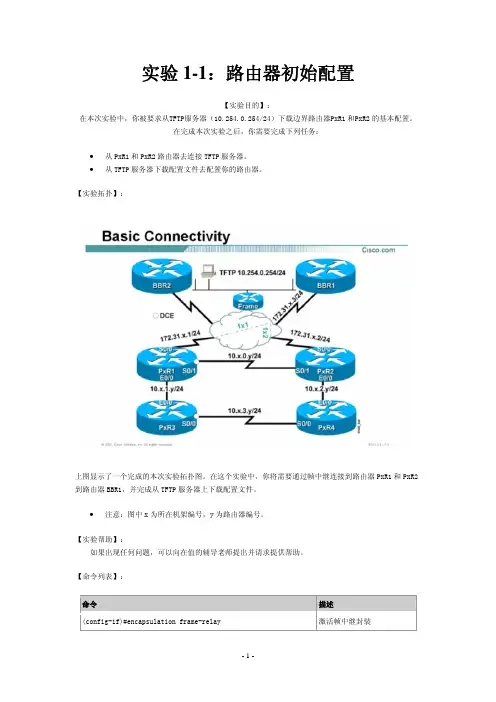
实验1-1:路由器初始配置【实验目的】:在本次实验中,你被要求从TFTP服务器(10.254.0.254/24)下载边界路由器PxR1和PxR2的基本配置。
在完成本次实验之后,你需要完成下列任务:•从PxR1和PxR2路由器去连接TFTP服务器。
•从TFTP服务器下载配置文件去配置你的路由器。
【实验拓扑】:上图显示了一个完成的本次实验拓扑图。
在这个实验中,你将需要通过帧中继连接到路由器PxR1和PxR2到路由器BBR1,并完成从TFTP服务器上下载配置文件。
•注意:图中x为所在机架编号,y为路由器编号。
【实验帮助】:如果出现任何问题,可以向在值的辅导老师提出并请求提供帮助。
【命令列表】:命令描述(config-if)#encapsulation frame-relay 激活帧中继封装(config-if)#frame-relay map ip 172.31.x.3 1x1 broadcast 映射下一跳IP地址到PVC (config-if)#ip address 172.31.x.1 255.255.255.0 给接口配置IP地址。
(config)#ip route 10.0.0.0 255.0.0.0 172.31.x.3 创建一条静态路由(config-if)no shutdown 激活一个端口【任务一】:设备路由器PxR1和PxR2使用TELNET或者其他终端程序建立与路由器建立联接。
记住在本实验中x是你的机架编号,y是你的路由器编号。
实验过程:第一步:连接路由器(PxR1和PxR2)。
你的路由器现在应该没有任何配置。
如果有,请使用erase start 命令删除配置,并使用reload命令重启路由器。
•注意:你应该使用一些最少的配置,以确保路由器能够到达TFTP服务器。
第二步:配置S0口为FRAME-RELAY封装格式。
第三步:分配IP地址给S0口。
你的IP地址应该为172.31.x.y/24, x代表你的机架编号,y代表你的路由器编号。
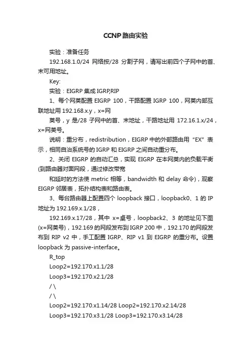
CCNP路由实验实验:准备任务192.168.1.0/24网络按/28分割子网,请写出前四个子网中的首、末可用地址。
Key:实验:EIGRP集成IGRP,RIP1、每个网荚配置EIGRP 100,干路配置IGRP 100,网荚内部互联地址用192.168.x.y,x=网荚号,y是/28子网中的首、末地址,干路地址用172.16.1.x/24,x=网荚号。
说明:重分布,redistribution,EIGRP中的外部路由用“EX”表示,相同自治系统号的IGRP 和EIGRP之间自动重分布。
2、关闭EIGRP的自动汇总,实现EIGRP在本网荚内的负载平衡(到路由器对面网段,通过修改带宽和延时的方法使metric相等,bandwidth和delay命令),观察EIGRP邻居表,拓扑结构表和路由表。
3、每台路由器上配置四个loopback接口,loopback0、1的IP 地址为192.169.x.1/28,192.169.x.17/28,其中x=桌号,loopback2、3的地址见下图(x=网荚号),192.169的网段发布到IGRP 200中,192.170的网段发布到RIP v2中,手工配置IGRP、RIP v1到EIGRP 的重分布。
设置loopback为passive-interface。
R_topLoop2=192.170.x1.1/28Loop3=192.170.x2.1/28/ \/ \Loop2=192.170.x1.14/28 Loop2=192.170.x2.14/28Loop3=192.170.x3.1/28 Loop3=192.170.x3.14/28R_left ------------- R_right说明:手工重分布在目的路由进程中进行。
redistriute 源路由进程 metric 种子度量值其它选项ping 192.170这个网段的对面路由器的loopback接口的地址,观察现象(一个通,一个不通)。
HSRP基本实验
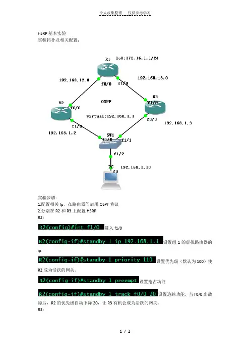
实验拓扑及相关配置:
实验步骤:
1.配置相关Ip,在路由器间启用OSPF协议
2.分别在R2和R3上配置HSRP
R2:
进入f1/0
设置组1的虚拟路由器的ip
设置优先级(默认为100)使R2成为活跃的网关。
设置抢占功能
设置追踪功能,当F0/0出故障后,R2的优先级自动下降20,让R3有机会成为活跃的网关。
R3:
3.将PC机的默认网关设置为虚拟路由器的IP。
从PC上ping R1可以通。
(第一个包因为要做ARP而丢失)。
用Traceroute可以看出此时是从R2走的。
接下来在PC上长ping R1 期间down掉R2的f0/0口,
在down掉R2后R3的状态由备用变为活跃状态:
观察ping的情况:
在R2 down掉后ping包出现一个U. ,U是R2的目标不可达,. 是R3在做ARP。

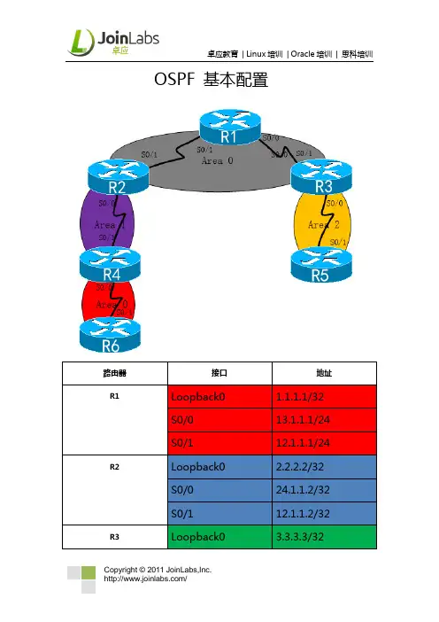
OSPF 基本配置实验要求1:如图所示配置OSPF路由协议2:区域0、1、2属于A公司,红色区域代表B公司,现在A公司把B公司收购,你要保证A公司和B公司正常通信(有二种办法,让领导任选一种)3:黄色区域中的R3和R5两台设备为公司机密数据所在,要加强安全性(二种办法,让领导任选一种)4:公司B路由条目太多,总公司希望管理员在减少路由表的前提下,不影响其它通信5:为了加强中央集权,总公司规定所有上公网的流量都通过R1出去,有利于监督和控制一:OSPF路由协议R1(config)#router ospf 110 //进程号可以自己定义R1(config-router)#router-id 1.1.1.1 //推荐手动配置router-id R1(config-router)#network 1.1.1.1 0.0.0.0 area 0R1(config-router)#network 12.1.1.0 0.0.0.255 area 0R1(config-router)#network 13.1.1.0 0.0.0.255 area 0R2(config)#router ospf 110R2(config-router)#router-id 2.2.2.2R2(config-router)#network 2.2.2.2 0.0.0.0 area 0R2(config-router)#network 12.1.1.0 0.0.0.255 area 0R2(config-router)#network 24.1.1.0 0.0.0.255 area 1R3(config)#router ospf 110R3(config-router)#router-id 3.3.3.3R3(config-router)#network 3.3.3.3 0.0.0.0 area 0R3(config-router)#network 13.1.1.0 0.0.0.255 area 0R3(config-router)#network 35.1.1.0 0.0.0.255 area 2R4(config)#router ospf 110R4(config-router)#router-id 4.4.4.4R4(config-router)#network 4.4.4.4 0.0.0.0 area 1R4(config-router)#network 24.1.1.0 0.0.0.255 area 1 R4(config-router)#network 46.1.1.0 0.0.0.255 area 0R5(config)#router ospf 110R5(config-router)#router-id 5.5.5.5R5(config-router)#network 5.5.5.5 0.0.0.0 area 2R5(config-router)#network 35.1.1.0 0.0.0.255 area 2R6(config)#router ospf 110R6(config-router)#router-id 6.6.6.6R6(config-router)#network 46.1.1.0 0.0.0.255 area 0 R6(config-router)#network 6.6.0.0 0.0.0.255 area 0 R6(config-router)#network 6.6.1.0 0.0.0.255 area 0 R6(config-router)#network 6.6.2.0 0.0.0.255 area 0 R6(config-router)#network 6.6.3.0 0.0.0.255 area 0二:不连续区域的配置1:隧道R2(config)#interface tunnel 0R2(config-if)#tunnel source 24.1.1.2 //隧道源开始的地址R2(config-if)#tunnel destination 24.1.1.4 //隧道目标地址R2(config-if)#ip add 192.168.1.1 255.255.255.0 //给隧道的地址R2(config-if)#ip ospf 110 area 0 //把隧道宣告进区域0R4(config)#interface tunnel 0R4(config-if)#tunnel source 24.1.1.4R4(config-if)#tunnel destination 24.1.1.2R4(config-if)#ip add 192.168.1.2 255.255.255.0R4(config-if)#ip ospf 110 area 02:虚链路R2(config)#router ospf 110R2(config-router)#area 1 virtual-link 4.4.4.4//注意红色标记R4(config)#router ospf 110R4(config-router)#area 1 virtual-link 2.2.2.2三:加密1:明文R3(config-if)#interface s0/0R3(config-if)#ip ospf authenticationR3(config-if)#ip ospf authentication-key 1234R5(config)#interface s0/1R5(config-if)#ip ospf authenticationR5(config-if)#ip ospf authentication-key 12342:密文R3(config)#interface s0/0R3(config-if)#ip ospf authentication message-digestR3(config-if)#ip ospf message-digest-key 1 md5 1234R5(config)#interface s0/1R5(config-if)#ip ospf authenticatio message-digestR5(config-if)#ip ospf message-digest-key 1 md5 1234四:汇总R6(config)#interface loopback 0R6(config-if)#ip ospf network point-to-point //改网络类型R3(config)#router ospf 110R3(config-router)#area 0 range 6.6.0.0 255.255.252.0五:下发默认路由R1(config)#ip route 0.0.0.0 0.0.0.0 null 0 //写一条默认路由R1(config)#router ospf 110R1(config-router)#default-information originate always。
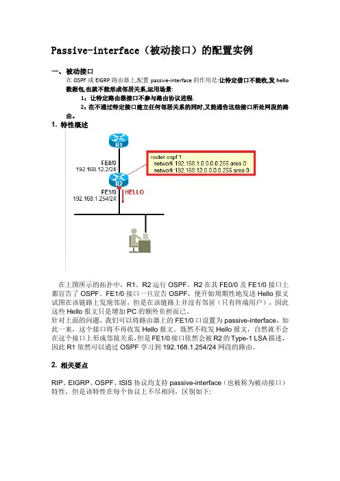
Passive-interface(被动接口)的配置实例一、被动接口在OSPF或EIGRP路由器上,配置passive-interface的作用是:让特定借口不能收,发hello 数据包,也就不能形成邻居关系,运用场景:1:让特定路由器接口不参与路由协议进程.2:在不通过特定接口建立任何邻居关系的同时,又能通告这些接口所处网段的路由。
1. 特性概述在上图所示的拓扑中,R1、R2运行OSPF,R2在其FE0/0及FE1/0接口上都宣告了OSPF。
FE1/0接口一旦宣告OSPF,便开始周期性地发送Hello报文试图在该链路上发现邻居,但是在该链路上并没有邻居(只有终端用户),因此这些Hello报文只是增加PC的额外负担而已。
针对上面的问题,我们可以将路由器上的FE1/0口设置为passive-interface,如此一来,这个接口将不再收发Hello报文。
既然不收发Hello报文,自然就不会在这个接口上形成邻接关系,但是FE1/0接口依然会被R2的Type-1 LSA描述,因此R1依然可以通过OSPF学习到192.168.1.254/24网段的路由。
2. 相关要点RIP、EIGRP、OSPF、ISIS协议均支持passive-interface(也被称为被动接口)特性,但是该特性在每个协议上不尽相同,区别如下:当然,我们在路由协议中将某个接口设置为passive-interface的前提是使用network关键字宣告了这个接口的网段,否则passive-interface就没有意义了。
passive-interface特性通常被用于某个接口的网段路由需要被其他路由器学习到,但是这个接口本身可能连接着一个末梢网络(只有主机,没有其他的路由器)的场景。
3. 配置实现将某个接口配置为被动接口:Router(config-router)# passive-interface int-type int-num将所有接口配置为被动接口,并手动激活特定接口:Router(config-router)# passive-interface defaultRouter(config-router)# no passive-interface int-type int-num典型配置示例:这是一个非常典型的场景,GS_SW是汇聚层交换机,与核心交换机之间跑OSPF。
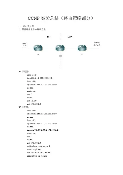
CCNP实验总结(路由策略部分)一.路由重分布1.最佳路由重分布解决方案R1下配置:inter loo 0ip add 1.1.1.1 255.255.255.0inter s0/0ip add 192.168.0.1 255.255.255.0no shurouter ripver 2no aunet 1.1.1.0net 192.168.0.0R2下配置:inter s0/0ip add 192.168.0.2 255.255.255.0no shuinter s0/1ip add 192.168.1.1 255.255.255.0no shuip route 0.0.0.0 0.0.0.0 192.168.1.2router ripver 2no aunet 192.168.0.0redistribute static metric 1router ospf 100net 192.168.1.1 0.0.0.0 a 0redistribute rip subnetsR3下配置:inter s0/1ip add 192.168.1.2 255.255.255.0no shuinter loo 0ip add 3.3.3.3 255.255.255.0ip ospf net point-to-prouter ospf 100net 192.168.1.2 0.0.0.0 a 0net 3.3.3.0 0.0.0.255 a 02.RIP下分布OSPFredistribute ospf 100 metric 1-153.EIGRP下分布OSPFredistribute ospf 100 metric 1544 200 255 1 15004.OSPF下分布RIP/EIGRPreidistribute rip/eigrp 100 subnets5.EIGRP下分布IS-ISredistribute isis level-1/-1-2/-2 metric 1544 200 255 1 15006.IS-IS下分布EIGRPredistribute eigrp 100 level-1/-1-2/-2二.被动接口RIP下只接受更新不发送更新,OSPF/IS-IS/EIGRP下不向外发送hello包,不建立邻居关系router eigrp 100passive-interface s0/0passive-interface default (全部接口)三.控制路由更新1.出向router eigrp 100distribute-list acl out interface/process路由重分布只能用出向列表(能加路由进程)2.入向router eigrp 100distribute-list acl in interface3.prefix-listip prefix-list 1 permit 1.1.1.0/24 ge 25 le 30所有B类地址的子网路由,长度不超过24ip prefix-list 1 permit 128.0.0.0/2 ge 17 le 244.加入网关distribute-list gateway prefix-list…gateway:距离矢量,到达目的网段的下一跳链路状态,通告这条路由的路由器5.基于时间的ACLtime-range aaaabsolute (绝对)/periodicperiodic Monday-Sunday 9:00 to 12:00dailyweekdays (Monday to Friday)weekend (Saturday to Sunday)access-list 100 permit tcp any any eq 80 time-range aaa6.OSPF中的分布列表不允许用出向(同一区域内LSDB要同步),入向数据库中有条目,不加路由表7.双向多点重分布时的路由回馈问题R2先于R3配置好R3会认为1.0-3.0网段是从R4发来的(管理距离问题)解决办法:1.修改R1-R3 RIP的管理距离2.去掉R38.策略路由access-list 1 permit 1.1.1.0 0.0.0.255route-map name permit num(从小往大写)match ip address address/acl num/prefix-list numset (e.g. metric 100)router ospf 100redistribute rip route-map name subnets9.IS-IS的被重分布问题需要重分布直连链路:redistribute connected10.管理距离的修改router eigrp 100distance eigrp num(内部) num(外部)distance 1 1.1.1.0 255.255.255.0/aclrouter ospf 100distance 1 1.1.1.0/acl gateway acl num11.现网不用debug,流量过大,慎用no语句12.DHCP交换信息用broadcast,每到周期的一半,再申请一次,如此循环。
CCNP一个小综合实验:要求:1.SW1为VTP的Server,其他为Client2.SW1与SW2之间链路做捆绑3.PC1为vlan10,PC2为vlan204.SW1为vlan10的根,SW2为vlan10的备用根,SW2为vlan20的根,SW1为vlan20的备用根5.SW1与SW2通过HSRP来实现设备冗余6.SW1,SW2,中心路由器之间运行OSPF协议,当在SW1宇SW2上新增加网段的时候,中心路由器能够自动学习到新增加的网段。
7.中心与分公司之间通过DMVPN建立连接8.运行EIGRP协议,让公司之间的内网可以互通。
配置:基本配置:在各个路由器、交换机上配置ip在R1 R2 R3 R5上配置默认路由并做NATSW1 SW2与R5的接口采用路由接口,其他接口为交换端口1.sw1:vtp domain ciscosw2:vtp domain ciscovtp mode clientsw3:vtp domain ciscovtp mode client2.SW1:interface Port-channel1 switchport mode trunk !interface Port-channel2 switchport mode trunk interface FastEthernet1/3 switchport mode trunk channel-group 1 mode on !interface FastEthernet1/4 switchport mode trunk channel-group 1 mode on !interface FastEthernet1/5 switchport mode trunk channel-group 2 mode on !interface FastEthernet1/6 switchport mode trunk channel-group 2 mode on !SW2:!interface Port-channel1 switchport mode trunk !interface Port-channel2 switchport mode trunk !interface FastEthernet1/3 switchport mode trunk channel-group 1 mode on !interface FastEthernet1/4 switchport mode trunkchannel-group 1 mode on!interface FastEthernet1/5switchport mode trunkchannel-group 2 mode on!interface FastEthernet1/6switchport mode trunkchannel-group 2 mode on!SU为启用状态。
CCNP实验:OSPF的五种类型数据包(1)OSPF的数据包格式:根据OSFP数据包type字段数值的不同,OSPF数据包类型分为五种,不同的type,后面Data的内容则不同。
路由表的形成与这五种数据包的交互息息相关:type=1 Hello数据包type=2 数据库描述包type=3 链路状态请求包type=4 链路状态更新包type=5 链路状态确认包结合GNS3 + Wireshark 来学习这五种类型数据包在邻接关系建立过程中所发挥的作用。
简单的拓扑以R1和R2的链路为例,看R1的s0/0和R2的s0/0如何建立邻接关系的。
关于邻接关系:(1)邻居和邻接是不同的;(邻接关系要求链路状态数据库同步)(2)点到点链路可以形成fully状态的邻接关系;(2)对于MA型链路,DR和BDR可以形成full状态的邻接关系,其他路由器是双向two-way状态的邻接关系。
(对于MA型链路,形成full状态的邻接关系代价太高,选举DR,BDR可以简化邻接关系,减少LSA洪泛)上面的例子是点到点链路。
上面是wireshark在R1的s0/0上抓包的结果。
从第14包hello 开始到第38包LS确认,然后后面就是每隔10S的互发Helllo包来维持邻接关系,一直到链路状态发生变化为止。
一,Hello数据包message type字段为1。
Hello数据包是用来建立和维护邻接关系的,为了形成邻接关系,Hello数据包所携带的一些参数必须和它的邻居保持一致,否则对方收到会丢弃。
用来协商的参数包括:掩码、hello时间间隔(默认10s),死亡时间间隔(默认四倍hello间隔)、还有可选字段等。
此外,Hello数据包还会携带源路由器的ID,如果没有换回口,则选IP最大的;区域ID,认证字段,路由器优先级,DR和BDR等内容,当有邻居的时候,还会携带邻居字段。
(hello数据包会维持init和two way两个状态,当收到对方的hello包里的邻居字段里没有自己时,则为init状态,当发现对方的hello包里的邻居字段里有自己时,则进入two way状态,标志邻居关系建立,即可以发送数据库描述数据包了)(如果是MA网络,在two way状态下要选举DR和BDR)下面是通过一些debug得出的信息:*Mar 1 00:06:15.483: OSPF: Drop packet (interface Serial0/0 down or dampened)R1#*Mar 1 00:06:23.599: %LINEPROTO-5-UPDOWN: Line protocol on Interface Serial0/0, changed state to up*Mar 1 00:06:23.623: OSPF: Interface Serial0/0 going Up (接口up)*Mar 1 00:06:23.623: OSPF: Send hello to 224.0.0.5 area 0 on Serial0/0 from 10.0.0.1*Mar 1 00:06:23.739: OSPF: rcv. v:2 t:1l:48 rid:2.2.2.2 (type=1)aid:0.0.0.0 chk:E580 aut:0 auk: from Serial0/0*Mar 1 00:06:23.739: OSPF: Rcv hello from 2.2.2.2 area 0 from Serial0/0 10.0.0.2*Mar 1 00:06:23.743: OSPF: 2 Way Communication to 2.2.2.2 on Serial0/0, state 2WAYseq 0x5BC opt 0x52 flag 0x7 len 32*Mar 1 00:06:23.747: OSPF: Send immediate hello to nbr 2.2.2.2, src address 10.0.0.2, on Serial0/0*Mar 1 00:06:23.747: OSPF: Send hello to 224.0.0.5 area 0 on Serial0/0 from 10.0.0.1*Mar 1 00:06:23.747: OSPF: End of hello processing*Mar 1 00:06:23.767: OSPF: rcv. v:2 t:2 l:32 rid:2.2.2.2aid:0.0.0.0 chk:9CD6 aut:0 auk: from Serial0/0二,数据库描述数据包当两个邻居建立通过Hello确认双方参数匹配时,则进入建立邻接关系阶段,此时会互发三种类型的OSPF数据包:数据库描述数据包,链路状态请求包和链路状态更新包。
综合实验地址需求:R1-R2:8.8.12.xR2-R5 : 8.8.25.xR2-R6 : 8.8.26.xR5-R6-R7 : 8.8.100.x每个路由器的loopback 0口如下:e.g. R3: 8.8.3.3R6的loopback口为:8.8.8.18.8.9.18.8.10.18.8.11.18.8.32.1……RIP1. 要求R2收到R1的loopback0路由的metric为5 (偏移列表)2. R1与R3之间链路作为备用链路使用(使用缺省路由)r2:ip route 0.0.0.0 0.0.0.0 e0/2 r1 :r3OSPF1. 连通所有OSPF,要求OSPF内Ping通;2. Area 0做最安全的OSPF认证;3. Virtual-link用最合适的方式建立;(首先手工指定id。
)4. R6的Loop8~11要以外部路由的方式学习到,并累加metric;??E15. R6的Loop32~35同样发布(从分布)到Area26中,要求所有条目的路由被OSPF隐藏,不能用路由过滤;(汇总)EIGRP access 1 per 8.8.8.0 0.0.3.255; access 2 per 8.8.32.0 0.0.3.255;route-map1.R2学习到的8.8.7.7是等价负载均衡的。
(R2先走从分布进去的路)acce r6 distance 200R5 10 per 8.8.7.0 0.0.0.255 rooute os 100 distance 200 6.6.6.62. R7的loopback0 以外部路由的方式发进EIGRPRedistribute1. RIP与OSPF重发布,将R1的loopback111隐藏r1 (过滤)acc 10 per 8.8.111.0 0.0.0.255 rou-map a deny (过滤1.1.1 让其他通过)10 map add2. OSPF与EIGRP重发布。
思科CCNP认证OSPF之认证、虚链路及过滤案例分析本⽂讲述了思科CCNP认证OSPF之认证、虚链路及过滤。
分享给⼤家供⼤家参考,具体如下:认证1:链路认证 //防⽌链路接⼊⾮法路由器(⽆授权),在链路的所有设备都需要开启1> 明⽂认证 //不安全在IOS15.2的版本中的配置:int e0/0 //进⼊需要做认证的接⼝ip ospf authentication //开启明⽂认证ip ospf authentication key-chain k //k为key-chain的名字,⾃⾏决定key chain kkey 1key-string cisco //输⼊明⽂认证的密钥在IOS15.4版本中的配置:int e0/0 //进⼊需要认证的接⼝ip ospf authentication //开启明⽂认证ip ospf authentication-key cisco //(密钥,可不写)将密钥进⾏⽐对,若⽐对成功则认证成功。
PS:开启明⽂认证后,本地的hello包中认证类型的字段发⽣变化。
未认证时为0,开启认证后将0置位为1。
做认证的邻居间必须保持⼀致。
若仅链路的⼀端开启认证,则整条链路的路由不互通。
同时明⽂认证若仅开启认证,不输⼊密钥,则丧失了认证的安全性,容易被他⼈窃取数据。
2> md5认证 //安全int e0/0 //进⼊需要做md5认证的接⼝ip ospf authentication message-digest //开启认证ip ospf authentication message-digest-key 1 md5 cisco //输⼊密钥PS:与明⽂认证⼀样,邻居间的md5认证密钥必须保持⼀致,否则不能进⾏通信。
2:区域认证 //防⽌区域接⼊⾮法路由器,区域内所有设备都需要开启1> 明⽂认证router ospf 1area 0 authenticationint e0/0ip ospf authentication-key cisco //接⼝写⼊认证密钥2> md5认证router ospf 1area 0 authentication message-digest //区域0开启md5认证int e0/0ip ospf message-digest-key 1 md5 cisco //接⼝写⼊md5认证密钥PS:在路由器上开启关于某个区域的明⽂或密⽂认证,实际上是将该路由上⼯作与此区域的接⼝修改认证类型字段为明⽂或密⽂,密钥需要在各个接⼝逐⼀配置。
CCNP TS DC一:目录目录1:EIGRP 标准配置 (2)2:neighbor s (3)2.1 AS (3)2.2 K VAULE MISMATCH (4)2.3 hello send time /hold time mismatch (5)2.4 EIGRP sec ip address (6)3: network (7)3.1 宣告不精确 (7)3.2 由于过滤不精确导致宣告不成功 (8)4:EIGRP summary (8)4.1 汇总不精确,导致汇总不成功 (8)4.2 EIGRP 汇总特性 (9)二:OSPF (9)2.1 ospf basic configuration (9)2.2 neighbor ts (10)2.2.1 Hello /dead (10)2.2.2 Area id (11)2.2.3 Authentication (11)2.2.4 Stub area flag (11)2.3 NETWORK (宣告)错误 (12)2.3.1 宣告不精确 (12)2.3.2 区域宣告不准确 (12)2.4 OSPF 增强的NEIGHBOR 错误 (12)2.4.1 OSPF HAVE SAME ROUTER-ID (12)2.4.2 OSPF MTU 问题 (13)三:BGP TS (13)3.1 IBGP基本配置 (13)3.2 EBGP 基本配置 (14)3.3 BGP NEIGHBOR TS (14)3.3.1 对等体不可达 (14)3.3.2错误的AS 号 (15)3.3.3 忘记设置EBGP 多跳 (15)3.4 NETWORK 标准配置 (15)3.5 NETWORK TS (16)3.5.1 错误的前缀宣告 (16)3.5.2 错误的掩码宣告 (16)3.6 BGP 水平分割引起的路由不被学习问题 (16)1)full mesh (16)2)route reflect (17)3.7 BGP NEXT-HOP 问题 (17)1)使得NEXT-HOP 可达 (17)2)设置next-hop-self (17)1:EIGRP 标准配置R2#show run | b router eigrprouter eigrp 2010network 2.2.2.0 0.0.0.255network 12.12.12.0 0.0.0.255no auto-summary*May 22 10:03:01.427: %DUAL-5-NBRCHANGE: IP-EIGRP(0) 2010: Neighbor 12.12.12.1 (Serial1/0) is up: new adjacencyR2#show ip eigrp 2010 neighborIP-EIGRP neighbors for process 2010H Address Interface Hold Uptime SRTT RTO Q Seq(sec) (ms) Cnt Num0 12.12.12.1 Se1/0 10 00:02:12 16 200 0 4 2:neighbor s2.1 ASR2#show ip eigrp 2010 neighborIP-EIGRP neighbors for process 2010R2#show ip protocolsRouting Protocol is "eigrp 2010"Outgoing update filter list for all interfaces is not setIncoming update filter list for all interfaces is not setDefault networks flagged in outgoing updatesDefault networks accepted from incoming updatesEIGRP metric weight K1=1, K2=0, K3=1, K4=0, K5=0EIGRP maximum hopcount 100EIGRP maximum metric variance 1Redistributing: eigrp 2010EIGRP NSF-aware route hold timer is 240sAutomatic network summarization is not in effectMaximum path: 4Routing for Networks:2.2.2.0/2412.12.12.0/24Routing Information Sources:Gateway Distance Last Update12.12.12.1 90 00:06:45Distance: internal 90 external 170Outgoing update filter list for all interfaces is not setIncoming update filter list for all interfaces is not setDefault networks flagged in outgoing updatesDefault networks accepted from incoming updatesEIGRP metric weight K1=1, K2=0, K3=1, K4=0, K5=0EIGRP maximum hopcount 100EIGRP maximum metric variance 1Redistributing: eigrp 201EIGRP NSF-aware route hold timer is 240sAutomatic network summarization is not in effectMaximum path: 4Routing for Networks:12.12.12.0/24Routing Information Sources:Gateway Distance Last UpdateDistance: internal 90 external 170处理方法:重新配置,统一AS NUMBER2.2 K VAULE MISMATCHR1(config-router)#metric weights 0 1 1 1 1 1*May 22 10:14:19.907: %DUAL-5-NBRCHANGE: IP-EIGRP(0) 2010: Neighbor 12.12.12.2 (Serial1/1) is down: metric changedR1(config-router)#*May 22 10:14:22.427: %DUAL-5-NBRCHANGE: IP-EIGRP(0) 2010: Neighbor 12.12.12.2 (Serial1/1) is down: K-value mismatchR1#show ip protocolsRouting Protocol is "eigrp 2010"Outgoing update filter list for all interfaces is not setIncoming update filter list for all interfaces is not setDefault networks flagged in outgoing updatesDefault networks accepted from incoming updatesEIGRP metric weight K1=1, K2=1, K3=1, K4=1, K5=1R2#show ip protocolsRouting Protocol is "eigrp 2010"Outgoing update filter list for all interfaces is not setIncoming update filter list for all interfaces is not setDefault networks flagged in outgoing updatesDefault networks accepted from incoming updatesEIGRP metric weight K1=1, K2=0, K3=1, K4=0, K5=0TS 方式NO 掉之前的错误命令,或者利用命令行进行修改2.3 hell o send time /hold time mismatchR2(config)#int s1/0R2(config-if)#ip hold-time eigrp 2010 4R2(config-if)#*May 22 10:22:21.107: %DUAL-5-NBRCHANGE: IP-EIGRP(0) 2010: Neighbor 12.12.12.1 (Serial1/0) is down: Interface Goodbye received*May 22 10:22:21.383: %DUAL-5-NBRCHANGE: IP-EIGRP(0) 2010: Neighbor 12.12.12.1 (Serial1/0) is up: new adjacencyR2(config-if)#*May 22 10:22:25.427: %DUAL-5-NBRCHANGE: IP-EIGRP(0) 2010: Neighbor 12.12.12.1 (Serial1/0) is down: Interface Goodbye received*May 22 10:22:25.791: %DUAL-5-NBRCHANGE: IP-EIGRP(0) 2010: Neighbor 12.12.12.1 (Serial1/0) is up: new adjacencyR2(config-if)#*May 22 10:22:29.855: %DUAL-5-NBRCHANGE: IP-EIGRP(0) 2010: Neighbor 12.12.12.1 (Serial1/0) is down: Interface Goodbye received*May 22 10:22:30.083: %DUAL-5-NBRCHANGE: IP-EIGRP(0) 2010: Neighbor 12.12.12.1 (Serial1/0) is up: new adjacencyR1#show ip eigrp 2010 neighborIP-EIGRP neighbors for process 2010H Address Interface Hold Uptime SRTT RTO Q Seq(sec) (ms) Cnt Num0 12.12.12.2 Se1/1 2 00:00:03 13 200 0 26R2#show ip eigrp 2010 neighborsIP-EIGRP neighbors for process 2010H Address Interface Hold Uptime SRTT RTO Q Seq(sec) (ms) Cnt Num0 12.12.12.1 Se1/0 13 00:00:03 1968 5000 0 112TS 方法将计时器统一,或者将错误命令删除EIGRP BROADCAST PTP EVERY 5 SEC602.4 EIGRP sec ip ad dressEIGRP 主从地址问题Eigrp 永远只使用接口主地址发送HELLO 消息,他要求直连设备必须在相同的子网。
一、实验目的:1、掌握OSPF虚链路的配置二、实验拓扑:三、实验步骤1、如图配置OSPF网络,配置如下:R1:R1(config)#int s1/1R1(config-if)#ip add 172.16.224.1 255.255.255.0R1(config-if)#no shutR1(config)#int loop 0R1(config-if)#ip add 172.16.1.3 255.255.255.0R1(config)#int loop 1R1(config-if)#ip add 172.16.0.3 255.255.255.0R1(config-if)#exitR1(config)#router ospf 1R1(config-router)#network 172.16.224.0 0.0.0.255 area 51 R1(config-router)#network 172.16.0.0 0.0.0.255 area 0R1(config-router)#network 172.16.1.0 0.0.0.255 area 0R1(config-router)#R2:R2(config)#int s1/0R2(config-if)#ip add 172.16.224.2 255.255.255.0R2(config-if)#no shutR2(config)#int s1/2R2(config-if)#ip add 172.16.240.1 255.255.255.0R2(config-if)#no shutR2(config)#int loop 0R2(config-if)#ip add 172.16.3.1 255.255.255.0R2(config-if)#exitR2(config)#router ospf 1R2(config-router)#network 172.16.224.0 0.0.0.255 area 51R2(config-router)#network 172.16.3.0 0.0.0.255 area 51R2(config-router)#network 172.16.240.0 0.0.0.255 area 3R3:R3(config)#int s1/1R3(config-if)#ip add 172.16.240.2 255.255.255.0R3(config-if)#no shutR3(config)#int loop 0R3(config-if)#ip add 172.16.252.1 255.255.255.0R3(config)#int loop 1R3(config-if)#ip add 172.16.248.1 255.255.255.0R3(config)#router ospf 1R3(config-router)#network 172.16.240.0 0.0.0.255 area 32、使用show ip route、show ip ospf nei查看OSPF配置结果。
CCNP之OSPF实验案例实验要求:1、总部和分部之间通过帧中继实现互访,协议要求采用OSPF。
要求帧中继不能动态获取映射,也不能静态配置映射2、配置好OSPF协议,验证邻居建立3、确保整个内网全网可达4、确保骨干区域高安全性5、尽量减少网关路由表条目6、R1、R3、R9性能不足,尽量减少其路由条目7、确保总部和分部都只通过自己的ISP上网8、不能出现主机路由实验拓扑:实验步骤:1、帧中继的配置:由于不能配置帧中继动态和静态映射,所以只能采用点对点子接口模式进行配置,在接口下声明自己的DLCI。
其中R5的Route-ID是1.1.1.1,R6的Route-ID是2.2.2.2。
由于是点对点连接,所以不存在DR和BDR。
FR-SW:FR-SW(config)#frame-relay switchingFR-SW(config)#int s0/0FR-SW(config)#no shutFR-SW(config-if)#encapsulation frame-relayFR-SW(config-if)#clock rate 64000FR-SW(config-if)#frame-relay intf-type dceFR-SW(config-if)#frame-relay route 102 int s0/1 201FR-SW(config)#int s0/1FR-SW(config)#no shutFR-SW(config-if)#encapsulation frame-relayFR-SW(config-if)#clock rate 64000FR-SW(config-if)#frame-relay intf-type dceFR-SW(config-if)#frame-relay route 201 int s0/0 102R5:R5(config)#int s2/1R5(config-if)#no shutR5(config-if)#encapsulation frame-relayR5(config)#int s2/1.1 point-to-pointR5(config-subif)#ip add 172.16.10.1 255.255.255.0R5(config-subif)#frame-relay int-dlci 102R5(config-subif)#no frame-relay inverse-arpR6:R6(config)#int s1/1R6(config-if)#no shutR6(config-if)#encapsulation frame-relayR6(config-if)#ip add 172.16.10.2 255.255.255.0R6(config-if)# frame-relay int-dlci 201R6(config-if)#no frame-relay inverse-arp测试帧中继连接情况:FR-SW#show frame-relay rouInput Intf Input Dlci Output Intf Output Dlci StatusSerial0/0 102 Serial0/1 201 activeSerial0/1 201 Serial0/0 102 activeR6#show ip ospf intSerial1/1.1 is up, line protocol is upInternet Address 172.16.10.2/24, Area 0Process ID 1, Router ID 2.2.2.2, Network Type POINT_TO_POINT, Cost: 64 Transmit Delay is 1 sec, State POINT_TO_POINT,Timer intervals configured, Hello 10, Dead 40, Wait 40, Retransmit 5oob-resync timeout 40Hello due in 00:00:09Supports Link-local Signaling (LLS)Index 1/1, flood queue length 0Next 0x0(0)/0x0(0)Last flood scan length is 1, maximum is 6Last flood scan time is 0 msec, maximum is 4 msecNeighbor Count is 1, Adjacent neighbor count is 1Adjacent with neighbor 1.1.1.1Suppress hello for 0 neighbor(s)R5#show ip os nei detailNeighbor 2.2.2.2, interface address 172.16.10.2In the area 0 via interface Serial2/1.1Neighbor priority is 0, State is FULL, 12 state changesDR is 0.0.0.0 BDR is 0.0.0.0Options is 0x52LLS Options is 0x1 (LR)Dead timer due in 00:00:35Neighbor is up for 00:35:14Index 2/2, retransmission queue length 0, number of retransmission 3 First 0x0(0)/0x0(0) Next 0x0(0)/0x0(0)Last retransmission scan length is 1, maximum is 1Last retransmission scan time is 0 msec, maximum is 0 msec2、全网启用OSPF 协议(配置端口IP 和环回口步骤省略)R1:R1(config)#router ospf 1R1(config-router)#net 172.16.1.1 0.0.0.0 a 1R1(config-router)#net 172.16.2.1 0.0.0.0 a 1R1(config-router)#net 172.16.3.2 0.0.0.0 a 1R1(config-router)#area 1 stub //配置区域1 为末节路由R2:R2(config)#router ospf 1R2(config-router)#net 172.16.3.1 0.0.0.0 a 1R2(config-router)#net 172.16.8.2 0.0.0.0 a 0R2(config-router)#area 1 stubR3:R3(config)#router ospf 1R3(config-router)#net 172.16.4.1 0.0.0.0 a 2R3(config-router)#net 172.16.5.1 0.0.0.0 a 2R3(config-router)#net 172.16.6.2 0.0.0.0 a 2R3(config-router)#area 2 stub //配置区域2 为末节路由R4:R4(config)#router ospf 1R4(config-router)#net 172.16.6.1 0.0.0.0 a 2R4(config-router)#net 172.16.9.2 0.0.0.0 a 0R4(config-router)#area 2 stubR5:R5(config)#router ospf 1R5(config-router)#net 172.16.8.1 0.0.0.0 a 0R5(config-router)#net 172.16.9.1 0.0.0.0 a 0R5(config-router)#net 172.16.10.1 0.0.0.0 a 0R5(config-router)#default-information originate //启用OSPF默认路由R6:R6(config)#router ospf 1R6(config-router)#net 172.16.10.2 0.0.0.0 a 0R6(config-router)#net 10.1.1.1 0.0.0.0 a 3R6(config-router)#default-information originate //启用OSPF默认路由R7:R7(config)#router ospf 1R7(config-router)#net 10.1.1.2 0.0.0.0 a 3R7(config-router)#net 10.1.2.1 0.0.0.0 a 3R7(config-router)#net 10.1.3.1 0.0.0.0 a 3R8:R8(config)#router ospf 1R8(config-router)#net 10.1.3.2 0.0.0.0 a 3R8(config-router)#net 10.1.4.1 0.0.0.0 a 4R8(config-router)#area 4 stub //配置区域4为末节路由R9:R9(config)#router ospf 1R9(config-router)#net 10.1.4.2 0.0.0.0 a 4R9(config-router)#net 10.1.5.1 0.0.0.0 a 4R9(config-router)#area 4 stub因为不能出现主机路由,所以必须在每个环回口下配置OSPF点对点模式: (config-if)#ip ospf network point-to-point验证末节路由:R1#show ip ospfArea 1Number of interfaces in this area is 3It is a stub areaArea has no authenticationSPF algorithm last executed 01:08:53.436 agoSPF algorithm executed 6 timesArea ranges areNumber of LSA 8. Checksum Sum 0x048879Number of opaque link LSA 0. Checksum Sum 0x000000Number of DCbitless LSA 0Number of indication LSA 0Number of DoNotAge LSA 0Flood list length 0R3#show ip ospfArea 2It is a stub areaArea has no authenticationSPF algorithm last executed 01:28:33.156 agoSPF algorithm executed 4 timesArea ranges areNumber of LSA 8. Checksum Sum 0x04C421Number of opaque link LSA 0. Checksum Sum 0x000000 Number of DCbitless LSA 0Number of indication LSA 0Number of DoNotAge LSA 0Flood list length 0R5#show ip ospfArea BACKBONE(0)Number of interfaces in this area is 3Area has no authenticationSPF algorithm last executed 00:46:27.944 agoSPF algorithm executed 21 timesArea ranges areNumber of LSA 13. Checksum Sum 0x07169ENumber of opaque link LSA 0. Checksum Sum 0x000000 Number of DCbitless LSA 0Number of indication LSA 0Number of DoNotAge LSA 4Flood list length 0R9#show ip ospfArea 4Number of interfaces in this area is 2It is a stub areaArea has no authenticationSPF algorithm last executed 00:47:24.176 agoSPF algorithm executed 16 timesArea ranges areNumber of LSA 8. Checksum Sum 0x041E9ENumber of opaque link LSA 0. Checksum Sum 0x000000 Number of DCbitless LSA 0Number of indication LSA 0Number of DoNotAge LSA 0Flood list length 0R7#show ip ospfArea 3This area has transit capabilityArea has no authenticationSPF algorithm last executed 00:47:41.596 agoSPF algorithm executed 12 timesArea ranges areNumber of LSA 14. Checksum Sum 0x0D84E8Number of opaque link LSA 0. Checksum Sum 0x000000Number of DCbitless LSA 0Number of indication LSA 0Number of DoNotAge LSA 0Flood list length 03、启用OSPF区域汇总:因为R1、R3、R9性能不足,以及为了减少网关的路由条目,所以有必要在每个区域的ABR 上进行汇总。