Part list
- 格式:xls
- 大小:26.50 KB
- 文档页数:1

专利名称:PREPARING SYSTEM FOR PART LIST 发明人:SHIOZAKI TORU,OTANI TAKANORI 申请号:JP24524888申请日:19880929公开号:JPH0295552A公开日:19900406专利内容由知识产权出版社提供摘要:PURPOSE:To automatically prepare a part list stating an equivalent part by providing a memory part storing the data of individual part packaged in a device, a memory part storing the library information of equivalent parts capable of alternative use for a part and an output part outputting a part list from the information of the equivalent part selected with a selection reference. CONSTITUTION:A retrieval part 3 retrieving the device packaged part stored in a part data memory part 1 is provided inside an equivalent part data memory 2. The selection reference of the equivalent part to be output to a part list from the equivalent part data obtd. by the retrieval of this retrieval part 3 is instructed by an equivalent part selection instruction part 4. Based on this selection reference the equivalent part capable of alternate use for a part is selected. From the information of this selected equivalent part, the part list stating the equivalent part by the output part 4 is prepared automatically and simply.申请人:NEC CORP更多信息请下载全文后查看。
EDI设置及操作
前提要求:
略
负责部门及人员;
此略, 参见以下部分
流程说明:
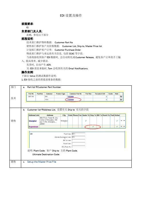
技术部门维护物料数据: Customer Part No
销售部门维护客户及价格数据: Customer List, Ship to, Master Price list
计划部门维护客户订单: Customer Purchase Order
物流部门维护与承运商有关信息, 包括SCAC等字段.
当系统接收到客户EDI数据时, 会自动转化成Customer Release, 避免客户订单的手工输入, 提高效率, 减少错误.
发货时, 自动产生ASN.
另: EDI消息来临时, Tom会收到有关的Email Notifications.
操作实例:
下面以Volvo的测试数据作说明:
1, EDI接收之前的需提前准备的数据:
b.Customer list→Address List, 设置有关Ship to 有关的字段
说明: Plant Code: 客户Ship to 方的Plant Code.
Ultimate Destination Code:
g.send the ASN message out by selecting 'Re-send' on the EDI transaction screen
3, 其它事宜
a.可在EDI Log中看到EDI事务的详细记录.
b.如ASN信息出错, 可Customer Shipping Menu→History→Regenerate ASN
完成后的处理
略.。
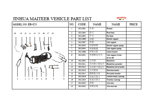
JINHUA MAITEER VEHICLE PART LISTMODEL NO: EB-023NO:CODE NAME NAMEPRICE1 50212001 车架 Froame2 50212004 前叉 Front fork3 50212005 平叉 Flat fork4 50212006 双撑 Double support5 50212007 单撑 Side support6 50213033 双撑弹簧 Double support spring7 50213034 单撑弹簧 Side support spring8 50212009 护板支架 Shield bracket 9 50213031 单撑断电开关 Side support switch of cut off 10 50212002 方向把Handlebar11 50212011 方向把上固定片 Handlebar up holder 12 50212012 方向把下固定片 Handlebar down holder 13 50212010 方向把座 Direction holder 14 50212015 脚踏板支架 Feet pedal bracket 1550212016 电池压条1 Slotted battery layering 16 50212023 电池压条2 T-battery layering 17 50213023 座锁 Seat lock 1850213022座锁拉线Seat lock line1 5 7 9 4 6 3 81013121114151617182JINHUA MAITEER VEHICLE PART LISTMODEL NO: EB-023NO: CODENAMENAMEPRICE1 50213047 前铝轮 Front aluminum rim2 50213044 碟刹盘 Disc3 57005005 前减震器 Front shock absorber4 50213012 三大摇臂 Three swing arm assy5 50213048 速度传感器 Speed sensor6 50213053 钢碗组合 Steel ball bushing assy7 57011004 闪光器 Flash organ8 57011003 喇叭 horn9 50212008 电门锁支架 Fixing base of power lock10 50213024 电门锁 Power lock 11 57006010 外胎 Outside tire 12 57006011 内胎 Inside tire 13 50213018 前轮轴 Front axel14 50213019 前轮轴衬套 Front axel bushing assy 15 50213045内六角螺钉 Disc nut 16 17 18514136789101 2 3 4 11 1215JINHUA MAITEER VEHICLE PART LISTMODEL NO: EB-023NO: CODENAMENAMEPRICE1 57004004 电池Battery2 57011007 报警器(选配) Annunciator (choice )3 57011001 转换器 Voltage changer4 57002013 控制器 Controller5 57007020 瓷接线板 Base board of all cable6 50213021 平叉轴 Flat fork axel7 57005021 后减震器 Rear shock absorption8 50213033 中撑缓冲块 Buffer kick9 50212021 左脚蹬 Left pedal 10 50212022 右脚蹬 Right pedal 11 57022005铭牌 Nameplate 12 13 14 15 16 17 181 2345678 10911JINHUA MAITEER VEHICLE PART LISTMODEL NO: EB-023NO:CODENAMENAMEPRICE1 57001009 电机 Motor2 57006010 外胎 Outside tire3 57006011 内胎 Inside tire4 50212019 电机拉杆 Motor pole5 57001009-1 制动毂盖 Motor protect cover6 57001009-2 保险片 Safety clip7 57001009-3自锁螺母 Locknut 8 9 10 11 12 13 14 15 16 17 1812 347 65JINHUA MAITEER VEHICLE PART LISTMODEL NO: EB-023NO:CODENAMENAMEPRICE1 50211026 后内泥板 Right wheel fender2 50211014 后泥板 Rear fender of board3 50211017 左平叉护板 Left cover of flat fork4 50211018 右平叉护板 Right cover of flat fork5 50211019 平叉装饰条 Decorate strip6 50211020 平叉装饰条 Decorate strip7 50211019 平叉环型装饰板 Decorate ring8 50211020平叉环型装饰板 Decorate ring 9 10 11 12 13 14 15 16 17 186 4 8 21735JINHUA MAITEER VEHICLE PART LISTMODEL NO: EB-023NO:CODENAMENAMEPRICE1 50211027 大灯 Headlight2 50213032 仪表Meter3 50211028 前左转向灯 Left turning lights4 50211029 前右转向灯 Right turning lights5 50213025 左开关把座 Left switch holder6 50213026 右开关把座 Right switch holder7 50213027 左刹把 Left brake8 50213043 碟刹泵 Disc pump9 50213028 左副把 Left handlebar 10 50213029 转把 Throttle grip 11 50712010 左后视镜 Left mirror 12 50712011 右后视镜 Right mirror 13 50213046碟刹管固定卡 Brake cable holder 14 15 16 17 18412102681 11 3 9 5 713JINHUA MAITEER VEHICLE PART LISTMODEL NO: EB-023NO:CODENAMENAMEPRICE1 5XY23002 主线束 Main cable 2 50213016 后刹车线 Left brake cable3 50213061 里程线 Distance cable4 57003009充电器 Charger 5 6 7 8 9 10 11 12 13 14 15 16 17 183 12 4JINHUA MAITEER VEHICLE PART LISTMODEL NO: EB-023NO :CODE NAME NAME PRICE150211009 面板Faceplate2 50213002 面板前压板 Faceplate press board3 50213001 面板装饰条 Faceplate decorate slat4 50213049 保险杠(选配) Bumper (choice )5 50213049保险杠衬套(选配) Bumper bushing assy (choice )6 7 8 9 10 11 12 13 14 1516 17514323JINHUA MAITEER VEHICLE PART LISTMODEL NO: EB-023NO: CODENAMENAMEPRICE150211015 前档泥板1 Front fender of wheel,part-1 2 50211016 前档泥板2Front fender of wheel,part-23 50213006 左摇臂装饰板 Left decorate board of swing arm4 50213007 右摇臂装饰板 Right decorate board of swing arm5 50213004 左前叉装饰板 Left decorate board of front fork6 50213005右前叉装饰板 Right decorate board of front fork 7 8 9 10 11 12 13 14 15 1617 185 6 4 321JINHUA MAITEER VEHICLE PART LISTMODEL NO: EB-023NO: CODENAMENAMEPRICE1 50211001 档风板上板 Up-wind board2 20211002 档风板下板 Down-wind board3 50213003 面板后压板 Press board of wind board4 50211022号码盖 Number cover 5 6 7 8 9 10 11 12 13 14 15 1617 18123 4JINHUA MAITEER VEHICLE PART LISTMODEL NO: EB-023NO: CODE NAME NAME PRICE1 50211012 左护板 Left fense board 250211013 右护板 Right fense board 350211037 脚踏板左连接板 Left min. board connected pedal 450311038 脚踏板右连接板 Right min. board connected pedal 550211006 左护板小板 Cover of left fense board 650211025 后风阁 Rear wind cabinet 750213008 后上装饰板 Up-rear decorate strip 850213009 后下装饰板 Down-rear decorate strip 950211010 左边条 R. fense strip 1050211011 右边条 L. fense strip1150212013 左把手 Left gripe 1250212014 右把手 Right gripe 1350213024 行李箱锁 Baggage trunk lock 1415 1617187 6 8 5 3 1 2 4 9 10 11 12 13JINHUA MAITEER VEHICLE PART LISTMODEL NO: EB-023 NO: CODE NAME NAME PRICE1 50211003 脚踏板 Pedal board 250211008 车架档泥板 Frame fender 350211004 充电板盖 Charge cover 450211007 充电板 Charge board 550211004 充电板合页 Folder 650213024 充电板锁 Lock of charge cover 750213010 脚踏板左铝板 Left footrest board 850213011 脚踏板右铝板 Right footrest board 95XY00003 充电器座 Charger holder 10111213141516172 53 64 1 7 8 9JINHUA MAITEER VEHICLE PART LISTMODEL NO: EB-023NO: CODE NAME NAME PRICE1 50211021 行李箱 Travel luggage2 57020003 空气开关 Air switch 350211024 行李箱内盖1 Travel Luggage cover-1 450211024 行李箱内盖2 Travel Luggage cover-2 550211023 行李箱内盖3 Travel Luggage cover-3 650213039 座垫 Seat 750213041 座垫合页 folder 891011121314151617184 2 3 156 7JINHUA MAITEER VEHICLE PART LISTMODEL NO: EB-023 NO: CODE NAME NAME PRICE1 50211030 后尾灯 Taillight assy 250213038 后衣架 Rear cargo holder 350213040 靠背 Lazyback 450212018 牌照支架 License tag holder 550213059 侧反射器 Side reflecting glass 650213059 侧反射器 Side reflecting glass 750213058 后反射器 Rear reflecting glass 850212017 后尾灯三角支架 Triangle support of taillight 910111213141516171 2 5 4 6 7 3 8。
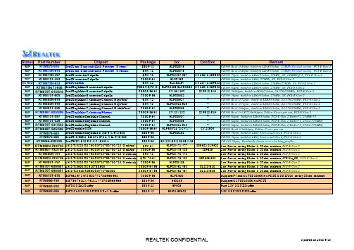
Status Part Number Chipset Package Ixx Cxx/Sxx RemarkM/P RTM875-614Intel-Atom/Diamondville & Pineview (Nettop)SSOP 489LPRS545CK505 Rev1.0 48pin, build-in LDO/33ohm, 25MHz Crystal saving, PCI-E Gen.2 M/P RTM875N-614Intel-Atom/Diamondville & Pineview (Netbook)QFN 489LPRS545CK505 Rev1.0 48pin, build-in LDO/33ohm, 25MHz Crystal saving, PCI-E Gen.2 M/P RTM875N-397Intel-Montevina/Calpella QFN 729LPRS387/397CY28648/8SP553CK505 72pin, build-in LDO/33ohm, 27MHz_SS, CLKREQ*8, PCI-E Gen.2M/P RTM875T-363Intel-Montevina/Calpella TSSOP 649LPR363CK505 64pin, build-in LDO, 27MHz_SS, PCI-E Gen.2ES Now RTM875N-632Intel-Calpella QFN 329LRS3197CY28748/8SP583CK505 32pin, build-in LDO/33ohm, 27MHz/27MHz_SS, PCI-E Gen.2M/P RTM875N(T)-606Intel-Eaglelake/Montevina/Calpella TSSOP/QFN 649LPRS355/9LPRS365CY28548/8SP530CK505 64pin, build-in LDO/33ohm, 27MHz_SS, PCI-E Gen.2M/P RTM875T-615/616Intel-Eaglelake/Montevina/Calpella TSSOP 56/64CV194/1938XP548/549CK505 56/64pin, build-in LDO/33ohm, 24.576/25MHz, PCI-E Gen.2M/P RTM875T-605Intel-Eaglelake/Montevina/Calpella TSSOP 569LPRS502CK505 56pin, build-in LDO/33ohm, 27MHz_SS, PCI-E Gen.2M/P RTM885N-914Intel-Eaglelake/Tylersburg Channel (High-end)QFN 729LPRS914-CK505 Rev1.0 72pin, build-in LDO/33ohm, 24.576/25MHz, PCI-E Gen.2M/P RTM885N-919Intel-Eaglelake/Tylersburg Channel (High-end)QFN 729LPRS918/919-CK505 Rev1.0 72pin, build-in LDO/33ohm, 24.576/25MHz, PCI-E Gen.2M/P RTM885T-926Intel-Eaglelake/Tylersburg Channel (Middle-end)TSSOP 649LPRS926-CK505 Rev1.0 64pin, build-in LDO/33ohm, 24.576/25MHz, PCI-E Gen.2M/P RTM886T-805/806Intel-Eaglelake/Tylersburg/Piketon TSSOP 56/64CV184/1838XP518/519CK505 Rev1.0 (YC2)56/64pin, Yellow Cover pin out, PCI-E Gen.2M/P RTM875T-587Intel-Bearlake/Eaglelake Channel TSSOP 649LPRS587-CK505 64pin, build-in LDO/33ohm, PCI-E Gen.2,Turbo*2, 25MHz*2M/P RTM875T-529Intel-Bearlake/Eaglelake Channel TSSOP 649LPRS509-CK505 64pin, build-in LDO/33ohm, PCI-E Gen.2,Turbo*1, 25/24.576MHzM/P RTM875T-531/533Intel-Bearlake/Eaglelake Channel TSSOP 649LPRS511/513-CK505 64pin, build-in LDO/33ohm, PCI-E Gen.2,Turbo*2, 25/24.576MHzM/P RTM868T-505/506Intel-Bearlake OEM TSSOP 56/649LP505-1&-2/CV174CY28505CK505 Rev0.9 56/64pin, Yellow Cover pin outM/P RTM876-665Intel-Bearlake/Eaglelake & SiS 671/672/680SSOP 569LPRS808CK505 56pin, build-in LDO, Universal Clock, PCI-E Gen.2M/P RTM876-660Intel-945/965 & SiS 671/672 & VIA P4M900SSOP 56CK505 56pin, build-in LDO, Universal Clock, PCI-E Gen.2M/P RTM866-480/485Intel-955X/945(P/G/GC)/910GL SSOP 56954128/954129/954119CK 410 56pin, Absolutely linear over-clocking profileM/P RTM880N-790/793AMD-RS880/RD790/RS780+SB700/710 (Desktop)QFN 649LPRS471/4778SP622/8LP622Low Power, saving 50ohm & 33ohm resistors, PCI-E Gen.2M/P RTM880T-792/794AMD-RS880/RD790/RS780+SB700/710 (Desktop)TSSOP 569LPRS475/4858SP625Low Power, saving 50ohm & 33ohm resistors, PCI-E Gen.2M/P RTM880N-791AMD-RS880/RD790/RS780+SB700/710 (Notebook)QFN 729LPRS470/478Low Power, saving 50ohm & 33ohm resistors, PCI-E Gen.2M/P RTM880N-795/796AMD-RS880/RD790/RS780+SB700/710 (Notebook)QFN 72/649LPRS476/4808SP626/628Low Power, saving 50ohm & 33ohm resistors, 27MHz_SS, PCI-E Gen.2M/P RTM880T-797AMD-RS880/RD790/RS780+SB700/710 (Notebook)TSSOP 569LPRS489Low Power, saving 50ohm & 33ohm resistors, PCI-E Gen.2M/P RTM870T-600/601AMD-RS600/RC610+SB600TSSOP 64/569LPRS461/463SLG84610Low Power, saving 50ohm & 33ohm resistors, PCI-E Gen.2M/P RTM870T-690/691AMD-RD580/RS690/RS740+SB600TSSOP 64/569LPRS462/464SLG84605Low Power, saving 50ohm & 33ohm resistors, PCI-E Gen.2M/P RTM870T-670SiS-662/671/673/680/771+SiS966/968TSSOP 569LPR600Supports P4 and K8 FSB1066MHz/PCI-E/DDRII-800, saving 33ohm resistorsM/P RTM866-759SiS-756/761GX/761GL/770+SiS965/966SSOP 56953805Supports K8 FSB1000MHz/PCI-EM/P RTM683-910SiS-DDRIIx2 Buffer SSOP 289P935Pure 1.8V DDRII BufferM/P RTM682-656SiS-2 Ch DDRI/DDRII(DDRx4) Buffer SSOP 489P931/9P932 2.5V DDRI/DDRII Buffer。

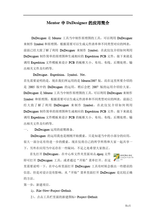
Mentor中DxDesigner的应用简介DxDesigner是Mentor工具当中制作原理图的工具,可以利用DxDesigner 来制作Symbol和原理图,根据需要可以生成元件清单和不同类型对应的网表,前面已经大致了解了利用DxDesigner来制作Symbol,在此仅仅介绍如何利用DxDesigner制作简单的原理图和生成相应的Expedition PCB文件,接下来就是调用Expedition文件模板来设计PCB的板框大小、布局、布线、后期处理、输出相关文件及归档等。
DxDesigne,Expedition,Symbol,Net。
首先需要说明的是,现在我们所运用的是Mentor2007版,而在这里所要介绍的是2005版中的DxDesigner的运用,稍后会把2007版的运用介绍给大家。
DxDesigner是Mentor工具当中制作原理图的工具,可以利用DxDesigner来制作Symbol和原理图,根据需要可以生成元件清单和不同类型对应的网表,前面已经大致了解了利用DxDesigner来制作Symbol,在此仅仅介绍如何利用DxDesigner制作简单的原理图和生成相应的Expedition PCB文件,接下来就是调用Expedition文件模板来设计PCB的板框大小、布局、布线、后期处理、输出相关文件及归档等。
一、DxDesigner运用的前期准备。
DxDesigner的运用我也是刚刚开始摸索,只是知道当中的小部分的应用,很大一部分还有待进一步的摸索,现在仅将自己的所学所得和大家一起共享一下,另外在应用当中还存在一些疑问,不足之处希望大家指正。
首先打开DxDesigner,在中心库文件夹里面双击.dproj文件即可打开DxDesigner工具,或者通过“开始”菜单打开。
在这里需要说明一下,在中心库里面打开DxDesigner工具有时候会报出一些错误的信息,但是对设计没有影响,从“开始”菜单里面打开DxDesigner是比较正确的方法。
SERVICE PARTS LISTˈR407C Application˅YBWC˄Design Level AFOR WUXI FACTORY PRODUCTS ONLYTABLE OF CONTENTS NOMENCLATURE (2)MAIN COMPONENTS (2)UNIT COMPONENTS (2)PIPING SYSTEM (3)PIPING SYSTEM (YBWC80A) (3)PIPING SYSTEM (YBWC100A/110A) (3)PIPING SYSTEM (YBWC135A) (4)PIPING SYSTEM (YBWC155A) (4)PIPING SYSTEM (YBWC170A) (4)PIPING SYSTEM (YBWC200A/240A).......................................... (5)CONTROL SYSTEM COMPONENTS (6)NEOPRENE (6)FLOW SWITCH (6)FIGURE (7)NOMENCLATUREMAIN COMPONENTSUNITS COOLER CODECONDENSERCODE COMPRESSORCODEPANEL CODEQUAN/ UNIT YBWC80A075W59171-000 075W59181-000 064W50935-015 371W04301-2011 YBWC100A 075W59172-000 075W59182-000 064W50935-016 1 YBWC110A 075W59173-000 075W59183-000 064W50935-016 371W04301-202 1 YBWC135A 075W59174-000 075W59184-000 064W50935-017 1 YBWC155A 075W59175-000 075W59185-000 064W50935-018371W04301-2031 YBWC170A 075W59176-000 075W59186-000 064W50935-019 371W04301-204 1 YBWC200A 075W59178-000 075W59188-000 064W50935-020 371W04301-205 1 YBWC240A 075W59180-000 075W59190-000 064W50935-021 371W04301-206 1OIL AND RREFRIGERANT CHARGE QUANTITYOILRREFRIGERANT MODELOILNAMEPART NUMBER /L NAMEPART NUMBER /KgYBWC80A 12.9 51 YBWC100A 12.1 73 YBWC110A 12.1 85 YBWC135A 14.4102YBWC155A 119YBWC170A 18.4132 YBWC200A 162YBWC240AJ1011W01003-000 22.3R407C 011W00325-000179POWER SUPPLY; 50UNIT COMPONENTSITEMNO DESCTIPTION PART NUMBER QUAN/UNIT REF.FIG1 BALL VALVE 7/8-14UNFX1/2NPT 022W01374-0002 FIG.12 SEAL O-RING NEOPRENE 028-12961-005 2 FIG.13 SAFTY VALVE 022W09505-000 2 FIG.14 ANGLE VALVE 022W09573-000 1 FIG.15 GASKET FLA 3/4 OD TUBE 028W09211-000 1 FIG.16 ¾” OD TUBE 023W00984-000 1 FIG.17 GASKET SEAL 1 O.D. X7/8028-04836-000 1 FIG.18 SENSOR TEMP. WELL075W33815-000 2 FIG.1 PIPING SYSTEM COMPONENTSPIPING SYSTEM COMPONENTS (YBWC80A)ITEMNO DESCTIPTION PART NUMBER QUAN/UNIT REF.FIG1 ANGLE VALVE 1-3/8” 022W09778-000 1 FIG.2_(a)2 DRY FILTER SHELL 1-3/8” 026W16960-002 1 FIG.2_(a)3 CORE FILTER DRIER 026W18328-000 3 FIG.2_(a)4 CAP INDICTOR MOIST 026-32800-000 1 FIG.2_(a)5 INDICTOR MOIST 1-3/8" 026W32398-000 1 FIG.2_(a) 67 SOLENOID VALVE DN 32 022W10820-000 1 FIG.2_(a)8 ANGLE VALVE 1/4" 022W00009-000 1 FIG.2_(a)9 EXPANSION VALVE 70TR/90TR 025-00088-000 1 FIG.2_(a)PIPING SYSTEM COMPONENTS (YBWC100A/YBWC110A)ITEMNO DESCTIPTION PART NUMBER QUAN/UNIT REF.FIG1 ANGLE VALVE 1-5/8” 022W09779-000 1 FIG.2_(a)2 DRY FILTER SHELL 1-5/8” 026W16960-000 1 FIG.2_(a)3 CORE FILTER DRIER 026W18328-000 3 FIG.2_(a)4 CAP INDICTOR MOIST 026-32800-000 1 FIG.2_(a)5 INDICTOR MOIST 1-5/8" 026W32399-000 1 FIG.2_(a) 67 SOLENOID VALVE DN 32 022W10820-000 1 FIG.2_(a) 8 ANGLE VALVE 1/4" 022W00009-000 1 FIG.2_(a)Danfoss TEX55 Valve Body 067G4001 022-11046-000 1EXPANSION VALVE (R407C) 067G3240 025-00090-000 19ORIFICE PLATE/TEX NO.2 067G2006 022-10962-007 1FIG.2_(a)PIPING SYSTEM COMPONENTS (YBWC135A)ITEMNO DESCTIPTION PART NUMBER QUAN/UNIT REF.FIG1 ANGLE VALVE 1-5/8” 022W09779-000 1 FIG.2_(a)2 DRY FILTER SHELL 1-5/8” 026W16960-000 1 FIG.2_(a)3 CORE FILTER DRIER 026W18328-000 3 FIG.2_(a)4 CAP INDICTOR MOIST 026-32800-000 1 FIG.2_(a)5 INDICTOR MOIST 1-5/8" 026W32399-000 1 FIG.2_(a) 67 SOLENOID VALVE DN 25 022W10819-000 1 FIG.2_(a)8 ANGLE VALVE 1/4" 022W00009-000 1 FIG.2_(a)9 EXPANSION VALVE (R407C) 50TR 025-00089-000 1 FIG.2_(a) 1011 SOLENOID VALVE DN 25 022W10819-000 1 FIG.2_(b) 12 EXPANSION VALVE (R407C) 70TR/90TR 025-00088-000 1 FIG.2_(b)PIPING SYSTEM COMPONENTS (YBWC155A)ITEMNO DESCTIPTION PART NUMBER QUAN/UNIT REF.FIG1 ANGLE VALVE 1-5/8” 022W09779-000 1 FIG.2_(a)2 DRY FILTER SHELL 1-5/8” 026W16960-000 1 FIG.2_(a)3 CORE FILTER DRIER 026W18328-000 3 FIG.2_(a)4 CAP INDICTOR MOIST 026-32800-000 1 FIG.2_(a)5 INDICTOR MOIST 1-5/8" 026W32399-000 1 FIG.2_(a) 67 SOLENOID VALVE DN 32 022W10820-000 1 FIG.2_(a)8 ANGLE VALVE 1/4" 022W00009-000 1 FIG.2_(a)9 EXPANSION VALVE (R407C) 70TR/90TR 025-00088-000 1 FIG.2_(a) 1011 SOLENOID VALVE DN 32 022W10820-000 1 FIG.2_(b) 12 EXPANSION VALVE (R407C) 70TR/90TR 025-00088-000 1 FIG.2_(b)PIPING SYSTEM COMPONENTS (YBWC170A)ITEMNO DESCTIPTION PART NUMBER QUAN/UNIT REF.FIG1 ANGLE VALVE 1-5/8” 022W09779-000 1 FIG.2_(a)2 DRY FILTER SHELL 1-5/8” 026W16960-000 1 FIG.2_(a)3 CORE FILTER DRIER 026W18328-000 3 FIG.2_(a)4 CAP INDICTOR MOIST 026-32800-000 1 FIG.2_(a)5 INDICTOR MOIST 1-5/8" 026W32399-000 1 FIG.2_(a) 67 SOLENOID VALVE DN 32 022W10820-000 1 FIG.2_(a)8 ANGLE VALVE 1/4" 022W00009-000 1 FIG.2_(a)9 EXPANSION VALVE (R407C) 70TR/90TR 025-00088-000 1 FIG.2_(a) 1011 SOLENOID VALVE DN 32 022W10820-000 1 FIG.2_(b) 12 EXPANSION VALVE (R407C) 70TR/90TR 025-00088-000 1 FIG.2_(b)PIPING SYSTEM COMPONENTS (YBWC200A)ITEMNO DESCTIPTION PART NUMBER QUAN/UNIT REF.FIG1 ANGLE VALVE 2-1/8” 022W10916-000 1 FIG.2_(a)2 DRY FILTER SHELL 2-1/8” 026W36858-000 1 FIG.2_(a)3 CORE FILTER DRIER 026W18328-000 3 FIG.2_(a)4 CAP INDICTOR MOIST 026-32800-000 1 FIG.2_(a)5 INDICTOR MOIST 1-5/8" 026W32399-000 1 FIG.2_(a) 67 SOLENOID VALVE DN 32 022W10820-000 1 FIG.2_(a)8 ANGLE VALVE 1/4" 022W00009-000 1 FIG.2_(a)ORIFICE PLATE /TEX NO.2 067G2006 022-10962-007 1Danfoss TEX55 Valve Body 067G4001 022-11046-000 1 9EXPANSION VALVE (R407C) 067G3240 025-00090-000 1FIG.2_(a)1011 SOLENOID VALVE DN 32 022W10820-000 1 FIG.2_(b) ORIFICE PLATE /TEX NO.2 067G2006 022-10962-007 1 FIG.2_(b)Danfoss TEX55 Valve Body 067G4001 022-11046-000 1 FIG.2_(b) 12EXPANSION VALVE (R407C) 067G3240 025-00090-000 1 FIG.2_(b)PIPING SYSTEM COMPONENTS (YBWC240A)ITEMNO DESCTIPTION PART NUMBER QUAN/UNIT REF.FIG1 ANGLE VALVE 2-1/8” 022W10916-000 1 FIG.2_(a)2 DRY FILTER SHELL 2-1/8” 026W36858-000 1 FIG.2_(a)3 CORE FILTER DRIER 026W18328-000 3 FIG.2_(a)4 CAP INDICTOR MOIST 026-32800-000 1 FIG.2_(a)5 INDICTOR MOIST 1-5/8" 026W32399-000 1 FIG.2_(a) 67 SOLENOID VALVE DN 32 022W10820-000 1 FIG.2_(a)8 ANGLE VALVE 1/4" 022W00009-000 1 FIG.2_(a)9 EXPANSION VALVE PHT85/4 375W69751-000 1 FIG.2_(a) 1011 SOLENOID VALVE DN 32 022W10820-000 1 FIG.2_(b) 12 EXPANSION VALVE PHT85/4 375W69751-000 1 FIG.2_(b)CONTROL SYSTEM COMPONENTSITEMNO DESCTIPTION PART NUMBER QUAN/UNIT REF.FIG1 SENSOR TEMP. 3M(GOLDAIR) 024W33670-000 3 FIG.32 SENSOR TEMP. 6M(GOLDAIR) 024W33671-0003 FIG.33 YBWC YK213T MAINBOARD 024W33656-000 14 YBWC HMI MICS-001 024W33657-000 1NEOPRENEUNITS CODE WEIGHT(Kg) PART NUMBER YBWC80A 2600YBWC100A 2700YBWC110A 2800YBWC135A 3100028W14462-000 YBWC155A 3300YBWC170A 3700YBWC200A 4200YBWC240A 4700FLOW SWITCHPART NUMBER DWP MODEL 024W26116-000 150 F61KB-11CFIG.1FIG.2_ (a)FIG.2_ (b)FIG.3COMPONENTS IN CONTROL PANEL(YBWC80AS~110AS)Item Name in Chinese Part Name in English P/N Qty.1 Main contactor 024W33658-000 22 contactor 024W33659-040 13 QF circuit Breaker 024W33660-000 14 Phase Sequence Protector 024W33661-000 15 Timer Relay 024W33662-000 16 Thermal Relay 024W33663-000 17 PLC MAIN BOARD 024W33656-000 18 QF circuit Breaker 024W33664-000 19 High Press Meter/Oil Press Meter 024W33665-000 210 Low Press Meter 024W33666-000 111 High & Low Pressure Switch 024W33667-000 112 Oil Pressure Differential 024W33675-000 113 Emergency Button 024W33668-000 114 Misc Controller 024W33657-000 115 Blue Light 024W33672-000 116 Yellow Light 024W33672-001 117 Green Light 024W33672-002 118 Red Light 024W33672-003 119 Switch 024W33673-000 120 CPU BATTERY FOR PLC(YBWC) 024W33674-000 121 Surge suppressers 024W33727-000 8 (YBWC135AS~155AS)Item Name in Chinese Part Name in English P/N Qty.1 Main contactor 024W33658-010 22 contactor 024W33659-020 13 QF circuit Breaker 024W33660-010 14 Phase Sequence Protector 024W33661-000 15 Timer Relay 024W33662-000 16 Thermal Relay 024W33663-010 17 PLC MAIN BOARD 024W33656-000 18 QF circuit Breaker 024W33664-000 19 High Press Meter/Oil Press Meter 024W33665-000 210 Low Press Meter 024W33666-000 111 High&Low Pressure Switch 024W33667-000 112 Oil Pressure Differential 024W33675-000 113 Emergency Button 024W33668-000 114 Misc Cotroller 024W33657-000 115 Blue Light 024W33672-000 116 Yellow Light 024W33672-001 117 Green Light 024W33672-002 118 Red Light 024W33672-003 119 Switch 024W33673-000 120 CPU BATTERY FOR PLC(YBWC) 024W33674-000 121 Surge suppressers 024W33727-000 8 YBWC170ASItem Name in Chinese Part Name in English P/N Qty.1 Main contactor 024W33658-020 22 contactor 024W33659-030 13 QF circuit Breaker 024W33660-010 14 Phase Sequence Protector 024W33661-000 15 Timer Relay 024W33662-000 16 Thermal Relay 024W33663-010 17 PLC MAIN BOARD 024W33656-000 18 QF circuit Breaker 024W33664-000 19 High Press Meter/Oil Press Meter 024W33665-000 210 Low Press Meter 024W33666-000 111 High&Low Pressure Switch 024W33667-000 11012 Oil Pressure Differential 024W33675-000 1 13 Emergency Button 024W33668-000 1 14 Misc Cotroller 024W33657-000 1 15 Blue Light 024W33672-000 1 16 Yellow Light 024W33672-001 1 17 Green Light 024W33672-002 1 18 Red Light 024W33672-003 1 19 Switch024W33673-000 120 CPUBATTERY FOR PLC(YBWC)024W33674-000 121Surge suppressers024W33727-0008(YBWC200AS~240AS)Item Name in Chinese Part Name in English P/N Qty. 1 Main contactor 024W33658-030 2 2 contactor 024W33658-010 1 3 QF circuit Breaker 024W33660-030 1 4 Phase Sequence Protector024W33661-000 1 5 Timer Relay 024W33662-000 1 6 Thermal Relay 024W33663-030 1 7PLC MAIN BOARD 024W33656-000 1 8QF circuit Breaker024W33664-000 1 9 High Press Meter/Oil Press Meter024W33665-000 2 10 Low Press Meter 024W33666-000 1 11 High&Low Pressure Switch 024W33667-000 1 12 Oil Pressure Differential 024W33675-000 1 13 Emergency Button 024W33668-000 1 14 Misc Cotroller 024W33657-000 1 15 Blue Light 024W33672-000 1 16 Yellow Light 024W33672-001 1 17 Green Light 024W33672-002 1 18 Red Light 024W33672-003 1 19 Switch024W33673-000 120 CPUBATTERY FOR PLC(YBWC)024W33674-000 121Surge suppressers024W33727-0008。
G9000 SERIESMMS KITINSTALLATION MANUAL480/480 V 1000/1330/1500/1660/2000kVADocument No.: 200150-001Document: 4GBH0153 Rev. BMarch 2020IMPORTANT NOTICENever attempt to install, operate, maintain or dispose of this equipment until you have first read and understood all of the relevant product warnings and user directions that are contained in this Installation manual.The installation of this equipment must only be performed by qualified personnel.The Instructions contained in this manual are not intended to cover all of the details or variations in equipment or to provide for every possible contingency to be met in connection with installation, operation, or maintenance. Should further information be required or should particular problems arise which are not covered sufficiently the matter should be referred to the local TOSHIBA sales office.Nothing in this manual shall alter Toshiba International Corporation’s s tandard terms and conditions or the conditions of any written sales contract.Any Electrical or mechanical modifications to this equipment without prior written consent of TOSHIBA will void all warranties and may void UL/CUL listing. Unauthorized modifications may also result in personal injury, death, or equipment damage.UNINTERRUPTIBLE POWER SYSTEMIf additional information or technical assistance is required call TOSHIBA Customer Support Center at (877) 867-8773, or write to: Toshiba International Corporation, 13131 West Little York Road, Houston, TX 77041-9990 Attn: UPS Product Manager.Keep this manual with the UPS equipment.Job Number:Model Number:Serial Number:Application:Shipping Date:Date of Installation:Inspected By:Purpose and Scope of ManualThis manual provides information on how to safely install, operate, and maintain your TOSHIBA power electronics product. This manual includes a section on General Safety Instructions that describes the warning labels and symbols that are used throughout the manual. Read the manual completely before installing, operating, or performing maintenance on this equipment.This manual and the accompanying drawings should be considered a permanent part of the equipment and should be readily available for reference and review. Dimensions shown in the manual are in metric and/or the Imperial equivalent.TOSHIBA reserves the right, without prior notice, to update information, make product changes, or to discontinue any product or service identified in this publication.TOSHIBA is a registered trademark of TOSHIBA INTERNATIONAL CORPORATION. All other product or trade references appearing in this manual are registered trademarks of their respective owners.TOSHIBA shall not be liable for technical or editorial omissions or mistakes in this manual. Nor shall it be liable for incidental or consequential damages resulting from the use of information contained in this manual.This manual is copyrighted. No part of this manual may be photocopied or reproduced in any form without the prior written consent of TOSHIBA INTERNATIONAL CORPORATION.© Copyright 2020 TOSHIBA INTERNATIONAL CORPORATIONAll rights reserved.Printed in JapanContacting TOSHIBA Customer Support CenterThe TOSHIBA Customer Support Center can be contacted to obtain help in resolving any Uninterruptible Power System problem that you may experience or to provide after sales service support.Toshiba Customer Support Center8 a.m. to 5 p.m. (CST) – Monday through FridayTel (877) 867-8773Fax (713) 896-5212E-mail –**************************You may contact TOSHIBA by writing to:TOSHIBA INTERNATIONAL CORPORATION.SOCIAL INFRASTRUCTURE SYSTEMS GROUPPOWER ELECTRONICS DIVISION13131 West Little York Rd.Houston, TX 77041-9990Attn: UPS Product ManagerFor further information on Toshiba products and services, please visit our website at:/Table of ContentsTable of Contents ................................................................................................................................................................ i ii List of Tables ....................................................................................................................................................................... i ii List of Figures ...................................................................................................................................................................... i ii 1How to use this Manual .. (1)1.1Notice Icons (1)1.2Qualified Personnel (2)2OVERVIEW (3)3MMS KIT Parts List (4)4Installation Procedures (6)5Parallel Operation System Connection (12)List of TablesTable 2-1: Parts List of MMS KIT (4)Table 3-1: Dip Switch Setting on Parallel Interface Board (IFAU-16*) (10)Table 3-2: Status of Jumpers on Parallel Interface Board(IFAU-16*) (11)List of FiguresFigure 1-1: Parallel-Connection between UPSs (3)Figure 2-1: MMS KIT Parts Identification (5)Figure 3-1: Location of IFAU-16* MMS PCB Installation (1000kVA) (6)Figure 3-2: Location of IFAU-16* MMS PCB Installation (1330-2000kVA) (7)Figure 3-3: Cable Connections Between IFAU-16* and Others (8)Figure 3-4: Example of the Inside of Bypass Cabinet after Installation (1000kVA) (9)Figure 3-5: Dip Switch Location on Parallel Interface Board (IFAU-16*) (10)Figure 3-6: Example of Dip Switch Setting (10)Figure 3-7: Location of Jumpers on Parallel Interface Board(IFAU-16*) (11)Figure 4-1: Diagram of Power Wire Connections (Parallel Operation System) (12)Figure 4-2: Diagram of Power Wire and Control Wire Connection (Parallel Operation System) (13)Figure 4-3: UPS Module Parallel Interface Board (IFAU-16*) Interconnections (14)This Page Left Intentionally Blank1 How to use this ManualThis manual is designed for ease of use, giving the user easy and quick reference to information.This manual uses notice icons to draw attention to the user important information regarding the safe operation and installation of the UPS.1.1 Notice IconsThe notice icons used in this manual are explained below, and should be taken into account and adhered to whenever they appear in the text of this manual.Warning: A warning symbol shows potentially hazardous situation or condition which could result in personal injury or death, if not avoided.Caution: A caution symbol shows potentially hazardous situation or condition which could result in personal injury or equipment damage, if not avoided.Note: A Note symbol shows the information the user or the service personnel should observe during the UPS operation or service work. Prohibit: A prohibit symbol shows the act the user or the service personnel should NEVER perform during the UPS installation, operation or service work.Safety Recommendations: If any problems are encountered while following this manual, contact the Toshiba Customer Support Center.WARNINGCAUTION!NOTEPROHIBIT1.2 Qualified PersonnelOnly qualified persons are to install, operate or service this equipment according to all applicable codes and established safety practices.A qualified person must:1) Read this entire instruction manual carefully.2) Be skilled in the installation, construction or operation of the equipment and aware of the hazards involved.3) Be trained and authorized to safely energize, de-energize, clear, ground, lockout and tag circuits in accordancewith established safety practices4) Be trained and authorized to perform the service, maintenance or repair of this equipment5) Be trained in the proper care and use of protective equipment such as rubber gloves, hard hat, safety glasses,face shield, flash clothing, etc. in accordance with established practices6) Be trained in rendering first aid.2 OVERVIEWTOSHIBA G9000 Uninterruptible Power Supply Systems (UPS) need an MMS KIT whenever two or more UPSs are installed in parallel operation configuration.Each UPS requires an MMS KIT installed to allow it to complete the communication circuit with other modules.All UPSs must be de-energized when the MMS KITs are installed and the parallelinterconnections are established between the modules.CAUTIONUPS-1MMSKITUPS-2MMSKITUPS-nMMSKITFigure 2-1: Parallel-Connection between UPSs3 MMS KIT Parts ListTable 3-1: Parts List of MMS KITPart # Part name Qty Remarks1 Parallel Interface board: IFAU-16* (IF3) 12 Cable: CN95 (IFAU-16* - UPJR-D*) 1 1865mmHIF3-20D - HIF3-20D3A Cable: CN94 (IFAU-16* - UPJR-D*) 1 1820mm, J-10P - J-8P 3B Cable: CN96 (IFAU-16* - CSAU-07*) 1 1180mm, J-16P - J-16P 3C Wire: IFAU-16* GNDB(M3 clamp) - Ground bus bar (M4 clamp) 1 1170mm, Green3D Wire: IFAU-16* GNDC(M3 clamp) - Ground bus bar (M4 clamp) 1 1220mm, Green3E Wire: IFAU-16* GNDD(M3 clamp) - Ground bus bar (M4 clamp) 1 1070mm, Green4 Spacer: SQ-14(MBB-314) 85 Ferrite Core: E2530MRC 16 Dust Cover for LAN Jack: LD-DUSTBK6 12 6pcs/pack x 27 Screws (M3) 88 Spring washers (M3) 89 Flat washers (M3) 810 Screws (M4) 111 Cable Tie (T30R) 18 Use as necessary12 Cable Tie (T50R) 2 Use as necessary13 Base (ABMM-A-D) 15 Use as necessaryPart #1: Parallel Interface board (IFAU-16*) Part #2: CablePart #3A, 3B: Cable Part #3C, 3D, 3E: WirePart #5: Ferrite CorePart #4: SpacerPart #6: Dust Cover for LAN Jack Part #7: Screw(M3), Part #10:Screw(M4)Figure 3-1: MMS KIT Parts Identification4 Installation ProceduresFigure 4-1: Location of IFAU-16* MMS PCB Installation (1000kVA)Details of AFront View of bypass cabinet (with door open)IFAU-16*Screw(M3) x8(Upper right of bypass cabinet for 1000kVA UPS ) Step1 Step 1: Screw 8 spacers on the metallic plate (shown in red). Step 2: Secure the parallel interface board IFAU-16* on the spacerswith M3 screws.Step 3: Secure the ferrite core with an M3 screw (shown in pink). Step 4: Cover the modular connectors with the dust cover. Step 5A: Check location of Ground bus for the next step.Step2Step3Step4Spacer x8Dust cover x12Ferrite core Screw(M3) Unit: mm(Front cover)(Front cover)Ground busStep5ADetailsFigure 4-2: Location of IFAU-16* MMS PCB Installation (1330-2000kVA)Front View of bypass cabinet (with door open)Details of AIFAU-16*Screw(M3) x8(Upper right of bypass cabinet for 1330-2000kVA UPS ) Step 1: Screw 8 spacers on the metallic plate (shown in red). Step 2: Secure the parallel interface board IFAU-16* on the spacerswith M3 screws.Step 3: Secure the ferrite core with an M3 screw (shown in pink). Step 4: Cover the modular connectors with the dust cover. Step 5A: Check location of Ground bus for the next step.Step3Ferrite core Screw(M3)Unit: mmStep5ADetailsStep2Ground busSpacer x8Dust cover x12Step1Step4Figure 4-4: Example of the Inside of Bypass Cabinet after Installation (1000kVA)IMPORTANT NOTICEIn cases where there are large amounts of slack LAN cables after installation: Keep cables away from the power conversion circuits and conductorsin order to avoid interference in the parallel control communication. Do not roll cables as doing so may cause signal interference.PROHIBITIFAU-16*Parallel interface boardCSAU-07*Sensor board (Behind this panel)Ground BusExample of 1000kVAUPJR-D*Main control boardIFAU-16*Figure 4-5: Dip Switch Location on Parallel Interface Board (IFAU-16*)Table 4-1: Dip Switch Setting on Parallel Interface Board (IFAU-16*) System No.1 UPSNo.2 UPSNo.3 UPSNo.4 UPSNo.5 UPSNo.6 UPS2 by MMS All ON 1 and 2: ON3 to 8: OFF3 by MMS All ON All OFF 1 & 2: ON 3 to 8: OFF4 by MMS All ON All OFF All OFF 1 & 2: ON 3 to 8: OFF5 by MMS All ON All OFF All OFF All OFF 1 & 2: ON 3 to 8: OFF6 by MMSAll ONAll OFFAll OFFAll OFFAll OFF1 & 2: ON 3 to 8: OFFFigure 4-6: Example of Dip Switch SettingStep 8: Setup the dip switch on IFAU-16* according to Table 4-1.UPS#1 1 to 8: ON (All ON)UPS#2 ~ UPS#(N-1)1 to 8: OFF (All OFF)UPS#N 1 and 2: ON 3 to 8: OFFDip Switch(S1)Step 9: Make sure the status of Jumpers on IFAU-16* according to Table 4-2.JP1SHORT SHORTOPENFigure 4-7: Location of Jumpers on Parallel Interface Board(IFAU-16*)Table 4-2: Status of Jumpers on Parallel Interface Board(IFAU-16*)# Device Status1 JP1 SHORT2 JP6 SHORT3 JP11 OPENSOCIAL INFRASTRUCTURE SYSTEMS GROUPPOWER ELECTRONICS DIVISION13131 West Little York Rd., Houston, TX 77041Tel: 855-803-7087 Fax 713-896-5212US 800/231-1412 Canada 800/872-2192 Mexico 01/800/527-1204 Printed in Japan。