萨特科技贴片保险丝规格书
- 格式:doc
- 大小:22.13 MB
- 文档页数:46
天津市航空易思维科技有限公司
贴片保险丝选型方法
2013/6/28
本文档的目的1)了解贴片保险丝参数2)能够根据本方法进行贴片保险丝选型3)本文档不限于贴片保险丝
更新说明
目录
一、保险丝的参数 (4)
二、保险丝选型流程 (4)
1、稳态参数 (4)
2、瞬态参数 (5)
3、安规要求 (5)
4、最终裕量 (5)
三、保险丝选型示例 (5)
1、电路参数要求 (5)
2、设计过程 (5)
附录1 华巨温度折减曲线 (7)
附录2几种常见脉冲电流热熔值计算 (7)
附录3 华巨产品目录中的I2t vs t曲线 (8)
贴片保险丝选型方法
一、保险丝的参数
表1 保险丝参数
二、保险丝选型流程
1、稳态参数
1)额定电流和工作电流:In >= I/75%
2)根据工作温度进行温度折减:In >= I/75%/K
2、瞬态参数
1)根据附录2计算脉冲电流I2t
2)根据附录2进行脉冲折减
3)根据附录2进行脉冲折减部分的温度折减
4)确定可耐受脉冲冲击次数的保险丝最小的电流值。
3、安规要求
ICE安规规定:保险丝不折减
UL安规规定:保险丝折减率为75%
4、最终裕量
考虑到电路中元件参数波动会导致电流波动,在符合设计上下限要求的前提下,建议预留30%的设计裕量。
三、保险丝选型示例
1、电路参数要求
2、设计过程
附录1 华巨温度折减曲线
附录2几种常见脉冲电流热熔值计算
脉冲温度折减系数
附录3 华巨产品目录中的I2t vs t 曲线。
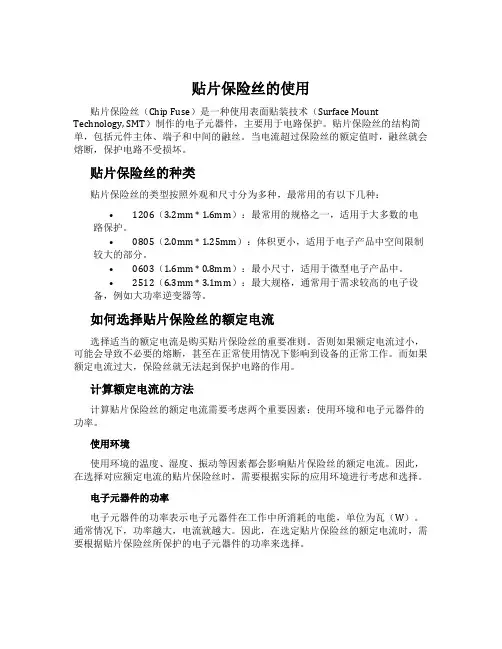
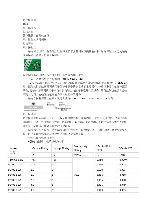
贴片保险丝的使用贴片保险丝(Chip Fuse)是一种使用表面贴装技术(Surface Mount Technology, SMT)制作的电子元器件,主要用于电路保护。
贴片保险丝的结构简单,包括元件主体、端子和中间的融丝。
当电流超过保险丝的额定值时,融丝就会熔断,保护电路不受损坏。
贴片保险丝的种类贴片保险丝的类型按照外观和尺寸分为多种,最常用的有以下几种:•1206(3.2mm * 1.6mm):最常用的规格之一,适用于大多数的电路保护。
•0805(2.0mm * 1.25mm):体积更小,适用于电子产品中空间限制较大的部分。
•0603(1.6mm * 0.8mm):最小尺寸,适用于微型电子产品中。
•2512(6.3mm * 3.1mm):最大规格,通常用于需求较高的电子设备,例如大功率逆变器等。
如何选择贴片保险丝的额定电流选择适当的额定电流是购买贴片保险丝的重要准则。
否则如果额定电流过小,可能会导致不必要的熔断,甚至在正常使用情况下影响到设备的正常工作。
而如果额定电流过大,保险丝就无法起到保护电路的作用。
计算额定电流的方法计算贴片保险丝的额定电流需要考虑两个重要因素:使用环境和电子元器件的功率。
使用环境使用环境的温度、湿度、振动等因素都会影响贴片保险丝的额定电流。
因此,在选择对应额定电流的贴片保险丝时,需要根据实际的应用环境进行考虑和选择。
电子元器件的功率电子元器件的功率表示电子元器件在工作中所消耗的电能,单位为瓦(W)。
通常情况下,功率越大,电流就越大。
因此,在选定贴片保险丝的额定电流时,需要根据贴片保险丝所保护的电子元器件的功率来选择。
参考值以下参考表格提供了常见尺寸的贴片保险丝的额定电流范围:尺寸额定电流范围1206 0.1A ~ 15A0805 0.05A ~ 8A0603 0.05A ~ 2A2512 0.1A ~ 30A在实际选择贴片保险丝的额定电流时,可以参考以上表格作为基础值,结合使用环境和电子元器件的功率进行综合考虑和选择。
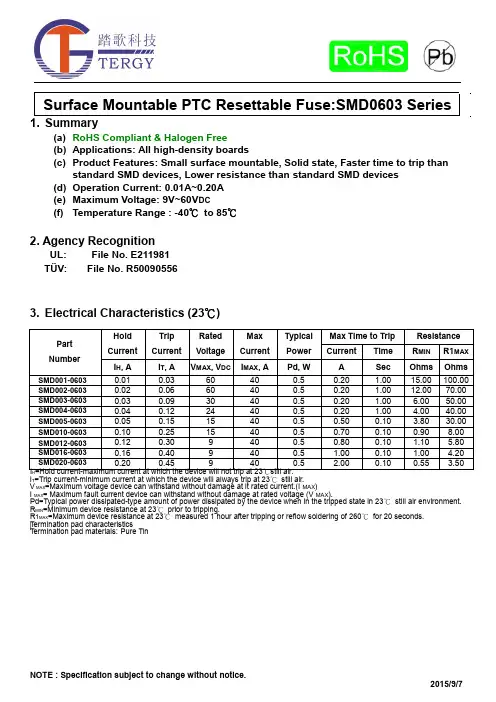
(a) RoHS Compliant & Halogen Free(b) Applications: All high-density boards(c) Product Features: Small surface mountable, Solid state, Faster time to trip thanstandard SMD devices, Lower resistance than standard SMD devices(d) Operation Current: 0.01A~0.20A(e) Maximum Voltage: 9V~60V DC(f) Temperature Range : -40℃to 85℃2. Agency RecognitionUL: File No. E211981TÜV: File No. R500905563. Electrical Characteristics (23℃)HI T=Trip current-minimum current at which the device will always trip at 23℃still air.V MAX=Maximum voltage device can withstand without damage at it rated current.(I MAX)I MAX= Maximum fault current device can withstand without damage at rated voltage (V MAX).Pd=Typical power dissipated-type amount of power dissipated by the device when in the tripped state in 23℃still air environment. R MIN=Minimum device resistance at 23℃prior to tripping.R1MAX=Maximum device resistance at 23℃measured 1 hour after tripping or reflow soldering of 260℃for 20 seconds. Termination pad characteristicsTermination pad materials:Pure Tin4. SMD Product Dimensions (Millimeters)5. Thermal Derating Curve6. Typical Time-To-Trip at 23℃7. Material SpecificationTerminal pad material: Pure TinSoldering characteristics: Meets EIA specification RS 186-9E, ANSI/J-std-002 Category 38. Part Numbering and Marking SystemPart Numbering System Part Marking SystemS M D □ □ □ – 0603Current RatingExampleWarning: -Operation beyond the specified maximum ratings or improper use may result in damage and possibleelectrical arcing and/or flame.-PPTC device are intended for occasional overcurrent protection. Application for repeated overcurrent condition and/or prolonged trip are not anticipated. 甲、 -Avoid contact of PPTC device with chemical solvent. Prolonged contact will damage the deviceperformance.AB=C=D=E=F=G=H=I= X=Y=Z=A=B=F=G==SMD001-0603SMD002-0603SMD003-0603SMD004-0603SMD005-0603SMD010-0603SMD012-0603SMD016-0603SMD020-0603SMD001-0603SMD002-0603SMD003-0603SMD004-0603SMD005-0603SMD010-0603SMD012-0603SMD016-0603SMD020-06039. Pad Layouts 、Solder Reflow and Rework RecommendationsThe dimension in the table below provide the recommended pad layout for each SMD 0603 deviceNote 1: All temperatures refer to of the package,measured on the package body surface.Reflow Profile。
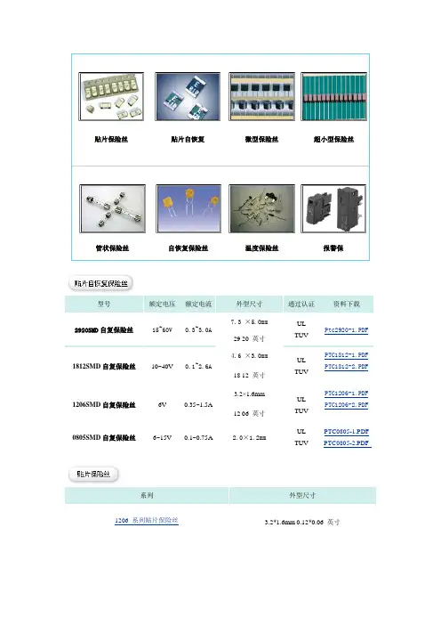
型号额定电压 额定电流外型尺寸 通过认证 资料下载2920SMD 自复保险丝15~60V0.3~3.0A7.3 ×5.0mmUL TUVPtc2920-1.PDF29 20 英寸 1812SMD 自复保险丝10~40V0.1~2.6A4.6 ×3.0mmUL TUVPTC1812-1.PDF PTC1812-2.PDF18 12 英寸 1206SMD 自复保险丝6V0.35~1.5A3.2×1.6mmUL TUV PTC1206-1.PDF PTC1206-2.PDF12 06 英寸0805SMD 自复保险丝6~15V0.1~0.75A2.0×1.2mmUL TUVPTC0805-1.PDF PTC0805-2.PDF系列外型尺寸1206 系列贴片保险丝3.2*1.6mm 0.12*0.06 英寸0603 系列贴片保险丝 1.6*0.8mm 0.06*0.03 英寸0402 系列贴片保险丝 1.0*0.5mm 0.01*0.005 英寸2410 系列贴片保险丝 6.8*2.7mm 0.24*0.10 英寸型号额定电压额定电流外型尺寸(mm)通过认证资料下载20N 速断型250V/125V 0.1∽20AΦ2.7*7.2 UL/CSA/PSE20N.pdf20T.pdf 20T 延时型250V/125V0.1∽7.0AΦ2.7*7.2 UL/CSA/PSEMCR.pdf MCR 速断型125V0.062∽10AΦ3.1*7.5UL/CSAR251 速断型125V0.062∽15AΦ2.4*7.2 UL/CSA r251-253.pdf型号额定电压额定电流外型尺寸(mm)通过认证资料下载SR5 圆柱型250V 1∽5A Φ8.4*7.6 UR/VDE/CCC SR5.pdfSS5.pdf SS5 方型250V1∽5A Φ8.6*7.6*4 UR/CCCmet.pdf MET 圆柱型250V0.04∽6.3AΦ8.4*7.6UR/VDE/CCCMST 方型250V0.04∽6.3AΦ8.6*7.6*4 UR/VDE/CCC mst.pdfU30系列自恢复保险丝 耐压 30VG16系列自恢复保险丝 耐压 16VS 系列自恢复保险丝 耐压 6-16V BR 系列自恢复保险丝 耐压 125V R250系列自恢复保险丝 耐压 250V原理说明 参数说明:保持电流(Ih ):25℃静止空气环境中不触发电阻突越的最高电流。
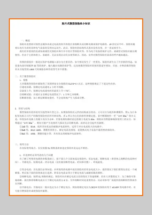
贴片式微型保险丝小知识一、概述保险丝是借助可熔性金属体内流过电流的焦耳热使自身熔断从而切断电路来保护电路的。
19世纪后半叶,保险丝随着以电灯为首的各种电气设备的发明应运而生,此后,保险丝的结构形式基本没有改变,并一直延续至今。
我们经常看到的是诸如玻璃管式保险丝和汽车中的片型保险丝等。
作为电子设备的保护元件,玻璃管式保险丝被长期使用,但由于它的体积大、易破碎、无法实现自动化安装等缺点,因此,业界对微型保险丝需求的呼声越来越高。
传统的保险丝一般是以保护电源输入部分为主要目的。
如今情况发生了一些变化,保险丝派生出了许多新的用途,如设备内部印制板和IC等的保护、输入输出电路的保护等,这也使微型保险丝的使用量逐年增加。
目前,市售的微型保险丝从引线型到1005尺码规格各种形状型号多不胜数。
二、关于微型保险丝1.规格大多数微型保险丝都取得了美国国家安全规格的UL248-14认证,这种规格规定了下述这些内容:①通电容量:按额定电流通电1小时不熔断。
②温度上升:按额定电流通电时的温度上升<75℃。
③熔断试验:在通以2倍额定电流情况下,1分钟之内熔断。
④断路容量:加上额定断路容量时,不会连续地产生飞弧或引燃。
2.形状与结构微型保险丝的形状有引线型和片型之分,如果按保险丝元件的结构来分的话,又可以分为线形和薄膜形。
图1为日本松尾电机公司生产的微型保险丝的外形和结构。
表1所示为它们的特性和额定值。
表中断路特性一栏“24V/50A”的含义是:即使加在电路上的最大电压为24V,并使电路短路时流过的最大电流为50A,保险丝仍然能够确保使用上的安全。
如果超过“24V/50A”,则有可能产生连续的飞弧而无法切断电路,或者还会引起外壳破裂。
①JAD型:3216,线形具有优良的耐脉冲电流特性,适用于冲击电流较大的电路中。
②KAB型:2012/1608,薄膜形体积小、额定电流范围宽,是便携式电子设备中最理想的保险丝。
③KAC型:1005,薄膜形超小型,具有优良的耐脉冲电流特性。
The SMD0603 Series PTC providessurface mount over-currentprotection for applications where space is at a premium and resettable protection is desired.u RoHS compliant, Lead-Free and Halogen-Free u Fast time-to-tripu Compact design saves board space u Low resistance uLow-profileu Mobile phones - battery and port protection u Game console port protection u USB peripherals u Disk driveu PDAS / digital cameras u Power ports uGeneral electronicsHold Current Trip Current Rated Voltage Max Current Typical Power Maximum TimeTo Trip Resistance Part NumberI hold (A)I trip (A) V max (Vdc) I max (A) P dtyp. (W) Current (A) Time (Sec.) R min (Ω) R 1max (Ω) SMD0603-010 0.10 0.30 15 40 0.5 0.50 1.00 0.90 6.00 SMD0603-020 0.20 0.50 9.0 40 0.5 1.00 0.60 0.55 3.50 SMD0603-025 0.25 0.55 9.0 40 0.5 8.00 0.80 0.50 3.00 SMD0603-035 0.35 0.75 6.0 40 0.5 8.00 0.10 0.20 1.40 SMD0603-050 0.50 1.00 6.0 40 0.5 8.00 0.10 0.10 0.80 SMD0603-075 0.75 1.50 6.0 40 0.5 8.00 0.10 0.06 0.45 SMD0603-100 1.00 2.00 6.0 40 0.5 8.00 0.10 0.04 0.30I hold = Hold current: maximum current device will pass without tripping in 23°C still air. I trip = Trip current: minimum current at which the device will trip in 23°C still air. V max = Maximum voltage device can withstand without damage at rated current (I max ) I max = Maximum fault current device can withstand without damage at rated voltage (V max ) P dtyp.= Power dissipated from device when in the tripped state at 23°C still air. R min = Minimum resistance of device in initial (un-soldered) state.R 1max = Maximum resistance of device at 23°C measured one hour after tripping.Caution: Operation beyond the speci fied rating may result in damage and possible arcing and flame.Profile FeaturePb-Free Assembly Average Ramp-Up Rate (T S max to T P ) 3°C/second max. Preheat :Temperature Min (T S min) Temperature Max (T S max) Time (T S min to T S max)150°C 200°C60-180 seconds Time maintained above: Temperature(TL) Time (tL)217°C60-150 seconds Peak/Classification Temperature(T P ): 260°C Time within 5°C of actual peak: Temperature20-40 seconds Ramp-down Rate:6°C/ second max. Time 25°C to Peak Temperature8 minutes max.Note: All temperatures refer to of the package, measured on the package body surface.Solder reflowDue to “Lead Free ” nature, Temperature and Dwelling time for the soldering zone is higher than those for Regular. This may cause damage to other components.1. Recommended max past thickness > 0.25mm.2. Devices can be cleaned using standard methods and aqueous solvent.3. Rework use standard industry practices.4. Storage Environment : < 30/ 60%RH ℃Caution:1. If reflow temperatures exceed the recommended profile, devices may not meet the performance requirements.2. Devices are not designed to be wave soldered to the bottom side of the board.Terminal pad material Pure TinSoldering CharacteristicsMeets EIA specification RS 186-9E, ANSI/J-std-002 Category 3hold Ambient Temperature (°C)A B C DeviceNominalNominal Nominal 0603 Series1.000.701.00Model-40℃-20℃0℃25℃40℃50℃60℃70℃85℃SMD0603-010 0.13 0.12 0.11 0.10 0.08 0.07 0.06 0.05 0.03 SMD0603-020 0.27 0.25 0.23 0.20 0.17 0.14 0.12 0.10 0.07 SMD0603-025 0.32 0.29 0.27 0.25 0.21 0.18 0.16 0.05 0.03 SMD0603-035 0.47 0.41 0.38 0.35 0.29 0.26 0.24 0.20 0.14 SMD0603-050 0.67 0.59 0.54 0.50 0.41 0.37 0.34 0.29 0.20 SMD0603-075 0.98 0.85 0.81 0.75 0.60 0.54 0.44 0.40 0.31 SMD0603-1001.301.121.081.00 0.800.720.580.530.42Maximum ambient operating temperature(Tmao) vs. hold current (I hold)flame.u PPTC device are intended for occasional over-current protection. Application for repeated over-current condition and/or prolonged trip are not anticipated.uAvoid contact of PPTC device with chemical solvent. Prolonged contact will damage the device performance.0.33 (8.4)0.512(13.0)Arbor Hole DiameterDimensions are in inches (and millimeters)0.157 (4.0) 0.059 (1.5)Diameter Cover tape(4.0)(5.4)。
DescriptionFeatures ApplicationElectrical Characteristcs06.000 Series06.000 Series are the fuses set the industry standard for performance, reliability and quality. The solder-free design provides excellent on-off and temperature cycling characteristics during use and also makes our SMD fuses more heat andshock tolerant than typical subminiature fuses..Rapid interruption of excessive current Compatible with reflow and wave solder Ceramic and glass construction One time positive disconnectLead free and Halogen free materialSecondary circuit protectio Laptop, notebook, netboo Flat panel displaysHigh definition television(HDTV)LCD/LED backlightingComputers and peripherals Gaming console systemsHandheld/portable equipment Mobile device chargesAutomotiveCentral body control moduleHeating ventilation and air conditioning Doors,window lift and seat control Digital instrument clusterIn-vehicle infotainment and navigation Electric pumps,motor control andPowertrain control module(PCU)/Engine Transimission Control Unit(TCU)Agency informationFile Number:E365879, Guide JDYX2/JDYX806.000 SeriesSpecificationNotes* DC Interrupting Rating (Measured at rated voltage, time constant of less than 50 microseconds, battery source)* DC Cold Resistance are measured at <10% of rated current in ambient temperature of 25 degrees * Typical Pre-arcing I²t are measured at 10In Current* For fuse below 1A, the color of glass coating is Blue; for 1A and above, it’s Green.Dimensions (Unit: mm/inch)PackageRated current06.000.2Fast Acting SMD Series Part Numbering System0.35±0.15Time -Current Curves06.000 Series1A1.5A2A2.5A 3A 3.5A 4A 5A6A7A 8ACurrent(Ampere)T i m e (S e c o n d )1010.10.00010.000010.0010.01110100Product CharacteristcsPackaging Dementions06.000 SeriesInstallation RecommendationsWave Soldering PaametersSolder Pot Temperature: 260°C maxSolder Dwell Time: 10Seconds maxReel Dementions (Unit:mm)。
Product CatalogNANJING SART SCIENCE & TECHNOLOGY DEVELOPMENT CO.,LTD Maqun Science & Technology Park, Qingma Road 6#, Nanjing, ChinaTel :+86-25-83241391Company IntroductionSART Technology﹐the first Chinese manufacturer of SMD fuse﹐was founded in 2006﹒SART has devoted itself to research and develop circuit protection devices ever since﹒SART’s facility in Nanjing are certified by TS16949, ISO 9001 and ISO14001﹒Our main products include SMD fuses and Current Sensing Resistors(CSR)﹒ Our SMD fuses have been widely used in different applications like LCD panels、battery packs、battery chargers、digital cameras、cell phones etc﹒SART ceramic 6125 fuses with raw material originated from Germany have the advantage of a higher breaking capacity﹐facilitating their use in circuits with higher current and voltage﹒Our current sensing resistors(CSR) have great competitive edge in terms of ultra low ohm﹐low TCR﹐tight tolerance﹐high withstanding surge current and low thermal EMF﹒They are designed for current detecting and can be perfectly utilized by intelligent Li-ion rechargeable batteries﹒With our mission in mind﹐SART has made huge investment in building a strong R&D team﹐a global sales team and an international management team to provide our best service to global customers﹒SART’s mission and commitment are ﹕S ervice: Global sales offices and on-time deliveryA ffordability: Best quality for best prices availableR ecognition: Win trust and award from major customersT echnology: Innovative technology for the marketYOU GIVE US AN OPPORTUNITY; WE PROMISE YOU THE FUTURE!Contents⏹Fuse Selection Guide (1)Square Ceramic Surface Mount Fuse⏹Fast Acting of S6125-F Series (5)Thick Film Surface Mount Fuse⏹Fast Acting of S0603-F Series (9)⏹Slow Blow of S0603-S Series (13)⏹Fast Acting of S1206-F Series (17)⏹Slow Blow of S1206-S Series (21)Current Sensing Surface Mount Resistor ⏹Thick Film of SK Series (25)●0603 of SK Series●0805 of SK Series●1206 of SK Series●1210 of SK Series●2010 of SK Series●2512 of SK Series⏹Metal Strip of SM Series (28)●1206 of SM Series●2512 of SM Series⏹Metal Foil of SMF Series (31)●0805 of SMF Series●1206 of SMF Series●2512 of SMF Series⏹Recommended Solder Pad Layout..34⏹Recommended IR-Reflow Profile (35)⏹Packaging (36)⏹Storage Condition (39)This selection guidelines and product data are intended to provide technical information that will help with selection of fuse. Since these are only a few of the contributing parameters, application testing is strongly recommended and should be used to verify performance in the application circuit.1. Fuse selection DescriptionDuring normal load conditions, the fuse must carry the normal operating current of the circuit without nuisance openings. However, when an overcurrent occurs the fuse must interrupt the overcurrent and withstand the voltage across the fuse after internal arcing. To properly select a fuse the following items must be considered:➢Application voltage (AC or DC)➢Normal operating current➢Ambient temperature➢Overload conditions and opening times➢Maximum available fault current➢Pulse (or Surge current, Inrush current, Start-up current) characteristics➢Physical size and available board space➢Standards requirements or environmental protection requestApplication Voltage:The voltage rating of the fuse must be greater than (or equal to) the maximum open circuit voltage Normal operating current: An operating current of 75% or less than rated current of fuse is recommended for operation at 25℃ to avoid nuisance openings.Ambient temperature:All electrical characteristics of fuse are rated and validated at an ambient temperature of 25℃.Both higher and lower ambient temperatures will affect the fuse’s opening and current carrying characteristics. Please refer to the temperature derating curve for individual product series found in the specifications.Overload conditions and opening times:Specific attention must be given to first overload operating points. For fuses, the first overload point is usually between 200% to 300% of rated current.Maximum available fault current:The interrupting rating of fuse must meet or greater than the maximum fault current of the circuit.Pulse current characteristics:Transient Pulse current is used to describe wave shapes that result from any start up, Inrush, Surge, or transient currents in a circuit. Electrical pulses produce thermal cycling and possible mechanical fatigue that could affect the life of the fuse. Initial or start-uppulses are normal for some applications and require the characteristic of a slow blow fuse. The fuse’s capability to withstand a surge pulse without causing thermal stress to the fuse element, which may result in nuisance openings, can be determined once the circuit’s pulse I 2t is calculated. The circuit designer nee ds to properly size the fuse so that the fuse’s melting I 2t value is greater than or equal to the pulse I 2t divide by a pulse factor Fp. In design the selected fuse should have a I 2t value much greater than the I 2t value of pulse. The I 2t value of a pulse can be approximated from the following formulas for a typical wave Shape, refer to P1.Physical size and available board space:Please refer to the product dimensions presented in Sartfuse product datasheet for specific information (such as 0603/1206/6125).Standards requirements or environmental protection request:Please refer to the product datasheet or contact us, we will supply specially service to you. 2. Flow for Fuse selectionStep1. Measurement of circuit values using actual device.Measure the circuit values, such as operating current, Inrush current waveform, Ambient temperature.Step2. Calculation from operating current. Rated current of fuse ≧Operating current/①/② ①Rated derating factor: 0.75②Temperature derating factor: (Look Temperature Derating Curve P1)Example: Operating current = 1.7A, Ambient temperature = 80 o CChoosing Rated current of fuse ≧ 1.7/0.75/0.91 = 2.491A(0.91:Temperature 80 o C derating factor)T e m pTemperature in degrees o CP1: Chip fuse Temperature Derating Curve2Fuse Selection GuideStep3. Consider from overload current.Specific attention must be given to first overload operating points. For fuses, the first overload point is usually between 200% to 300% of rated current. Referring to the I/T curve(Look P2).P2: S1206-F Series I/T curveSteo4. Calculation from inrush current.Choosing I fuse2t >I pulse2t/0.25 25%(Pulse Factor 100,000 surge Pulses)In design the selected fuse should have a I2t value much greater than the I2t value of pulse.The I2t value of a pulse can be approximated from the following formulas for a typical wave Shape, refer to P3.Fuse Selection GuideStep5. Final determination of rated valueFrom calculation results of step2 through step4 ,determine the rate value Step6. Operation check using actual device.After selecting the rating, confirm if the device works properly under the pre-determined conditions.ReliabilitySafetySurface Mount Fuses6125Size> Fast Acting > S6125-F SeriesAgency File Number Ampere Range JDYX2.E31954 1A~20A JDYX8.E31954 1A~20APSE11020297 1A~5A PSE110202966.3A~10ACertificateFile NumberISO9001:2008 J10Q20600R0S ISO14001:2004 J10E20601R0S ISO/TS16949:20090117251• Fast acting ,Inrush withstand capability • Wire -In-Air performance• Wide range of current rating available• 6.1mm× 2.5mm spuare shape surface mount • Higher temperature profiles• -50℃~125℃ operating temperature • Excellent environmental integrity • RoHS compliant • Halogen -free• Battery pack• PC related equipment and peripherals (Hard driver , Printer , etc.)• Digital camera (Digital still camera) • Game equipment• LCD monitor , LCD modules • Wireless basestation • Power supply • Medical device*Measured at≤10% rated current and 25 o C **Melting I 2T at 10 times of rated currentGeneral Application Agency / Certificate InformationOrdering Information Typical Nominal Cold DCR*I 2T **(mΩ)(A 2S)S6125-F -1.0A 1125UL 1000.355S6125-F-1.25A1.2512550A 890.481S6125-F-1.6A 1.6125125V AC 580.847S6125-F-2.0A 2125160V DC 320.84S6125-F-2.5A 2.512527 1.403S6125-F-3.15A3.15125PSE 21 2.054S6125-F-4.0A 4125100A 16 3.44S6125-F-5.0A 5125100V AC14 4.843S6125-F-6.3A 6.31251010.558S6125-F-7.0A 71259.410.584S6125-F-8.0A81257.417.628S6125-F-10.0A 10125 5.930.3S6125-F-12.0A1265 4.842.221S6125-F-15.0A 1565 3.769.753S6125-F-20.0A20653132Part NumberUL 50A65VAC/DCCurrent Rating(A)Voltage Rating(V)InterruptingRating5 Surface Mount Fuses6125Size> Fast Acting > S6125-F SeriesCatalo S6125—F —1.0A“1.0A” Ampere Rating: 1A“ F” Electrical Characteristic: F = Fast acting “6125” Size Numbe r “ S” Symbol of SARTShape & Dimensions: (mm)Recommended Land Patterns: (mm) Materials:L W t D 6.1±0.22.5±0.12.5±0.11.4±0.1Components MaterialBody CeramicTerminations Au Plated Brass CapElementSilver Plated or Copper Alloy wireDimensions A B C DSpec3.0±0.3 8.0±0.3 3.0±0.3 2.5±0.3Catalog SymbolDimensions Recommended Land Patterns MaterialsB A DC Unit:mmUnit:mm6 Surface Mount Fuses6125Size> Fast Acting > S6125-F SeriesTime Current Curve:Time Current CurveTemperature Derating CurveAmpere Rating % of CurrentRatingOpening Time 1A-20A 100% Min.4hr. 1A-10A 200% Max.5s 12A - 20A200%Max.20sI 2T vs Time CurveElectrical Characteristics 020406080100120-50-35-20-5102540557085100115130ambient temperature(℃)p e r c e n t o f r a t i n g (%)7 6125Size> Fast Acting > S6125-F SeriesReliability Test:Item Test condition/ Methods Performance StandardTime/Current100% In No Fusing;4hr min. UL248-14 200% In1~10A < 5 s12~20A < 20 sRefer to SARTFile 1000% In 1ms-10ms IEC60127-4Voltage Drop 100% of its rated current1-6.3A<300mv7-10A<220mv12A-20A<150mvIEC-60127-4Endurance Test 125% of its rated current1-6.3A<70℃7-10A<85℃IEC-60127-4 100% of its rated current 12-20A<105℃UL248-14Interrupting Ability 50A/125V AC 160V DC(1A-10A)50A/65VAC/DC(12A-20A)without permanent arcing,ignition and bursting offuse linkUL248-14IEC60127-4Solderability 240o C±5℃,3s±0.5s 95% coverage min.IEC60127-4 IEC60068-2-20; MIL-STD-202Resistance to soldering 260o C±5℃,10s±0.5s △R:<10%MIL-STD-202Method 210High Temperature Operating Life T=70±2℃,0.6In,96h △R: <10%MIL-STD-202Method 108Humidity(steady state) T=40±2℃,90~95%RH,1000h △R: <10%MIL-STD-202Method 103Low TemperatureStorageT=-55±3℃,96 h △R: <10% IEC60068-2-1High TemperatureStorageT=125±2℃,96h △R: <10% IEC60068-2-2Salt Spray 5% salt solution ,48 h △R: <10% MIL-STD-202 Method 101Thermal Shock 5 cycles between -55℃/+125℃,60 minutes ; each extreme△R: <±(10%R+0.005) IEC 60068-2-14Reliability Test0603Size> Fast Acting > S0603-F SeriesAgency File Number Ampere RangeJDYX2.E319540 0.5A~6A JDYX8.E3195400.5A~6ACertificate File NumberISO9001:2008 J10Q20600R0S ISO14001:2004 J10E20601R0S ISO/TS16949:20090117251• Fast Acting• 1.6mm×0.8mm physical size• Thick film manufacturing method, ceramic substrate, silver fusing element• -50o C~125 o C operating temperature • Excellent environmental integrity • RoHS compliant • Halogen -free• Battery pack• PC related equipment and peripherals (Harddriver, Printer, etc.)• Portable devices (Mob ile phone, PDA batterycharger, etc.)• Digital camera (Digital still camera) • Game equipment• LCD monitor, LCD modules • Wireless basestation* Measured at≤10% rated current and 25 o C** Melting I 2T at 10 times of rated currentPart Number MarkingCurrent Rating (A) Voltage RatingInterrupting RatingMax Cold DCR *(Ω) Typical I 2T ** (A 2S) S0603-F-0.5A F 0.5 32V DC50A/32V DC0.940 0.0067 S0603-F-0.75A G 0.75 0.448 0.0087 S0603-F-1.0A H 1.0 0.252 0.0150 S0603-F-1.5A K 1.5 0.1080.0365 S0603-F-2.0A N 2.0 0.058 0.0595 S0603-F-2.5A O 2.5 0.043 0.1222 S0603-F-3.0A P 3.0 0.044 0.1350 S0603-F-3.5A R 3.5 0.032 0.1891 S0603-F-4.0A S 4.0 32V DC35A/32V DC 0.0190.3559 S0603-F-5.0A T 5.0 0.01350.7030 S0603-F-6.0A66.00.0115 0.8861GeneralApplication Agency / Certificate InformationOrdering InformationSurface Mount Fuses0603Size> Fast Acting > S0603-F SeriesCatalo S0603—F —1.0A“1.0A” Ampere Rating: 1A“ F” Electrical Characteristic: F = Fast acting “0603” Size Numbe r “ S” Symbol of SARTShape & Dimensions: (mm)Recommended Land Patterns: (mm) Materials:DimensionsSize L 1.60±0.15 W0.80±0.15 T 0.40±0.10 B0.30±0.20Components MaterialSubstrate CeramicTerminations Silver over-plated with tin (100%)ElementSilver or Silver / PalladiumDimensions A B C DSpec 1.0±0.2 3.0±0.5 1.4±0.2 1.0±0.3Catalog SymbolDimensions Recommended Land Patterns MaterialsBAD CUnit:mmUnit:mmSurface Mount Fuses 0603Size> Fast Acting > S0603-F Series• The current carrying capacity will be affected by ambient temperature which was showed in the figure.•This current derating curve is for fusing characteristics.Example:Work Temp:80℃Temp derating factor = 91% I actual = I normal / 0.91Time Current CurveTemperature Derating CurveAmpere Rating % of Current RatingOpeningTime 500mA-6A 100% >4 h 500mA-6A 250%≤5 sI 2T vs Time CurveElectrical Characteristics Temperature in degrees ℃T e m p d e r a t i n g f a c t o r %0603Size> Fast Acting > S0603-F SeriesItem Test condition / Methods Performance StandardVoltage Drop 100% In; Temperature in fuse wasstabilizedDeviation between themean value:<15%IEC 60127-1Time/Current 100% In No Fusing;4h min.SART File 250% In Within 5sEndurance Test 100% In, 1h on,15min off, 100 cycles;followed by 1h at 125%In│△R│<10%Legible appearanceIEC 60127-1Maximum Sustained Dissipation 125%In, during the last 10min of theendurance testchanged with currentratingIEC 60127-1Temperature Rise 100%In △T<75℃UL248-14Interrupting Ability 50A /32V DC(500mA-3.5A)35A/32V DC(4A-6A)Without permanent arcing,ignition and bursting offuse linkUL248-14Solderability 240o C±5℃,3s±0.5s 95% coverage min.IEC60127-4 IEC60068-2-20 MIL-STD-202Resistance to Soldering 260o C±5℃,10s±0.5s│△R│<10%Legible appearanceMIL-STD-202IEC60127-4Bending Test Distance between holding points:90mmBending:1mm ; time:10s│△R│<10%No mechanical damagesIEC 60127-4High Temperature Operating Life 70℃±2℃, 96h, at 60% In │△R│<10%; no fusingMIL-STD-202Method 108Low TemperatureStorage-55℃±2℃, 96h │△R│<10%IEC60068-2-1 High TemperatureStorage125℃±2℃, 96h │△R│<10%IEC60068-2-2Humidity (steady state) 40±2℃, 90~95%RH, 1000h │△R│<10%MIL-STD-202Method 103Salt Spray 5% salt solution,48h exposure│△R│<10%Legible appearanceMIL-STD-202Method 101Thermal Shock 5 cycles between -55℃/+125℃,60 minutes ; each extreme│△R│<10%No mechanical damagesIEC 60068-2-14Reliability Test0603Size> Slow Blow > S0603-S SeriesAgency File Number Ampere RangeJDYX2.E319540 0.5A~6A JDYX8.E3195400.5A~6ACertificateFile NumberISO9001:2008 J10Q20600R0S ISO14001:2004 J10E20601R0S ISO/TS16949:20090117251• Slow Blow• 1.6mm×0.8mm physical size• Thick film manufacturing method, ceramic substrate, silver fusing element• -50o C~125 o C operating temperature • Excellent environmental integrity • RoHS compliant • Halogen -free• Battery pack• PC related equipment and peripherals (Harddriver, Printer, etc.)• Portable devices (Mobile phone, PDA batterycharger, etc.)• Digital camera (Digital still camera) • Game equipment• LCD monitor, LCD modules • Wireless basesta tion* Measured at≤10% rated current and 25 o C** Melting I 2T at 10 times of rated currentPart Number MarkingCurrent Rating (A) Voltage RatingInterrupting RatingMax Cold DCR *(Ω) Typical I 2T ** (A 2S) S0603-S-0.5A F 0.5 32V DC50A/32V DC1.148 0.0072 S0603-S-0.75A G 0.75 0.582 0.0113 S0603-S-1.0A H 1.0 0.260 0.0746 S0603-S-1.5A K 1.5 0.1040.1125 S0603-S-2.0A N 2.0 0.054 0.1752 S0603-S-2.5A O 2.5 0.036 0.4001 S0603-S-3.0A P 3.0 0.027 0.7329 S0603-S-3.5A R 3.5 0.022 0.9758 S0603-S-4.0A S 4.0 32V DC35A/32V DC 0.0162.1722 S0603-S-5.0A T 5.0 0.01052.9022 S0603-S-6.0A66.00.0075 8.4692GeneralApplication Agency / Certificate InformationOrdering Information0603Size> Slow Blow > S0603-S SeriesCatalo S0603—S —1.0A“1.0A” Ampere Rating: 1A“ S” Electrical Characteristic: S = Slow blow “0603” Size Numbe r “ S” Symbol of SARTShape & Dimensions: (mm)Recommended Land Patterns: (mm)Materials:Dimensions Size L 1.60±0.15 W 0.80±0.15 T 0.40±0.10 B0.30±0.20Components Material Substrate CeramicTerminations Silver over-plated with tin (100%) ElementSilver or Silver / PalladiumDimensionsA B C D Spec1.0±0.2 3.0±0.5 1.4±0.2 1.0±0.3Catalog SymbolDimensions Recommended Land Patterns MaterialsBAD CUnit:mmUnit:mmTime Current Curve:• The current carrying capacity will be affected by ambient temperature which was showed in the figure.•This current derating curve is for fusing characteristics.Example:Work Temp:80℃Temp derating factor = 91% I actual = I normal / 0.91Ampere Rating% of Current Rating Opening Time500mA-6A 100% >4 h500mA-6A 200% ≤60 s500mA-750mA 1000% >0.1ms1A-3A 1000% >0.3ms 3.5A-6A 1000% >0.6msTime Current CurveTemperature Derating Curve I2T vs Time CurveElectrical Characteristics T e m p d e r a t i n g f a c t o r %Reliability Test:Characteristics Test condition / Methods Requirement Test ReferenceVoltage Drop 100% In; Temperature in fuse wasstabilizedDeviation between themean value:<15%IEC 60127-1Time/Current100% In No Fusing;4h min.SART File 200% In ≤60 s1000% In(500mA-750mA)1000% In(1A-3A)1000% In(3.5A-6A)>0.1ms>0.3ms>0.6msEndurance Test 100% In, 1h on,15min off, 100 cycles;followed by 1h at 125%In│△R│<10%Legible appearanceIEC 60127-1Maximum Sustained Dissipation 125%In, during the last 10min of theendurance testchanged with currentratingIEC 60127-1Temperature Rise 100%In △T<75℃UL248-14Interrupting Ability 50A /32V DC(500mA-3.5A)35A/32V DC(4A-6A)Without permanent arcing,ignition and bursting offuse linkUL248-14Solderability 240o C±5℃,3s±0.5s 95% coverage min.IEC60127-4 IEC60068-2-20 MIL-STD-202Resistance to Soldering 260o C±5℃,10s±0.5s│△R│<10%Legible appearanceMIL-STD-202IEC60127-4Bending Test Distance between holding points:90mmBending:1mm ; time:10s│△R│<10%No mechanical damagesIEC 60127-4High Temperature Operating Life 70℃±2℃, 96h, at 60% In │△R│<10%; no fusingMIL-STD-202Method 108Low TemperatureStorage-55℃±2℃, 96h │△R│<10%IEC60068-2-1 High TemperatureStorage125℃±2℃, 96h │△R│<10%IEC60068-2-2Humidity (steady state) 40±2℃, 90~95%RH, 1000h │△R│<10%MIL-STD-202Method 103Salt Spray 5% salt solution,48h exposure│△R│<10%Legible appearanceMIL-STD-202Method 101Thermal Shock 5 cycles between -55℃/+125℃,60 minutes ; each extreme│△R│<10%No mechanical damagesIEC 60068-2-14Reliability Test1206Size> Fast Acting > S1206-F SeriesAgency File Number Ampere RangeJDYX2.E319540 0.5A~7AJDYX8.E319540 0.5A~7ACertificate File Number ISO9001:2008 J10Q20600R0SISO14001:2004 J10E20601R0SISO/TS16949:2009 0117251• Fast Acting• 3.10mm×1.55mm physical size• Thick film manufacturing method, ceramic substrate, silver fusing element• -50o C~125 o C operating temperature• Excellent environmental integrity• RoHS compliant• Halogen-free• Battery pack• PC related equipment and peripherals (Hard driver, Printer, etc.)• Portable devices (Mobile phone, PDA battery charger, etc.)• Digital camera (Digital still camera)• Game equipmentPart Number Marking CurrentRating(A)VoltageRatingInterruptingRatingMaxColdDCR*(Ω)TypicalI2T**(A2S)S1206-F-0.5A F 0.532V DC 50A/32V DC 1.375 0.0155S1206-F-0.75A G 0.75 0.605 0.0276 S1206-F-1.0A H 1.0 0.270 0.0279 S1206-F-1.5A K 1.5 0.130 0.0491 S1206-F-2.0A N 2.0 0.074 0.1251 S1206-F-2.5A O 2.5 0.051 0.1255 S1206-F-3.0A P 3.0 0.033 0.1350 S1206-F-3.15A Z 3.15 0.0300 0.1490 S1206-F-3.5A R 3.5 0.0325 0.1948S1206-F-4.0A S 4.032V DC 35A/32V DC 0.021 0.3025S1206-F-5.0A T 5.0 0.0165 0.5207 S1206-F-6.0A 6 6.0 0.0145 0.8134 S1206-F-7.0A U 7.0 0.0085 4.0418GeneralApplicationAgency / Certificate InformationOrdering InformationSurface Mount Fuses 1206Size> Fast Acting > S1206-F Series• LCD monitor, LCD modules • Wireless basestation* Measured at≤10% rated current and 25 o C ** Melting I 2T at 10 times of rated currentCatalo S 1206—F —1.0A“1.0A” Ampere Rating: 1A“ F” Electrical Characteristic: F = Fast acting “1206” Size Numbe r “ S” Symbol of SARTShape & Dimensions: (mm)Recommended Land Patterns: (mm) Materials: Dimensions Size L 3.10±0.20 W 1.55±0.20 T 0.55±0.20 B0.50±0.20ComponentsMaterialSubstrate CeramicTerminationsSilver over-plated with tin (100%)ElementSilver or Silver /Catalog SymbolDimensions Recommended Land PatternsMaterialsBAD CUnit:mm17 Surface Mount Fuses1206Size> Fast Acting > S1206-F SeriesTime Current Curve:• The current carrying capacity will be affected by ambient temperature which was showed in the figure.•This current derating curve is for fusingcharacteristics.Example:Work Temp:80℃Temp derating factor = 91% I actual = I normal / 0.91PalladiumDimensions A B C DSpec2.0±0.3 4.4±0.5 2.4±0.3 1.2±0.3Time Current CurveTemperature Derating CurveAmpere Rating % of Current Rating OpeningTime 500mA-7A 100% >4 h 500mA-7A 250% ≤5 sI 2T vs Time CurveElectrical Characteristics Unit:mm18 19Temperature in degrees ℃T e m p d e r a t i n g f a c t o r %1206Size> Fast Acting > S1206-F SeriesReliability Test:Item Test condition / Methods Performance StandardVoltage Drop 100% In; Temperature in fuse wasstabilizedDeviation between themean value:<15%IEC 60127-1Time/Current 100% In No Fusing ; 4h min.SART File 250% In Within 5sEndurance Test 100% In, 1h on,15min off, 100 cycles;followed by 1h at 125%In│△R│<10%Legible appearanceIEC 60127-1Maximum Sustained Dissipation 125%In, during the last 10min of theendurance testchanged with currentratingIEC 60127-1Temperature Rise 100%In △T<75℃UL248-14Interrupting Ability 50A /32V DC(500mA-3.5A)35A/32V DC(4A-7A)Without permanent arcing,ignition and bursting offuse linkUL248-14Solderability 240o C±5℃,3s±0.5s 95% coverage min.IEC60127-4 IEC60068-2-20 MIL-STD-202Resistance to Soldering 260o C±5℃,10s±0.5s│△R│<10%;Legible appearance;MIL-STD-202IEC60127-4Bending Test Distance between holding points:90mmBending:1mm ; time:10s│△R│<10%;No mechanical damagesIEC 60127-4High Temperature Operating Life 70℃±2℃, 96h, at 60% In │△R│<10%; no fusingMIL-STD-202Method 108Low TemperatureStorage-55℃±2℃, 96h │△R│<10%IEC60068-2-1 High TemperatureStorage125℃±2℃, 96h │△R│<10%IEC60068-2-2Humidity (steady state) 40±2℃, 90~95%RH, 1000h │△R│<10%MIL-STD-202Method 103Salt Spray 5% salt solution,48h exposure│△R│<10%Legible appearanceMIL-STD-202Method 101Thermal Shock 5 cycles between -55℃/+125℃,60 minutes ; each extreme│△R│<10%No mechanical damagesIEC 60068-2-14Reliability Test1206Size> Slow Blow> S1206-S SeriesAgency File Number Ampere Range JDYX2.E319540 0.5A~7AJDYX8.E319540 0.5A~7ACertificate File NumberISO9001:2008 J10Q20600R0SISO14001:2004 J10E20601R0SISO/TS16949:2009 0117251• Slow Blow• 3.10mm×1.55mm physical size• Thick film manufacturing method, ceramic substrate, silver fusing element• -50o C~125 o C operating temperature• Excellent environmental integrity• RoHS compliant• Halogen-free• Battery pack• PC related equipment and peripherals (Hard driver, Printer, etc.)• Portable devices (Mobile phone, PDA battery charger, etc.)• Digital camera (Digital still camera)• Game equipment• LCD monitor, LCD modules• Wireless basestation*Measured at≤10% rated current and 25 o C General ApplicationAgency / Certificate InformationOrdering InformationSurface Mount Fuses1206Size> Slow Blow> S1206-S Series**Melting I 2T at 10 times of rated currentCatalo S 1206—S —1.0A“1.0A” Ampere Rating: 1A“S ” Electrical Characte ristic: S = Slow Blow “1206” Size Numbe r “ S” Symbol of SARTShape & Dimensions: (mm)Part Number MarkingCurrent Rating (A) Voltage RatingInterrupting Rating 32V DC Max Cold DCR *(Ω)Typical I 2T ** (A 2S) S1206-S-0.5A F 0.5 32V DC50A/32V DC1.344 0.0200 S1206-S-0.75A G 0.75 0.672 0.0358 S1206-S-1.0A H 1.0 0.358 0.1945 S1206-S-1.5A K 1.5 0.1570.4137 S1206-S-2.0A N 2.0 0.103 0.4383 S1206-S-2.5A O 2.5 0.073 0.7343 S1206-S-3.0A P 3.0 0.041 1.5267 S1206-S-3.5A R 3.5 0.035 1.5312 S1206-S-4.0A S 4.0 32V DC35A/32V DC0.027 2.5356 S1206-S-5.0A T 5.0 0.0193.3999 S1206-S-6.0A 6 6.0 0.015 5.7505 S1206-S-7.0AU7.00.0088.8200Dimensions Size L 3.10±0.20 W 1.55±0.20 T 0.55±0.20 B0.50±0.20Catalog SymbolDimensions Unit:mm21 Surface Mount Fuses 1206Size> Slow Blow> S1206-S SeriesRecommended Land Patterns: (mm) Materials:• The current carrying capacity will beaffected by ambient temperature which was showed in the figure.•This current derating curve is for fusing characteristics.Example:Work Temp:80℃Temp derating factor = 91% I actual = I normal / 0.91Components MaterialSubstrate CeramicTerminations Silver over-plated with tin (100%)ElementSilver or Silver / PalladiumDimensions A B C DSpec2.0±0.3 4.4±0.5 2.4±0.3 1.2±0.3Ampere Rating % of Current Rating Opening Time 500mA-7A 100%>4 h 500mA-7A 200% ≤60 s 500mA-750mA 1000% >0.4ms 1A-7A 1000% >1.0msRecommended Land Patterns MaterialsTime Current CurveTemperature Derating CurveBAD CElectrical Characteristics Unit:mmI 2T vs Time Curve 22 23。