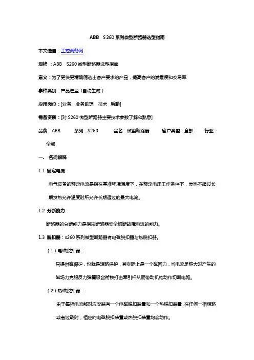
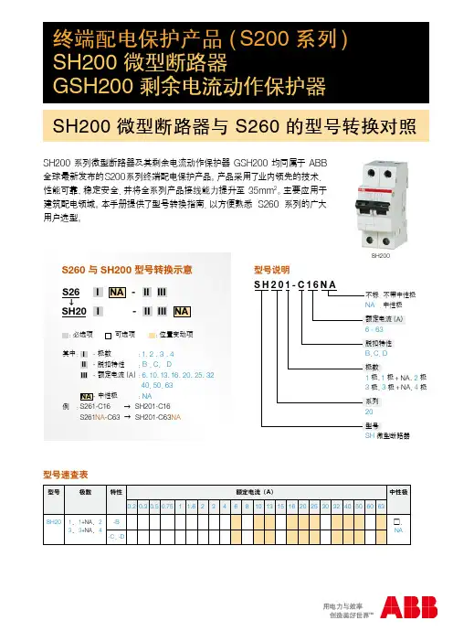
ABB S260微型断路器选型指南
- 格式:doc
- 大小:255.50 KB
- 文档页数:9
12351020307multiple of rated current123510203018multiple of rated currentKSpace foriden t i fi c a t ion markerTripping leverTrip in d i c a t orOperatorOperatingmechanismElectro-magnetic pro t ec t ionThermal protection-bimetal Upper terminalFixed contactMoving contactLower terminalDIN rail holderArc chamberUL 1077CSA C22.2 No. 235VDE 0641IEC-898Cable protectionBDelivery ClassA - Standard item, stock to 2 weeks lead timeB - Stock to 4 weeks lead timeC - 6 to 8 week lead timeD - 10 to 12 week lead timeE - Call for deliveryCUL 1077 CSA C22.2 - NO. 235VDE 0641 IEC-898Cable & equipment protectionS261-C1NA, 1P+NDelivery ClassA - Standard item, stock to 2 weeks lead timeB - Stock to 4 weeks lead timeC - 6 to 8 week lead timeD - 10 to 12 week lead timeE - Call for deliveryDUL 1077 CSA C22.2VDE 0641 IEC-898Cable & equipment protectionS263-D63, 3 poleDelivery ClassA - Standard item, stock to 2 weeks lead timeB - Stock to 4 weeks lead timeC - 6 to 8 week lead timeD - 10 to 12 week lead timeE - Call for deliveryK UL 1077CSA C22.2 - NO. 235VDE 0641IEC-898Cable & equipment protectionDelivery ClassA - Standard item, stock to 2 weeks lead timeB - Stock to 4 weeks lead timeC - 6 to 8 week lead timeD - 10 to 12 week lead timeE - Call for delivery1 KS is for standard U.S. size.UL 1077 CSA C22.2 - NO. 235VDE 0660Cable & equipment protectionDelivery ClassA - Standard item, stock to 2 weeks lead timeB - Stock to 4 weeks lead timeC - 6 to 8 week lead timeD - 10 to 12 week lead timeE - Call for deliveryUL 1077 CSA C22.2 - NO. 235VDE 0660Cable & equipment protection➀ For use with ring tongue or cable terminals only. Cannot be used with busbar system.2 No charge when ordered with the S280(W).Delivery ClassA - Standard item, stock to 2 weeks lead timeB - Stock to 4 weeks lead timeC - 6 to 8 week lead timeD - 10 to 12 week lead timeE - Call for deliveryUL 1077 VDE 0660CSA 22.2 No. 235Cable and Equip m ent Protection Direct current applicationsThe S280UC differs from standard miniature circuit breakers in that the UC versions include a permanent magnet which aids in the extinguishing of the arc during medium and high level faults. It is necessary toobserve the correct polarity and current direction when connecting the UC breakers. Two examples of correct connection are shown below.Termination points are marked on all UC type MCBs, points one (1) and four (4) are negative and points two(2) and three (3) are positive. Four pole breakers are also available for voltage reversal applications.Delivery ClassA - Standard item, stock to 2 weeks lead timeB - Stock to 4 weeks lead timeC - 6 to 8 week lead timeD - 10 to 12 week lead timeE - Call for deliveryLow Voltage Products & Systems14.13 Z UL 1077VDE 0660CSA 22.2No. 235Fast trip characteristicS281-Z16, 1 poleS282-Z32, 2 poleS283-Z32, 3 poleDiscount schedule CB7multiple of rated current multiple of rated current14.14 Low Voltage Products & SystemsVDE 0660Cable and equipment protectionDiscount schedule CB9480 VACDelivery ClassA - Standard item, stock to 2 weeks lead timeB - Stock to 4 weeks lead timeC - 6 to 8 week lead timeD - 10 to 12 week lead timeE - Call for deliveryLow Voltage Products & Systems 14.151PhaseDiscount schedule CB8For use on load side (bottom) of S260, S270, S280 and line side (top) of S280 MCBs.Insulated busbar assembly contains 2 separate circuits for use with 1, 1+N or 2 pole MCBs.For use on load side (bottom) of S260, S270, S280 and line side (top) of S280 MCBs.Insulated busbar assembly contains 3 separate circuits for use with 1 or 3 pole MCBs.For use on load side (bottom) of S260, S270, S280 and line side (top) of S280 MCBs.Delivery ClassA - Standard item, stock to 2 weeks lead timeB - Stock to 4 weeks lead timeC - 6 to 8 week lead timeD - 10 to 12 week lead timeE - Call for deliveryInsulated busbar assembly contains 4 separate circuits for use with 3+N1 or 4 pole MCBs.For use on load side (bottom) of S260, S270, S280 and line side (top) of S280 MCBs.14.16 Low Voltage Products & SystemsPhase with 1auxiliaryDiscount schedule CB8MCBs.(bottom) of S260, S270, S280 and line side (top) of S280 MCBs.Insulated busbar assembly contains 3 separate circuits for use with 1 or 3 pole MCBs. For use on load side (bottom) of S260, S270, S280 and line side (top) of S280 MCBs.(bottom) of S260, S270, S280 and line side (top) of S280 MCBs.Delivery ClassA - Standard item, stock to 2 weeks lead timeB - Stock to 4 weeks lead timeC - 6 to 8 week lead timeD - 10 to 12 week lead timeE - Call for deliveryLow Voltage Products & Systems 14.17PhaseMCB Busbar accessoriesDiscount schedule CB8For use on line side (top) of S260 and S270 MCBs.Insulated busbar assembly contains 4 separate circuits for use with 1+N or 2 pole MCBs.For use on load side (bottom) of S260, S270, S280 and line side (top) of S280 MCBs.Delivery ClassA - Standard item, stock to 2 weeks lead timeB - Stock to 4 weeks lead timeC - 6 to 8 week lead timeD - 10 to 12 week lead timeE - Call for deliveryInsulated busbar assembly contains 1 circuit for use with 1 pole MCBs.For use on line side (top) of S260 and S270 MCBs.NOTEALL BUSBARS MAY BE CENTER FED IN OR-DER TO DOUBLE THE AMPACITY RATING14.18 Low Voltage Products & SystemsFactory mountingAll accessories can be easily mounted in the fi eld. For factory mounting of any accessory devices, add $30 list to total price per breaker. To create complete catalog number, take suf fi x of accessory device following “S2-” and add suf fi x to end of breaker part number. Multiple suf fi xes must be added in alphabetical order.Example: S272-K20A1 $ 264 (2 pole, 20A breaker with type A1 shunt trip) S272-K20 @ $96 + A1@ $138 + factory mounting @ $30 = $264 S272-K20A2H11 $ 300 (2 pole, 20A breaker with type A2 shunt trip and H11 aux. contacts) S272-K20 @ $96 + A2 @ $138 + H11 @ $36 + factory mounting @ $30 = $300Auxiliary contacts and shunt trips may be mounted in combination.Discount schedule CB8NOTE: Above accesssories are for use with types S260, S270 and S280 breakers only.Delivery ClassA - Standard item, stock to 2 weeks lead timeB - Stock to 4 weeks lead timeC - 6 to 8 week lead timeD - 10 to 12 week lead timeE - Call for deliveryLow Voltage Products & Systems 14.19SA1SA2MB-3PDMB-CLS500-ME2Discount schedule CB8Delivery ClassA - Standard item, stock to 2 weeks lead timeB - Stock to 4 weeks lead timeC - 6 to 8 week lead timeD - 10 to 12 week lead timeE - Call for delivery14.20 Low Voltage Products & SystemsDiscount schedule CB8Low Voltage Products & Systems 14.21MountingUniversal mounting position using snap-on mounting to standard 35x7.5mm DIN rail.Miniature circuit breakers (MCBs) can also be mount e d to front of door using a panel cut-out with breaker handle pro t rud i ng through panel opening for external operation. Special front mount i ng kit type ME is avail a ble (see page 2.12).ConnectionTerminals are suitable for solid or fl exible conductors from 18 to 4 AWG (0.75 to 25mm 2) with no busbar connected. When max i m um busbar size of 36 mm 2 is used, maximum cable is 6 AWG (16 mm 2).Maximum tightening torque of 17.5 in-lb (2 Nm) for line/load terminals and 4.5 in-lb (0.5Nm) for ac c es s o r y device terminals.OperationMCBs are switched on by moving the handle to the upper po s i t ion. Stamped onto the handle switch, a “I” is visible con fi rming that the breaker is closed.The MCBs are “trip-free,” if the handle is being forced to the “ON” position, the breaker will still trip under fault conditions.The “O” marking indicates that the breaker is in the “OFF” position. The MCB is now open and the load is disconnected from line power.When a breaker has tripped, the MCB handle should fi rst be set to the full “OFF” position to make certain the trip mechanism has been reset. Once the fault has been determined and cleared the MCB can again be switched “ON”.MaintenanceABB miniature circuit breakers require no specialmaintenance; only normal electrical system maintenance pro c e d ures are required.Possible mounting arrangements of MCB accessoriesAuxiliary switch/bell alarmneutral disconnect Shunt trip and/or undervoltage releaseShunt trip or undervoltage release mounted with auxiliary switch14.22 Low Voltage Products & SystemsLower terminals can be bussed together with single phase or multi-phase busbars as shown. Upper ter m i n als can also be busbar con n ect e d.Dual function terminals provided in open position for connection to busbars. Pressing on screw head opens box terminal for cable insertion. Only the lower terminal is dual func t ion.Terminals allow for con n ec t ion of cable 18-4AWG. Conductors of different sizes may also be used in same terminal.Up to fi ve conductors, 16 AWG each, can be safely connected per terminal.Lower terminal can also be bussed with solidround con d uc t or.Cables can be connected to box terminals inaddition to busbar con n ec t ions on lower, dual function terminals.Thermal tripping is independent of frequency.1 Available for purchase. See page 14.19.Infl uence of frequency on electro-magnetic tripsMagnetic trip values shown on trip curves are valid for 50/60Hz ap p li c a t ions. For frequencies other than 50/60Hz, the mag n et i c (in s tan t a n eous) trip values are increased by the factor given below:16 2/3 - 60Hz100Hz 200Hz 400Hz DC Approx. factor 1 1.1 1.2 1.5 1.5Thermal tripping is independent of frequency.S260-BS280-KS270-KLet-through values I 2tFor other curves, please contact ABB Control.Version I 2t I PeakS260B TD9980 — S260C TD9981 — S260D TD9982 —S270K TD9972 TD9950 S280K TD9978 — S280Z TD9979 — S290C TD9985 —Version Amps Time-current tripS260B 6- 63 TD9725 S270K 0.5- 8 TD9705 10- 40 TD9706 50- 63 TD9707 S280K 0.2- 8 TD9708 10- 40 TD9709 50- 63 TD9710 S280Z 0.5- 63 TD9711DescriptionAll ABB miniature circuit breakers substantially reduce the maximum let-through current from the peak avail a ble short circuit current.I K - RMS current of fault I D - Max let-through of MCB V n - System voltage V B - Arc voltage of MCB t k - Breaking time of MCBType B, C, D Type K, ZCurrent carrying capacity of type “B”, “C”, “D”, “K” and “Z” thermal trip characteristics as a function of ambient tem p er a t ure.Terminal markingsInput optional from top or bottom.Miniature circuit breaker resistance valuesAmpacities for AWG wire are based on copper cable rated 75° C, except for 16AWG which is based on 60° C wire. Taken from UL508 Table 52.2.Consult applicable standards for futher detail and information. Comparison of IEC and AWG wire sizesS280S260 & S270 S290MB-CLFront mounting clipMB-3PDRHS2-MHandle mechanismAccessories12644126461265012652Many older styles of ABB miniature circuit breakers have been replaced by new and improved versions. Many of these newer styles can be directly interchanged, both electrically and physically, with the older version. There are also many international styles of ABB circuit breakers which are not normal stock items and may be inter-changed with stocked ABB versions.Note: MCB types S260/270 and S280 can be raised to the same height as older style S210 series MCBs through the use of a height adjuster (SZ-ES68/83; $ 30 list per 20). The height adjustor snaps onto the DIN rail and raises the height of com p o n ents 68mm to match that of the S210 series (83mm).S281U-K1S281UX-K1 S282UX-K10S283UX-K2014S281UX-K25LISTED10,00010001001010.10.01Current in multiples of breaker ampere rating1.02345681014.520301.0 1.35T i m e i n s e c o n d sTime –Current trip curveThermal release threshold:1.0-1.35X Magnetic release threshold:8-14.5X Ambient calibration temperature:25°CApproval UL489 UL File No. E212323 CE Marked Voltage240 VAC 1, 2, and 3 poleCurrent ratings (A) 0.2, 0.3, 0.5, 0.75, 1, 1.6, 2, 3, 4, 5, 6, 8,10, 13, 15, 16, 20, 25, 30, 32, 40, 50, 60, 63Interrupting capacity (A) 0.2 - 25A: 14kA @ 240VAC, 1, 2, and 3 pole 30 - 63A: 10kA @ 240VAC, 1, 2, and 3 pole Frequency 50/60 HzTerminals Dual function, up to (2) stripped wires plus fork style crimp terminals.Ring tongue terminal compatible Terminal range (1) 18 - 4 AWG or (2) 18 - 8 AWG (copper wire only) or (1) 18 - 4 AWG + (1) 18 - 14 AWGSolid or stranded wire, or mixedTerminal torque 18 lb.in., combination fl at blade /No. 2 posi-drive screw Service life 20,000 operations at rated loadHACR rating Heating, Air-Conditioning, and Refrigerationrating (marked on front of breaker)Ambient temperature 25° CThermal release (A) 1.0 - 1.35 x MCB amperage rating Magnetic release8 - 14.5 x MCB amperage ratingOperational temperature -25° to +55° C rangeScale 1:1141.0526.72.1053.43.1580.12.5464.51.77451.9950.5DINRAIL3.00763.54900.6917.5S281U-K_S281UX-K_S282UX-K_S283UX-K_UL 1077 CSA C22.2VDE 0641 IEC 947-2UL 1077 CSA C22.2VDE 0641 IEC 947-2Delivery ClassA - Standard item, stock to 2 weeks lead timeB - Stock to 4 weeks lead timeC - 6 to 8 week lead timeD - 10 to 12 week lead timeE - Call for deliveryUL 1077 CSA C22.2VDE 0641 IEC 947-1S502-D13Delivery ClassA - Standard item, stock to 2 weeks lead timeB - Stock to 4 weeks lead timeC - 6 to 8 week lead timeD - 10 to 12 week lead timeE - Call for deliveryUL 1077 CSA C22.2VDE 0641 IEC-898UL 1077 CSA C22.2VDE 0660Delivery ClassA - Standard item, stock to 2 weeks lead timeB - Stock to 4 weeks lead timeC - 6 to 8 week lead timeD - 10 to 12 week lead timeE - Call for deliveryS502UC-K0.15UL 1077 CSA C22.2VDE 0660Factory mount only Delivery ClassA - Standard item, stock to 2 weeks lead timeB - Stock to 4 weeks lead timeC - 6 to 8 week lead timeD - 10 to 12 week lead timeE - Call for deliveryBusbarsS500-RD3 Handle mechanism S5001 For use on 3p/3w systems, add jumper between 4 and 8N for operation of test button.Delivery ClassA - Standard item, stock to 2 weeks lead timeB - Stock to 4 weeks lead timeC - 6 to 8 week lead timeD - 10 to 12 week lead timeE - Call for deliveryApproximate dimensionsWiring diagram。

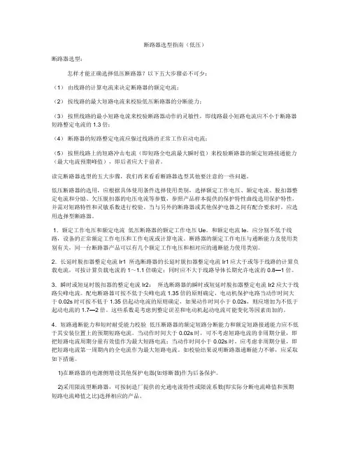
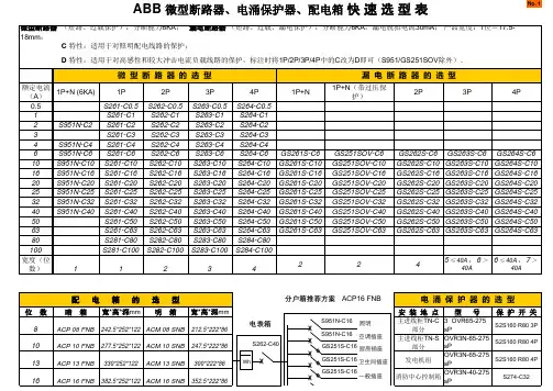
断路器选型指南(低压)断路器选型:怎样才能正确选择低压断路器?以下五大步骤必不可少:(1)由线路的计算电流来决定断路器的额定电流;(2)按线路的最大短路电流来校验低压断路器的分断能力;(3)按照线路的最小短路电流来校验断路器动作的灵敏性,即线路最小短路电流应不小于断路器短路整定电流的1.3倍;(4)断路器的短路整定电流应躲过线路的正常工作启动电流;(5)按照线路上的短路冲击电流(即短路全电流最大瞬时值)来校验断路器的额定短路接通能力(最大电流预期峰值),即后者应大于前者。
读完断路器选型的五大步骤,我们再来看看断路器选型其他要注意的一些问题。
低压断路器的选用,应根据具体使用条件选择使用类别,选择额定工作电压、额定电流、脱扣器整定电流和分励、欠压脱扣器的电压电流等参数,参照产品样本提供的保护特性曲线选用保护特性,并需对短路特性和灵敏系数进行校验。
当与另外的断路器或其他保护电器之间有配合要求时,应选用选择型断路器。
1.额定工作电压和额定电流低压断路器的额定工作电压Ue。
和额定电流Ie。
应分别不低于线路,设备的正常额定工作电压和工作电流或计算电流。
断路器的额定工作电压与通断能力及使用类别有关,同一台断路器产品可以有几个额定工作电压和相对应的通断能力使用类别。
2.长延时脱扣器整定电流Ir1 所选断路器的长延时脱扣器整定电流Ir1应大于或等于线路的计算负载电流,可按计算负载电流的1~1.1倍确定;同时应不大于线路导体长期允许电流的0.8—1倍。
3.瞬时或短延时脱扣器的整定电流Ir2:所选断路器的瞬时或短延时脱扣器整定电流Ir2应大于线路尖峰电流。
配电断路器可按不低于尖峰电流1.35倍的原则确定,电动机保护电路当动作时间大于0.02s时可按不低于1.35倍起动电流的原则确定,如果动作时间小于0.02s,则应增加为不低于起动电流的1.7—2倍。
这些系数是考虑到整定误差和电动机起动电流可能变化等因素而加的。
4.短路通断能力和短时耐受能力校验低压断路器的额定短路分断能力和额定短路接通能力应不低于其安装位置上的预期短路电流。

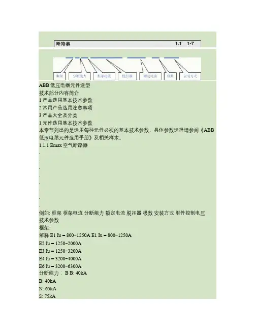
ABB低压电器元件选型技术部分内容简介1产品选用基本技术参数2常用产品选用注意事项3产品大全及分类1元件选用基本技术参数本章节列出的是选用每种元件必须的基本技术参数,具体参数选择请参阅《ABB 低压电器元件选用手册》及相关样本。
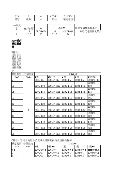
1.1.1 Emax空气断路器∙∙∙∙∙∙∙∙例如: 框架框架电流分断能力额定电流脱扣器极数安装方式附件控制电压技术参数框架:解释 E1 Iu = 800~1250A E1 Iu = 800~1250AE2 Iu = 1250~2000AE3 Iu = 1250~3200AE4 Iu = 3200~4000AE6 Iu = 3200~6300A分断能力: B B: 40kAB: 40kAN: 65kAS: 75kAH: 100kAV: 150KAL: 130KA框架电流: 12 1250A(E1,1250A--E6,6300A)脱扣器: PR111/P-LI PR111/P-LI PR111脱扣器,二段保护PR111/P-LI PR111脱扣器,二段保护PR111/P-LSI PR111脱扣器,三段保护PR111/P-LSIG PR111脱扣器,四段保护PR112/P-LSI PR112脱扣器,三段保护PR112/P-LSIG PR112脱扣器,四段保护PR112/PD-LSI PR112脱扣器,三段保护带对话单元PR112/PD-LSIG PR112脱扣器,四段保护带对话单元PR113/P-LSIG PR113脱扣器,四段保护PR113/PD-LSIG PR113脱扣器,四段保护带对话单元额定电流: R1250 1250A(E1,250A--E6,6300A)极数: 3P 3极(3或4极可选)安装方式: WHR W:抽出式(W:抽出式F:固定式)HR:水平后接线HR 水平后接线VR 垂直后接线F 延伸接线FL 端面接线(固定式无)附件控制电压:需要注明控制电压附件---YO,YC,YU,M 代号 E1Isomax塑壳断路器∙∙∙∙框架框架电流额定电流分断能力 1.1.2∙∙∙∙例如:脱扣器(TM热敏电磁脱扣器型无须提供)极数安装方式附件控制电压 TM热敏电磁脱扣器型:技术参数框架: 代号 S2 解释 S2S1 I=125S2 I=160S3 I=160,250S5 I=400,630S6 I=630,800分断能力: S SS1: B / N KA数值请查样本S2: B / N / S KA数值请查样本S3: N / H / L KA数值请查样本S5: N / H / L * KA数值请查样本S6: N / S / H / L KA数值请查样本框架电流: 160A 参阅框架额定电流: R125 125AS1-125, 10A----S6-800, 800A极数: 3P 3极(3或4极可选)安装方式: FFC F: 固定式F: 固定式P: 插入式(S6/S7不适用)W: 抽出式(S1/S2不适用)FC: 铜电缆前接线 F: 前接线EF: 加长前接线ES: 加长扩展前接线 FC: 铜电缆前接线 R: 螺纹后接线RC: 铜/铝后接线附件控制电压:需要注明控制电压附件---YO,YC,YU,M微处理器脱扣器型:技术参数框架:解释 S4 I=160,250S4 I=160,250S5 I=400,630S6 I=630,800S7 I=1250,1600S8 I=2000, 2500, 3200分断能力: N NS4: N / H / L KA数值请查样本S5: N / H / L KA数值请查样本S6: N / S / H / L KA数值请查样本S7: S / H / L KA数值请查样本S8: H / V(新品)KA数值请查样本框架电流: 250 参阅框架额定电流: R125 125AS4-160, 100A----S6-800, 3200A脱扣器: LSIG LSIG: 长延迟+短延迟+瞬动+接地故障I: 短路瞬动LI: 长延迟+瞬动LSI: 长延迟+短延迟+瞬动LSIG: 长延迟+短延迟+瞬动+接地故障LRIU: 长延迟+堵转+瞬动+断相或相不平衡( PR010/K,PR212/D,PR212/T 参见样本 )极数: 3P 3极(3或4极可选)安装方式: FFC F: 固定式F: 固定式P: 插入式(S6/S7不适用)W: 抽出式(S1/S2不适用)FC: 铜电缆前接线F: 前接线EF: 加长前接线ES: 加长扩展前接线FC: 铜电缆前接线R: 螺纹后接线RC: 铜/铝后接线附件控制电压:需要注明控制电压附件---YO,YC,YU,M代号 S4Isomax限流型塑壳断路器∙∙∙∙∙∙框架框架电流额定电流分断能力极数安装方式附件控制电压 1.1.3 例如: 技术参数框架: 代号解释 S3S3S2 I=1~100 分档S3 I=125,200S4 I=250S6 I=400,630XS2X分断能力70KA; S3X,S4X,S6X分断能力200KA参阅框架80AS2X-80: 1~80(19档), 3P,单磁 (参见样本) S2X-100:1~100(16档), 3P, 参见样本 S3X-125: 32,50,80,100,125S3X-200: 125,160,200S4X-250: 100,160,250S6X-400: 320,400S6X-630: 6303极(3或4极可选)F: 固定式F: 固定式P: 插入式(S6)W: 抽出式(S1/S2不适用)EF: 加长前接线F: 前接线EF: 加长前接线分断能力: X 框架电流:额定电流: 125 R80 极数:安装方式: 3P FEFES: 加长扩展前接线FC: 铜电缆前接线R: 螺纹后接线RC: 铜/铝后接线附件控制电压:需要注明控制电压附件---YO,YC,YU,M一体化剩余电流断路器∙∙∙∙∙∙∙例如:1.1.4 框架框架电流额定电流极数安装方式排列附件控制电压技术参数代号解释框架、分断能力、框架电流: S2N-160只有两种S2N-160,S3N-250额定电流: R80 80AS2-160: 12.5,16,20,25,32,40,50,63,80,100,125,160S3-250: 32,40,50,63,80,100,125,160,200,250S3及以下磁脱扣固定为10倍,非标可有5倍或单磁.极数: 4P 4P安装方式: FFC F: 固定式F: 固定式FC: 铜电缆前接线F: 前接线(S3N)FC: 铜电缆前接线(S2N)排列: V V:垂直安装V:垂直安装,H:水平安装附件控制电压:需要注明控制电压附件---YO,YC,YU,M电源自动切换装置DPT1.1.5∙切换回路数∙额定电流例如:技术参数切换回路数:额定电流:代号解释 SE SE双电源切换,TE三电源切换 1600 1600A主回路电流Isomax低压塑壳断路器配合剩余电流保护继电器 RC212 1.1.6∙框架电流∙安装方式例如:技术参数额定电流:安装方式:代号 2(代码)垂直安装解释配S2-160/4P: 选 2 配S2-160/4P: 选 2 配S3-250/4P: 选 3 垂直安装与断路器叠装: 垂直安装与断路器并装: 水平安装RCD∙剩余动作电流例如:技术参数代号剩余动作电流: 0.03解释 30 mA剩余动作电流:0.03 - 0.1 - 0.3 -0.4 - 1A剩余电流保护继电器RCQ1.1.7∙互感器内径例如:RCQ技术参数互感器内径:代号 110mm解释Φ110 mmΦ60 mm互感器内径Φ110 mm互感器内径接触器系列接触器1.2.11.2.1a∙主回路电流∙控制电压(交、直流)∙极数∙辅助触头数量例如:技术参数主回路电流: 极数:代号 30 30 10辅助触头数量控制电压(交、直流) ac220V解释 30A 3常开前一位代表常开,后一位代表常闭,数字为数量一常开前一位代表常开,后一位代表常闭,数字为数量交流220VTA热过载继电器 1.2.1b∙热脱扣电流∙轻重载(450以上)例如:技术参数主回路电流: 轻重载:代号450 DU解释 450A DU普通 DU普通 SU重载中间继电器 1.2.1c∙触点数、主触点组合方式(常开、常闭)∙控制电压、交、直流操作例如:技术参数代号触点数、主触点组合方式: 63 控制电压、交、直流操作:解释6常开,3常闭前一位代表常开,后一位代表常闭,数字为数量控制电压ac220VESB接触器1.2.1d∙额定电流∙主触点组合方式(常开、常闭)∙控制电压、交、直流操作∙灯具应用请参阅样本例如:技术参数额定电流:代号 63触点数、主触点组合方式: 31控制电压、交、直流操作:灯具应用:控制电压ac220V请参阅样本解释 63A 20 对AC1/AC7a负载 24 对AC1/AC7a负载 40 对AC1/AC7a负载 63 对AC1/AC7a负载 6常开,3常闭ESB20: 可选: 20, 02, 11ESB24: 可选: 40, 04, 22, 31, 13 ESB40: 可选: 40 ESB63: 可选: 40前一位代表常开,后一位代表常闭,数字为数量电动机起动器 1.2.2∙框架电流和分断能力∙热脱扣电流例如:技术参数框架电流和分断能力:代号 325额定电流 20解释MS325 50KA,0.1-25A MS325 50KA,0.1-25A MS450 50kA,16~50A MS451 50KA,16~50A MS495 50KA,40~100A MS496 100KA,40~100A MS497100KA,16~100A 20APSS、PST、PSTB软启动器∙电机额定电流(结合功率考虑)∙负载类型(重、轻载)∙控制电源电压例如:1.2.3技术参数代号电机额定电流: 18/30 负载类型(重、轻载):参阅样本控制电源电压:参阅样本解释18A外接法/30A内接法(PSS)开关熔断器组 OS、OESA∙额定电流∙极数例如:1.3.1技术参数额定工作电流:极数:代号 250 3P 解释 250A 3极负荷开关/隔离开关 OT、OETL ∙额定电流∙极数例如:1.3.2技术参数额定工作电流:极数:代号 250 3P解释 250A 3极Easyline熔断丝切换隔离开关XLP三极∙额定电流例如:1.3.3技术参数额定电流:代号 00解释 160A按照样本根据电流选择型号微型断路器 1.4.1∙额定电流∙极数(最后位数字为可选项,1为1极,2为2极…依此类推,例如S261)∙分断能力∙脱扣特性(B、C、D、K等)例如:技术参数极数:代号261脱扣特性: C额定电流:20解释 1极最后位数字为可选项,1为1极,2为2极…依此类推 CB、C、D、K、Z根据样本,由不同系列不同电流而不同 20A根据样本,由不同系列有不同电流范围过电流保护电磁式剩余电流动作断路器 DS250S∙∙∙∙∙例如:1.4.2额定电流极数(最后位数字为可选项,1为1极,2为2极…依此类推,例如DS252) 分断能力脱扣特性(B、C)剩余电流动作电流技术参数极数:代号DS253解释 3极脱扣特性: C 40 0.03额定电流:剩余电流动作电流:最后位数字为可选项,2为2极…依此类推(无1极) CB、C两种 40A根据样本,由不同系列有不同电流范围 30mADS9∙额定电流∙极数(最后位数字为可选项,1为1极,2为2极。

包括标准附件:
分励(YO) 220V
合闸线圈(YC) 220V
电机(M) 220V
机械及电气跳闸指示
辅助接点: 10CO - PR121
4CO - PR122
注: 1.以上开关均可选择3极,4极;标注为3P ,4P 。
2.以上开关均可选固定式或抽出式。
3。
脱扣器 PR121/P 为基本保护型脱扣器,四段保护(默认配置);
PR122/P 为可拓展保护型脱扣器,四段保护(部分电量采集) PR122/PD 为可带通讯功能的拓展保护型脱扣器
PR123/P 为可拓展保护型脱扣器,四段保护(全电量采集) PR123/PD 为可带通讯功能的拓展保护型脱扣器
L ,S ,I ,G 分别为过载,短路短延时,短路瞬时,接地保护。
例:E3S25 R2500 PR121/P 3p ABB Emax 空气断路器选型表
+ABB--ACB--E。