UART的异步串口通信VHDL实现
- 格式:pdf
- 大小:52.20 KB
- 文档页数:4
基于FPGA的UART电路设计与仿真基于FPGA的UART电路设计与仿真Design and Simulation of UART Circuit Based on FPGA(蚌埠中国⼈民解放军汽车管理学院) 杨⼤柱Yang, Dazhu摘要:⽂章介绍了⼀种采基于FPGA 实现UART电路的⽅法,并对系统结构进⾏了模块化分解以适应⾃顶向下的设计⽅法。
采⽤有限状态机对接收器模块和发送器模块进⾏了设计,所有功能的实现全部采⽤VHDL进⾏描述,并在Modelsim环境下进⾏了仿真,结果表明了该设计的正确性和可靠性。
关键词:UART;FPGA;RS-232;有限状态机中图分类号:TP332 ⽂献标识码:AAbstract:This paper introduces a method to design UART circuit based on FPGA. and the system structure is divided into modularization to fit the design method of Top-Down.The receiver and transfer are designed by FSM (Finite State Machine).All functions are described by VHDL.We stimulate the functions under Modelsim environment,the result proves the validity and reliability of the design.Keywords:UART;FPGA;RS-232;FSMUART(通⽤异步收发器)是⼴泛使⽤的串⾏数据传输协议。
UART允许在串⾏链路上进⾏全双⼯的通信。
专⽤的UART集成电路如8250,8251,NS16450等已经相当复杂,有些含有许多辅助的模块(如FIF0),在实际应⽤中,往往只需要⽤到UART的⼏个基本功能,使⽤专⽤芯⽚会造成资源浪费和成本提⾼,我们可以将所需要的UART功能集成到FPGA内部,从⽽简化了整个系统电路,提⾼了可靠性、稳定性和灵活性。
通用异步收发器(Universal Asynchronous Receiver Transmitter,UART)是数字通信领域流行和广泛使用的一种接口设备,主要用来控制符合RS 232-C协议的计算机与串行设备间的通信。
普通串行外设和计算机间的通信,一般使用通用的串行接口芯片,但是这种接口芯片存在体积较大、接口复杂以及成本较高的缺点,会使得硬件设计更加复杂,并且结构与功能相对固定,无法根据设计的需要对其逻辑控制进行灵活的修改。
而目前日趋成熟的SOC技术则要求将整个设计的功能集成在单片或几块芯片当中,因此,将UART的功能集成在FPGA芯片当中,可以使整个系统更为灵活、紧凑,性能也更加稳定。
本文提出了一种使用VHDL语言开发UAWT的方法,实现了FPGA与计算机之间的数据通信,并将其应用于FPGA芯片开发的功能验证当中,从而衍生出了将UART嵌入到EPGA芯片,与计算机互联的一种直观的FPGA设计的验证和调试方法。
1 UART通信原理UART采用通用的RS 232-C串行接口标准,该协议的优点是使用广泛,几乎所有计算机和串行外设当中都置有这种接口,其传输距离可达15 m,并且实现较简单,用于双向连接时最少只需要2条导线即可实现基本通信。
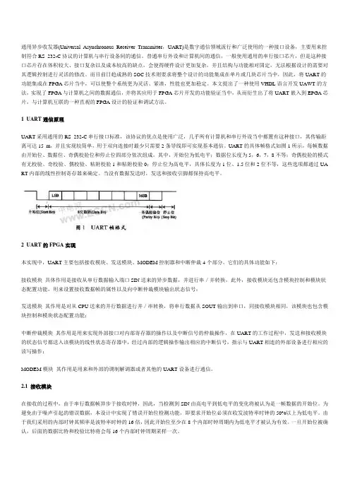
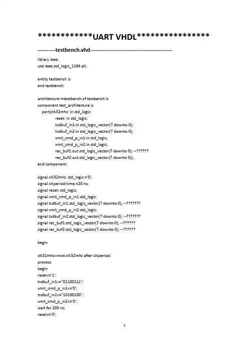
UART的具体帧格式如图1所示,每帧数据由开始位、数据位、奇偶校验位和停止位四部分依次组成。
其中,开始位为低电平;数据位长度为5,6,7,8不等;奇偶校验的模式有无校验、奇校验、偶校验、粘附校验1和粘附校验0;停止位为高电平,具体长度为1位、1.5位和2位不等,这些选项都通过UA RT内部的线性控制寄存器来确定。
当没有数据发送时,发送和接收引脚都保持高电平。
2 UART的FPGA实现本实现中,UART主要包括接收模块、发送模块、MODEM控制器和中断仲裁4个部分。
它们的具体功能如下:接收模块具体作用是接收从串行数据输入端口SIN送来的异步数据,并进行串/并转换,此外,接收模块还包含模块控制和模块状态配置功能,用来设置接收数据帧的属性以及向中断仲裁模块输出状态信号;发送模块其作用是对从CPU送来的并行数据进行并/串转换,将串行数据从SOUT输出到串口,同接收模块相同,该模块也包含模块控制和模块状态配置功能;中断仲裁模块其作用是用来实现外部接口对内部寄存器的操作以及中断信号的仲裁操作,在UART的工作过程中,发送和接收模块的状态信号都送入该模块的线性状态寄存器中,经过内部的逻辑操作输出相应的中断信号,指示与UART相连的外部设备进行相应的读写操作;MODEM模块其作用是用来和外部的调制解调器或者其他的UART设备进行通信。
单片机UART通信实现在单片机系统中,UART(通用异步收发器)通信是一种常见的串口通信方式。
通过UART通信,可以实现单片机与外部设备之间的数据传输。
本篇文章将介绍如何使用单片机实现UART通信,并提供相应的代码示例。
一、UART通信原理UART通信是一种串行通信方式,其中数据按照位的形式依次传输。
UART接口包括发送端和接收端,发送端将要传输的数据通过串行方式发送出去,接收端将接收到的数据按位恢复为原始数据。
通信的核心是波特率,即数据传输的速度。
发送端和接收端必须以相同的波特率进行通信,以确保数据的正确传输。
二、单片机UART通信的硬件连接实现单片机UART通信的关键是正确连接相应的硬件。
典型的单片机UART通信硬件连接如下:发送端:- 单片机的TX(发送)引脚连接到外部设备的RX(接收)引脚- 单片机的GND引脚连接到外部设备的GND引脚接收端:- 单片机的RX(接收)引脚连接到外部设备的TX(发送)引脚- 单片机的GND引脚连接到外部设备的GND引脚三、单片机UART通信的软件实现在软件方面,需要编写相应的代码来配置单片机的UART通信模块。
以下是一个示例代码,用于实现基本的UART通信功能。
```c#include <reg51.h>#define BAUDRATE 9600 // 波特率设置为9600bpsvoid uart_init(){TMOD = 0x20; // 设置定时器1为8位自动重装模式TH1 = -(256 - (11059200 / 12 / 32) / BAUDRATE); // 设置波特率TL1 = TH1; // 初始化定时器1的初值TR1 = 1; // 启动定时器1SCON = 0x50; // 标识为8位UART模式EA = 1; // 允许全局中断ES = 1; // 允许串口中断}void uart_send(unsigned char dat)SBUF = dat; // 将数据写入发送寄存器 while (!TI); // 等待发送完毕TI = 0; // 清除发送完成标志}unsigned char uart_receive(){while (!RI); // 等待接收完毕RI = 0; // 清除接收标志return SBUF; // 返回接收到的数据}void main(){unsigned char data;uart_init(); // 初始化UART通信模块 while (1)data = uart_receive(); // 接收数据uart_send(data); // 发送接收到的数据}}```以上代码是基于8051系列单片机的实现示例,具体的单片机型号和编程语言可能有所不同,但基本原理是相同的。
用vhdl语言在cpld上实现串行通信一、概述串行通信是现代通信领域中最为常见的一种通信方式。
通过串行通信,现代社会中的各种设备可以以最高效的方式进行数据传输,实现快速、准确的信息交换。
而vhdl语言则是数字电路设计领域中最为常用的一种描述语言,因为vhdl 语言可以描述数字电路的不同行为,对于数字电路的模拟和仿真非常方便。
在本文中,我们将介绍如何使用vhdl语言在cpld 上实现串行通信。
二、串行通信的基本原理串行通信是指在数据传输过程中,数据位是按照顺序一个一个相继传输的。
串行通信的传输速率相对较慢,但是传输距离远,主要是通过数据信号占用两个或者三个核心线来完成的。
串行通信的数据信号一般由三个部分构成:开始位、数据位和停止位。
开始位一般用于启动数据传输,而停止位则用于结束数据传输。
三、vhdl语言概述VHDL(VHSIC Hardware Description Language)是美国国防工业联合会(VHSIC)在80年代末期为了解决数字电路设计中的复杂性而开发的一种硬件描述语言,是一种基于文本的语言。
VHDL语言主要用来描述数字逻辑和数字电路。
VHDL语言本身就是一种结构化的、层次化的语言,可以很好地体现出数字电路的层次关系。
四、使用vhdl语言在cpld上实现串行通信的步骤1、确定串行通信的传输速率和数据格式。
在确定串行通信的传输速率和数据格式之前,需要确定串行通信的基本参数,包括其传输速率、在接收端进行判定数据是否有效的时间程度、以及在发送端和接收端之间互相传输数据的位数。
这些参数对于后续的设计极为重要。
2、编写串行通信的vhdl模块。
在vhdl模块中,需要包括发送和接收两个部分,分别对应于硬件接口中的发送和接收部分。
发送部分主要是将数据按照规定的格式进行串行传输,而接收部分则主要是将串行传输的数据再转换为并行数据。
3、完成vhdl模块的仿真测试。
在完成vhdl模块的设计之后,需要进行仿真测试,以验证vhdl模块的正确性和稳定性。
VHDL设计举例:一个简单的UART-------------------------------------------------------------------- Copyright (c) 1992,1993,1994, Exemplar Logic Inc. All rights reserved.---------------------------------------------------------------------- This design implements a UART.------ V ersion : Original Creation-- V ersion : Modified to std_logic types-- V ersion : Extended reset to be more effective.-- Introduced OTHERS clause.------------------------------------------------------------------LIBRARY ieee;use _logic_;use _logic_;use _logic_;ENTITY uart ISPORT (clkx16 : IN std_logic;-- Input clock. 16x bit clockread : IN std_logic;-- Received data read strobewrite : IN std_logic;-- Transmit data write stroberx : IN std_logic;-- Receive data linereset : IN std_logic;-- clear dependenciestx : OUT std_logic;-- Transmit data linerxrdy : OUT std_logic;-- Received data ready to be readtxrdy : OUT std_logic;-- Transmitter ready for next byte parityerr : OUT std_logic;-- Receiver parity errorframingerr : OUT std_logic;-- Receiver framing erroroverrun : OUT std_logic;-- Receiver overrun errordata : INOUT std_logic_vector(0 TO 7)); -- Bidirectional data bus END uart;ARCHITECTURE exemplar OF uart IS-- Transmit data holding registerSIGNAL txhold : std_logic_vector(0 TO 7);-- Transmit shift register bitsSIGNAL txreg : std_logic_vector(0 TO 7);SIGNAL txtag2 : std_logic;-- tag bits for detectingSIGNAL txtag1 : std_logic;-- empty shift regSIGNAL txparity : std_logic;-- Parity generation register-- Transmit clock and control signalsSIGNAL txclk : std_logic; -- Transmit clock: 1/16th of clkx16SIGNAL txdone : std_logic;-- …1‟ when shifting of byte is doneSIGNAL paritycycle : std_logic;-- …1‟ on next to last shift cycleSIGNAL txdatardy : std_logic; -- …1‟ when data is ready in txhold-- Receive shift register bitsSIGNAL rxhold : std_logic_vector(0 TO 7);-- Holds received data for readSIGNAL rxreg : std_logic_vector(0 TO 7);-- Receive data shift registerSIGNAL rxparity : std_logic;-- Parity bit of received dataSIGNAL paritygen : std_logic;-- Generated parity of received dataSIGNAL rxstop : std_logic;-- Stop bit of received data-- Receive clock and control signalsSIGNAL rxclk : std_logic;-- Receive data shift clockSIGNAL rxidle : std_logic; -- …1‟ when receiver is idling SIGNAL rxdatardy : std_logic; -- …1‟ when data is ready to be readBEGINmake_txclk:PROCESS (reset, clkx16)V ARIABLE cnt : std_logic_vector(2 DOWNTO 0);BEGIN-- Toggle txclk every 8 counts, which divides the clock by 16IF reset=…1‟ THENtxclk …0‟) ;ELSIF clkx16‟event AND clkx16=…1‟ THENIF (cnt = “000”) THENtxclk …0‟) ;rx1 := …0‟ ;rxclk …0‟) ;txtag1 …0‟) ;rxparity …1‟);rxparity …0‟) ;parityerr …Z‟) ;-- Latch data bus during writetxhold <= data WHEN write = …1‟ ELSE txhold;-- Receive data ready output signalrxrdy <= rxdatardy;-- Transmitter ready for write when no data is in txholdtxrdy <= NOT txdatardy;-- Run-time simulation check for transmit overrunASSERT write = …0‟ OR txdatardy = …0‟REPORT “Transmitter overrun error” SEVERITY WARNING; END exemplar;。
UART 16倍频采样的VHDL实现随着电子设计自动化(EDA)技术的发展,可编程逻辑器件FPGA/CPLD已经在许多方面得到了广泛应用,而UART(通用异步收发器)是在数字通信和控制系统中广泛使用的串行数据传输协议。
因此越来越多用户根据自己的需要,以EDA技术作为开发手段,用一块FPGA/CPLD 设计出符合自己需要的UART芯片。
基于FPGA/ CPLD的UART设计在诸多文献中都有论述,在此不再对UART整个功能模块实现做太多的论述。
本文着重分析UART接收器起始位的检测。
3倍频采样的缺陷首先,串行异步通信规定了字符数据的传送格式。
每一帧数据由起始位、数据位、奇偶校验位、停止位和线路空闲状态组成,格式如图1所示。
一般情况起始位为1位,数据位为5、6、7或8位、奇偶校验位为1位,停止位为1、1.5或2位。
其中的起始位和停止位就是用来实现字符的同步。
在空闲状态,传送线为逻辑“1”状态。
数据的传送总是以一个“起始位”开始的,接着是要传送的若干数据位,低位先行,最后是一个“1”状态的“停止位”;那么,当接收器检测到一个“1”向“0”的跳变时,便视为可能的起始位。
起始位被确认后,就知道发送器已开始发送,当接收了已协议好的位数后并接收到字符帧中停止位就是一帧字符数据已发送完毕。
这样,接收器就知道发送器何时开始发送数据和何时结束发送数据。
要提高接收器的接收准确性,减少误码率,必须要用比数据波特率高n 倍(n≥1)的速率对数据进行采样。
文献2中采用了非常规的3倍频采样方法:用3倍频的波特率对每一位数据进行采样(如图2所示),然后对3次采样结果进行判决。
如果3次采样中至少有2次为高电平,则接收这一位数据被判决为高电平,否则,为低电平。
此方法刚开始给人感觉比常规的16倍频采样准确性高,因为每一位数据都进行3取2的判决,而16倍频采样对每位数据只进行一次中间采样。
然而笔者在实际应用中发现了其存在抗干扰性差,移植性差等不足。
异步FIFO的VHDL设计下面是一个异步FIFO的VHDL设计示例:```vhdllibrary ieee;use ieee.std_logic_1164.all;entity AsyncFIFO isgenericDATA_WIDTH : natural := 8; -- 数据宽度FIFO_DEPTH : natural := 16 -- FIFO深度portclk : in std_logic; -- 时钟信号rst : in std_logic; -- 复位信号read_en : in std_logic; -- 读使能write_en : in std_logic; -- 写使能read_data : out std_logic_vector(DATA_WIDTH-1 downto 0); -- 读数据write_data : in std_logic_vector(DATA_WIDTH-1 downto 0); -- 写数据full : out std_logic; -- FIFO满标志empty : out std_logic -- FIFO空标志end AsyncFIFO;architecture Behavioral of AsyncFIFO istype buffer_array is array (FIFO_DEPTH-1 downto 0) ofstd_logic_vector(DATA_WIDTH-1 downto 0);signal buffer : buffer_array; -- 数据缓冲区signal wr_ptr : natural range 0 to FIFO_DEPTH-1; -- 写指针signal rd_ptr : natural range 0 to FIFO_DEPTH-1; -- 读指针signal count : natural range 0 to FIFO_DEPTH-1; -- 缓冲区中数据个数beginprocess (clk)beginif rising_edge(clk) thenif rst = '1' thenwr_ptr <= 0;rd_ptr <= 0;count <= 0;elseif write_en = '1' and full = '0' then -- 写使能且FIFO非满buffer(wr_ptr) <= write_data;wr_ptr <= wr_ptr + 1;count <= count + 1;end if;if read_en = '1' and empty = '0' then -- 读使能且FIFO非空read_data <= buffer(rd_ptr);rd_ptr <= rd_ptr + 1;count <= count - 1;end if;end if;end if;end process;full <= '1' when count = FIFO_DEPTH-1 else '0';empty <= '1' when count = 0 else '0';end Behavioral;```在上面的代码中,`DATA_WIDTH`和`FIFO_DEPTH`是异步FIFO的泛型参数,可以根据实际需求进行配置。
基于VerilogHDL的UART设计季雄段吉海胡媛媛袁柯于海生(桂林电子工业学院 通信与信息工程系,广西 桂林 541004)摘要:UART是广泛使用的串行数据通信电路,因其要求的传输线少,可靠性高,传输距离远,所以系统间互联常采用RS—232接口方式,一般说来,该接口由硬件(UART专用芯片)实现。
文章基于VerilogHDL语言,结合有限状态机的设计方法来实现UART,将其核心功能集成到FPGA上,使整体设计紧凑、小巧,实现的UART功能稳定、可靠,为RS—232接口提供了一种新的解决方案;同时,与其他设计方法相比较,利用有限状态机的方法具有结构模式直观简单,设计流程短,程序层次分明,易综合,可靠性高等优点,必将在EDA技术中发挥重要作用。
关键词:VerilogHDL; UART;帧格式;状态机引言随着微机系统的广泛运用和微机网络的极大发展,UART(Universal Asynchronous Receive Transmitter)【1】在数据通信及控制系统中得到了广泛运用。
8250、NS16450等芯片都是常见的UART 器件[2],这类芯片已经相当复杂,有的含有许多辅助模块(如FIFO),但在实际中有时只需要使用UART的部分功能,因而会造成一定的资源浪费。
FPGA在现代电子设计中的广泛运用,使我们可以充分利用其资源,在芯片上集成UART的功能模块,这样就无需外接专用UART芯片,从而简化了电路,缩小了体积,设计的灵活性更大。
文章通过分析UART的功能,利用有限状态机[4]来描述UART核心控制逻辑的方法,将其核心功能集成,从而使整个设计更加稳定、可靠。
基本的UART通信只需要两条信号线就可以完成数据的相互通信。
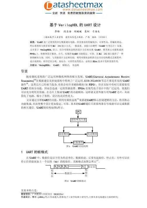
UART的结构如图1所示。
图1 UART的结构图1 UART的帧格式在UART中,数据位是以字符为传送单位,数据的前、后要有起始位、停止位,另外可以在停止位的前面加上一个比特(bit)的校验位。
************UART VHDL**************** ----------testbench.vhd----------------------------------------------library ieee;use ieee.std_logic_1164.all;entity testbench isend testbench;architecture mtestbench of testbench iscomponent test_architecture isport(clk32mhz: in std_logic;reset: in std_logic;txdbuf_in1:in std_logic_vector(7 downto 0);txdbuf_in2:in std_logic_vector(7 downto 0);xmit_cmd_p_in1:in std_logic;xmit_cmd_p_in2:in std_logic;rec_buf1:out std_logic_vector(7 downto 0); --??????rec_buf2:out std_logic_vector(7 downto 0));end component;signal clk32mhz: std_logic:='0';signal clkperiod:time:=20 ns;signal reset: std_logic;signal xmit_cmd_p_in1:std_logic;signal txdbuf_in1:std_logic_vector(7 downto 0); --???????signal xmit_cmd_p_in2:std_logic;signal txdbuf_in2:std_logic_vector(7 downto 0); --???????signal rec_buf1:std_logic_vector(7 downto 0); --??????signal rec_buf2:std_logic_vector(7 downto 0); --??????beginclk32mhz<=not clk32mhz after clkperiod;processbeginreset<='1';txdbuf_in1<="01100111";xmit_cmd_p_in1<='0';txdbuf_in2<="10100100";xmit_cmd_p_in2<='0';wait for 200 ns;reset<='0';wait for 100 ns;xmit_cmd_p_in1<='1';xmit_cmd_p_in2<='1';wait for 200000 ns;xmit_cmd_p_in1<='0';xmit_cmd_p_in2<='0';wait;end process;uut_test_architecture: test_architecture port map (clk32mhz=>clk32mhz, reset=>reset, txdbuf_in1=>txdbuf_in1,txdbuf_in2=>txdbuf_in2, xmit_cmd_p_in1=>xmit_cmd_p_in1, xmit_cmd_p_in2=>xmit_cmd_p_in2,rec_buf1=>rec_buf1,rec_buf2=>rec_buf2);end mtestbench;--------------------------------test_architecture.vhd----------------------------------library ieee;use ieee.std_logic_1164.all;entity test_architecture isport(clk32mhz: in std_logic;reset: in std_logic;txdbuf_in1:in std_logic_vector(7 downto 0);txdbuf_in2:in std_logic_vector(7 downto 0);xmit_cmd_p_in1:in std_logic;xmit_cmd_p_in2:in std_logic;rec_buf1:out std_logic_vector(7 downto 0); --??????rec_buf2:out std_logic_vector(7 downto 0));end test_architecture;architecture mtest_architecture of test_architecture iscomponent uart_module isPort (clk32mhz,reset,rxd,xmit_cmd_p_in:in std_logic;rec_ready,txd_out,txd_done_out:out std_logic;txdbuf_in:in std_logic_vector(7 downto 0); --???????rec_buf:out std_logic_vector(7 downto 0)); --??????end component;signal rec_ready1,txd_out1,txd_done_out1:std_logic;signal rec_ready2,txd_out2,txd_done_out2:std_logic;beginuart_module_0: uart_moduleport map(clk32mhz=>clk32mhz,reset=>reset,xmit_cmd_p_in=>xmit_cmd_p_in1, rec_ready=>rec_ready1,txd_out=>txd_out1,txd_done_out=>txd_done_out1,txdbuf_in=>txdbuf_in1, rxd=>txd_out2,rec_buf=>rec_buf1);uart_module_1: uart_moduleport map(clk32mhz=>clk32mhz,reset=>reset, xmit_cmd_p_in=>xmit_cmd_p_in2, rec_ready=>rec_ready2,txd_out=>txd_out2,txd_done_out=>txd_done_out2,txdbuf_in=>txdbuf_in2,rxd=>txd_out1,rec_buf=>rec_buf2);end mtest_architecture;------------------------------- uart_module.vhd-----------------------------------------library IEEE;use IEEE.STD_LOGIC_1164.ALL;use IEEE.STD_LOGIC_ARITH.ALL;use IEEE.STD_LOGIC_UNSIGNED.ALL;entity uart_module isPort (clk32mhz,reset,rxd,xmit_cmd_p_in:in std_logic;rec_ready,txd_out,txd_done_out:out std_logic;txdbuf_in:in std_logic_vector(7 downto 0); --???????rec_buf:out std_logic_vector(7 downto 0)); --??????end uart_module;architecture Behavioral of uart_module iscomponent recieverPort (bclkr,resetr,rxdr:in std_logic;r_ready:out std_logic;rbuf:out std_logic_vector(7 downto 0));end component;component transferPort (bclkt,resett,xmit_cmd_p:in std_logic;txdbuf:in std_logic_vector(7 downto 0);txd:out std_logic;txd_done:out std_logic);end component;component baudPort (clk,resetb:in std_logic;bclk:out std_logic);end component;signal b:std_logic;beginu1:baud port map(clk=>clk32mhz,resetb=>reset,bclk=>b); --????u2:receiverport map(bclkr=>b,resetr=>reset,rxdr=>rxd,r_ready=>rec_ready,rbuf=>rec_buf);u3:transferport map(bclkt=>b,resett=>reset,xmit_cmd_p=>xmit_cmd_p_in,txdbuf=>txdbuf_in, txd=>txd_out,txd_done=>txd_done_out);end Behavioral;----------------------------- baud.vhd------------------------------------------------------------library IEEE;use IEEE.STD_LOGIC_1164.ALL;use IEEE.STD_LOGIC_ARITH.ALL;use IEEE.STD_LOGIC_UNSIGNED.ALL;entity baud isPort (clk,resetb:in std_logic;bclk:out std_logic);end baud;architecture Behavioral of baud isbeginprocess(clk,resetb)variable cnt:integer;beginif resetb='1' then cnt:=0; bclk<='0'; --??elsif rising_edge(clk) thenif cnt>=208 then cnt:=0; bclk<='1'; --??????else cnt:=cnt+1; bclk<='0';end if;end if;end process;end Behavioral;----------------------------------transfer.vhd------------------------------------------- library IEEE;use IEEE.STD_LOGIC_1164.ALL;use IEEE.STD_LOGIC_ARITH.ALL;use IEEE.STD_LOGIC_UNSIGNED.ALL;entity transfer isgeneric(framlent:integer:=8);Port (bclkt,resett,xmit_cmd_p:in std_logic; --????????txdbuf:in std_logic_vector(7 downto 0):="11001010";txd:out std_logic;txd_done:out std_logic);end transfer;architecture Behavioral of transfer istype states is (x_idle,x_start,x_wait,x_shift,x_stop); --??????signal state:states:=x_idle;signal tcnt:integer:=0;-----the following signals are in the main process;signal xcnt16:std_logic_vector(4 downto 0):="00000"; --??????signal xbitcnt:integer:=0;signal txds:std_logic;beginprocess(bclkt,resett,xmit_cmd_p,txdbuf) --?????????beginif resett='1' then state<=x_idle; txd_done<='0'; txds<='1'; --??elsif rising_edge(bclkt) thencase state iswhen x_idle=> --??1??????????if xmit_cmd_p='1' then state<=x_start; txd_done<='0';else state<=x_idle; end if;when x_start=> --??2?????????--if xcnt16>="01111" then state<=x_wait; xcnt16<="00000";if xcnt16>="01110" then state<=x_wait; xcnt16<="00000";else xcnt16<=xcnt16+1; txds<='0'; state<=x_start;end if;when x_wait=> --??3?????if xcnt16>="01111" thenif xbitcnt=framlent then state<=x_stop;xbitcnt<=0;xcnt16<="00000";else state<=x_shift; end if;else xcnt16<=xcnt16+1; state<=x_wait; end if;when x_shift=>txds<=txdbuf(xbitcnt); xbitcnt<=xbitcnt+1; state<=x_wait;--??4????????????when x_stop=> --??5????????if xcnt16>="01111" thenif xmit_cmd_p='0' then state<=x_idle; xcnt16<="00000";else xcnt16<=xcnt16; state<=x_stop; end if;txd_done<='1';else xcnt16<=xcnt16+1; txds<='1'; state<=x_stop;end if;when others=>state<=x_idle;end case;end if;txd<=txds;end process;end Behavioral;--------------------reveiver.vhd----------------------------------------------------------library IEEE;use IEEE.STD_LOGIC_1164.ALL;use IEEE.STD_LOGIC_ARITH.ALL;use IEEE.STD_LOGIC_UNSIGNED.ALL;entity reciever isgeneric(framlenr:integer:=8);Port (bclkr,resetr,rxdr:in std_logic; --????????r_ready:out std_logic;rbuf:out std_logic_vector(7 downto 0));end reciever;architecture Behavioral of reciever istype states is (r_start,r_center,r_wait,r_sample,r_stop); --??????signal state:states:=r_start;signal rxd_sync:std_logic;----the folloing signals are in the "pro2" process.signal count:std_logic_vector(3 downto 0); --??????signal rcnt:integer:=0;signal rbufs:std_logic_vector(7 downto 0);beginpro1:process(rxdr)beginif rxdr='0' then rxd_sync<='0';else rxd_sync<='1';end if;end process;pro2:process(bclkr,resetr,rxd_sync) --?????????beginif resetr='1' then state<=r_start; count<="0000"; --??elsif rising_edge(bclkr) thencase state iswhen r_start=> --??1??????if rxd_sync='0' then state<=r_center; r_ready<='0'; rcnt<=0;else state<=r_start; r_ready<='0';end if;when r_center=> --??2????????if rxd_sync='0' thenif count="1111" then state<=r_wait; count<="0000";else count<=count+1; state<=r_center;end if;else state<=r_start;end if;when r_wait=>--??3?????if count>="1110" thenif rcnt=framlenr then state<=r_stop;count<="0000";rcnt<=0;else state<=r_sample; end if;else count<=count+1; state<=r_wait;end if;when r_sample=>rbufs(rcnt)<=rxd_sync; rcnt<=rcnt+1;state<=r_wait; --??4????????when r_stop=>r_ready<='1'; rbuf<=rbufs;state<=r_start; --??4??????????when others=>state<=r_start;end case;end if;end process;end Behavioral;Notice:综合前仿真和综合后仿真结果不一致:图1. 综合前仿真结果图2. 综合后仿真结果。
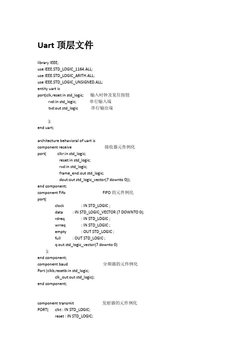
Uart顶层文件library IEEE;use IEEE.STD_LOGIC_1164.ALL;use IEEE.STD_LOGIC_ARITH.ALL;use IEEE.STD_LOGIC_UNSIGNED.ALL;entity uart isport(clk,reset:instd_logic;输入时钟及复位按钮rxd:instd_logic;串行输入端txd:outstd_logic串行输出端);end uart;architecture behavioral of uart iscomponent receive接收器元件例化port( clkr:instd_logic;reset:instd_logic;rxd:instd_logic;frame_end:outstd_logic;dout:outstd_logic_vector(7 downto 0));end component;component Fifo FIFO的元件例化port(clock : IN STD_LOGIC ;data : IN STD_LOGIC_VECTOR (7 DOWNTO 0);rdreq : IN STD_LOGIC ;wrreq : IN STD_LOGIC ;empty : OUT STD_LOGIC ;full : OUT STD_LOGIC ;q:out std_logic_vector(7 downto 0));end component;component baud分频器的元件例化Port (clkb,resetb:instd_logic;clk_out:outstd_logic);end component;component transmit发射器的元件例化PORT( clkt : IN STD_LOGIC;reset : IN STD_LOGIC;lock : IN STD_LOGIC;din : IN STD_LOGIC_VECTOR(7 downto 0);trans : OUT STD_LOGIC;trans_end : OUT STD_LOGIC );end component;component flag接受器工作状态原件的例化port(rxd,clk2 :in std_logic;REN:outstd_logic );end component;component counter移位寄存器的元件例化port(REN,clk2:in std_logic;w,t:outstd_logic );end component;signal frame_end,clk2,wrreq,full,empty,REN,w,t,j,k:std_logic;连接线信号的说明signal dout,data,buf,q,din:std_logic_vector(7 downto 0);signal rdreq,lock,trans,trans_end:std_logic;beginwrreq<=frame_end;data<=buf;din<=q;lock<=j;rdreq<=k;txd<=trans;receive1:receive port map(clk,reset,rxd,frame_end,dout) ;例化元件的引用baud1:baud port map(clk,reset,clk2);Fifo1:Fifo port map(clk2,data,rdreq,wrreq,empty,full,q);transmit1:transmit port map(clk,reset,lock,din,trans,trans_end);flag1:flag port map(rxd,clk2,REN);counter1:counter port map(REN,clk2,w,t );process(frame_end,dout)锁存器接收器的frame_end下,将接受器的输出寄存到beginbuf,收到wrreq信号时,写入fifoif(frame_end='1')thenbuf<=dout;end if;end process;process(REN)输出工作状态选择器begin REN=0,处于接受状态,令fifo的读操作rdreq及发射器的锁if REN='1' then存lock为0j<=w; REN=1,接收counter提供信号w,t分别给rdreq和lockk<=t;elsek<='0';j<='0';end if;end process;end behavioral;uart编译结果Uart功能仿真结果uart时序仿真结果Uart接收器library IEEE;use IEEE.STD_LOGIC_1164.ALL;use IEEE.STD_LOGIC_ARITH.ALL;use IEEE.STD_LOGIC_UNSIGNED.ALL;entity receive isPort (clkr:instd_logic; 时钟输入reset:instd_logic; 复位端rxd:instd_logic; 串行输入frame_end:outstd_logic;工作状态输出dout:outstd_logic_vector(7 downto 0));并行输出end receive;architecture behavioral of receive isbeginpro:process(clkr,reset,rxd)variable number:std_logic_vector(3 downto 0);variable count:std_logic_vector(3 downto 0);variable buf:std_logic_vector(7 downto 0);beginif reset='1' thennumber:="0000";count:="0000";frame_end<='1';elsifrising_edge(clkr) thenif number="0000"then 判断是否接受到起始位,在clk下连续8个时钟接受为0if rxd='0' then 0则认为接受到起始位,开始接受数据if count<"1000"thencount:=count+1;elsedout<="00000000";count:="0000";number:=number+1;frame_end<='0';end if;end if;elsif number>="0001" and number<="1000"then 接受数据位if count<"1111"then每16个clk时钟接受一位数据位count:=count+1;elsecount:="0000";number:=number+1;frame_end<='0';buf(7 downto 1) := buf(6 downto 0) ;buf(0):=rxd;end if;elsif number = "1001" then接受结束位,到此一帧数据,即十位,接受完毕if count<"1111"then并开始将八位数据输出count:=count+1;elsecount:="0000";dout<= buf ;buf:="00000000";number:="0000";frame_end<='1';end if;elsecount:="0000";number:="0000";buf:="00000000";frame_end<='1';end if;end if;end process;endbehavioral;uart接收器功能仿真结果Uart接收器时序仿真结果Uart接收器编译结果由quartus功能提供的FIFOQuartus下megawizard工具提供的FIFO设置一路时钟输入,wrreq和rdreq分别控制写入和读出操作提供empty,full工作状态输出Data{7~0}输入并行数据Q{7~0}输出并行数据深度和宽度为8-- megafunction wizard: %FIFO%-- GENERATION: STANDARD-- VERSION: WM1.0-- MODULE: scfifo-- ============================================================-- File Name: Fifo.vhd-- Megafunction Name(s):-- scfifo---- Simulation Library Files(s):-- altera_mf-- ============================================================-- ************************************************************-- THIS IS A WIZARD-GENERATED FILE. DO NOT EDIT THIS FILE!---- 9.0 Build 235 06/17/2009 SP 2 SJ Web Edition-- ************************************************************--Copyright (C) 1991-2009 Altera Corporation--Your use of Altera Corporation's design tools, logic functions--and other software and tools, and its AMPP partner logic--functions, and any output files from any of the foregoing--(including device programming or simulation files), and any--associated documentation or information are expressly subject --to the terms and conditions of the Altera Program License--Subscription Agreement, Altera MegaCore Function License--Agreement, or other applicable license agreement, including, --without limitation, that your use is for the sole purpose of--programming logic devices manufactured by Altera and sold by --Altera or its authorized distributors. Please refer to the--applicable agreement for further details.LIBRARY ieee;USE ieee.std_logic_1164.all;LIBRARY altera_mf;USE altera_mf.all;ENTITY Fifo ISPORT(clock : IN STD_LOGIC ;data : IN STD_LOGIC_VECTOR (7 DOWNTO 0);rdreq : IN STD_LOGIC ;wrreq : IN STD_LOGIC ;empty : OUT STD_LOGIC ;full : OUT STD_LOGIC ;q : OUT STD_LOGIC_VECTOR (7 DOWNTO 0) );END Fifo;ARCHITECTURE SYN OF fifo ISSIGNAL sub_wire0 : STD_LOGIC ;SIGNAL sub_wire1 : STD_LOGIC_VECTOR (7 DOWNTO 0);SIGNAL sub_wire2 : STD_LOGIC ;COMPONENT scfifoGENERIC (add_ram_output_register : STRING;intended_device_family : STRING;lpm_numwords : NATURAL;lpm_showahead : STRING;lpm_type : STRING;lpm_width : NATURAL;lpm_widthu : NATURAL;overflow_checking : STRING;underflow_checking : STRING;use_eab : STRING);PORT (rdreq : IN STD_LOGIC ;empty : OUT STD_LOGIC ;clock : IN STD_LOGIC ;q : OUT STD_LOGIC_VECTOR (7 DOWNTO 0);wrreq : IN STD_LOGIC ;data : IN STD_LOGIC_VECTOR (7 DOWNTO 0);full : OUT STD_LOGIC);END COMPONENT;BEGINempty <= sub_wire0;q <= sub_wire1(7 DOWNTO 0);full <= sub_wire2;scfifo_component : scfifoGENERIC MAP (add_ram_output_register => "OFF",intended_device_family => "Stratix II",lpm_numwords => 8,lpm_showahead => "OFF",lpm_type => "scfifo",lpm_width => 8,lpm_widthu => 3,overflow_checking => "ON",underflow_checking => "ON",use_eab => "ON")PORT MAP (rdreq =>rdreq,clock => clock,wrreq =>wrreq,data => data,empty => sub_wire0,q => sub_wire1,full => sub_wire2);END SYN;-- ============================================================ -- CNX file retrieval info-- ============================================================ -- Retrieval info: PRIVATE: AlmostEmpty NUMERIC "0"-- Retrieval info: PRIVATE: AlmostEmptyThr NUMERIC "-1"-- Retrieval info: PRIVATE: AlmostFull NUMERIC "0"-- Retrieval info: PRIVATE: AlmostFullThr NUMERIC "-1"-- Retrieval info: PRIVATE: CLOCKS_ARE_SYNCHRONIZED NUMERIC "0"-- Retrieval info: PRIVATE: Clock NUMERIC "0"-- Retrieval info: PRIVATE: Depth NUMERIC "8"-- Retrieval info: PRIVATE: Empty NUMERIC "1"-- Retrieval info: PRIVATE: Full NUMERIC "1"-- Retrieval info: PRIVATE: INTENDED_DEVICE_FAMILY STRING "Stratix II"-- Retrieval info: PRIVATE: LE_BasedFIFO NUMERIC "0"-- Retrieval info: PRIVATE: LegacyRREQ NUMERIC "1"-- Retrieval info: PRIVATE: MAX_DEPTH_BY_9 NUMERIC "0"-- Retrieval info: PRIVATE: OVERFLOW_CHECKING NUMERIC "0"-- Retrieval info: PRIVATE: Optimize NUMERIC "2"-- Retrieval info: PRIVATE: RAM_BLOCK_TYPE NUMERIC "0"-- Retrieval info: PRIVATE: SYNTH_WRAPPER_GEN_POSTFIX STRING "0"-- Retrieval info: PRIVATE: UNDERFLOW_CHECKING NUMERIC "0"-- Retrieval info: PRIVATE: UsedW NUMERIC "0"-- Retrieval info: PRIVATE: Width NUMERIC "8"-- Retrieval info: PRIVATE: dc_aclr NUMERIC "0"-- Retrieval info: PRIVATE: diff_widths NUMERIC "0"-- Retrieval info: PRIVATE: msb_usedw NUMERIC "0"-- Retrieval info: PRIVATE: output_width NUMERIC "8"-- Retrieval info: PRIVATE: rsEmpty NUMERIC "1"-- Retrieval info: PRIVATE: rsFull NUMERIC "0"-- Retrieval info: PRIVATE: rsUsedW NUMERIC "0"-- Retrieval info: PRIVATE: sc_aclr NUMERIC "0"-- Retrieval info: PRIVATE: sc_sclr NUMERIC "0"-- Retrieval info: PRIVATE: wsEmpty NUMERIC "0"-- Retrieval info: PRIVATE: wsFull NUMERIC "1"-- Retrieval info: PRIVATE: wsUsedW NUMERIC "0"-- Retrieval info: CONSTANT: ADD_RAM_OUTPUT_REGISTER STRING "OFF" -- Retrieval info: CONSTANT: INTENDED_DEVICE_FAMILY STRING "Stratix II" -- Retrieval info: CONSTANT: LPM_NUMWORDS NUMERIC "8"-- Retrieval info: CONSTANT: LPM_SHOWAHEAD STRING "OFF"-- Retrieval info: CONSTANT: LPM_TYPE STRING "scfifo"-- Retrieval info: CONSTANT: LPM_WIDTH NUMERIC "8"-- Retrieval info: CONSTANT: LPM_WIDTHU NUMERIC "3"-- Retrieval info: CONSTANT: OVERFLOW_CHECKING STRING "ON"-- Retrieval info: CONSTANT: UNDERFLOW_CHECKING STRING "ON"-- Retrieval info: CONSTANT: USE_EAB STRING "ON"-- Retrieval info: USED_PORT: clock 0 0 0 0 INPUT NODEFVAL clock-- Retrieval info: USED_PORT: data 0 0 8 0 INPUT NODEFVAL data[7..0]-- Retrieval info: USED_PORT: empty 0 0 0 0 OUTPUT NODEFVAL empty-- Retrieval info: USED_PORT: full 0 0 0 0 OUTPUT NODEFVAL full-- Retrieval info: USED_PORT: q 0 0 8 0 OUTPUT NODEFVAL q[7..0]-- Retrieval info: USED_PORT: rdreq 0 0 0 0 INPUT NODEFVAL rdreq-- Retrieval info: USED_PORT: wrreq 0 0 0 0 INPUT NODEFVAL wrreq-- Retrieval info: CONNECT: @data 0 0 8 0 data 0 0 8 0-- Retrieval info: CONNECT: q 0 0 8 0 @q 0 0 8 0-- Retrieval info: CONNECT: @wrreq 0 0 0 0 wrreq 0 0 0 0-- Retrieval info: CONNECT: @rdreq 0 0 0 0 rdreq 0 0 0 0-- Retrieval info: CONNECT: @clock 0 0 0 0 clock 0 0 0 0-- Retrieval info: CONNECT: full 0 0 0 0 @full 0 0 0 0-- Retrieval info: CONNECT: empty 0 0 0 0 @empty 0 0 0 0-- Retrieval info: LIBRARY: altera_mfaltera_mf.altera_mf_components.all -- Retrieval info: GEN_FILE: TYPE_NORMAL Fifo.vhd TRUE-- Retrieval info: GEN_FILE: TYPE_NORMAL Fifo.inc FALSE-- Retrieval info: GEN_FILE: TYPE_NORMAL Fifo.cmp TRUE-- Retrieval info: GEN_FILE: TYPE_NORMAL Fifo.bsf FALSE-- Retrieval info: GEN_FILE: TYPE_NORMAL Fifo_inst.vhd FALSE-- Retrieval info: GEN_FILE: TYPE_NORMAL Fifo_waveforms.html TRUE-- Retrieval info: GEN_FILE: TYPE_NORMAL Fifo_wave*.jpg FALSE-- Retrieval info: LIB_FILE: altera_mfFIFO的编译结果FIFO的功能仿真结果FIFO的时序仿真结果uart发射器LIBRARY ieee;USE ieee.std_logic_1164.all;use IEEE.STD_LOGIC_ARITH.ALL;use IEEE.STD_LOGIC_UNSIGNED.ALL;ENTITY transmit ISPORT(clkt : IN STD_LOGIC; 时钟输入reset : IN STD_LOGIC; 复位lock : IN STD_LOGIC; 锁存din : IN STD_LOGIC_VECTOR(7 downto 0);并行输入trans : OUT STD_LOGIC; 串行输出trans_end : OUT STD_LOGIC );输出状态END transmit;ARCHITECTURE behavioral OF transmit ISBEGINpro:process(clkt,reset,lock)variable number:STD_LOGIC_VECTOR(3 downto 0);variable count:STD_LOGIC_VECTOR(3 downto 0);variable buf:STD_LOGIC_VECTOR(7 downto 0);beginif reset='1' then 复位操作number:="0000";trans_end<='1';trans<='1';count:="0000";elsifrising_edge(clkt)thenif (lock='1') and (number<"1101") thenif number="0000" then 接受并行数据并锁存if count<"1111" thencount:=count+1;elsecount:="0000";trans_end<='0';trans<='1';number:=number+1;buf:=din;end if;elsif number = "0001" then输出起始位if count<"1111"thencount:=count+1;elsecount:="0000";trans_end<='0';trans<='0';number:=number+1;end if;elsif number>="0010" and number<="1001"then输出数据位if count<"1111"thencount:=count+1;elsecount:="0000";number:=number+1;trans_end<='0';trans <= buf(7) ;buf := buf(6 downto 0)&'0';end if;elsif number = "1010" then 输出结束位if count<"1111"thencount:=count+1;elsecount:="0000";trans_end<='0';trans<= '1' ;number:=number+1;end if;elsif number = "1011" thenif count<"1111"thencount:=count+1;elsecount:="0000";trans_end<='1';trans<= '1' ;number:=number+1;end if;end if;elsif lock='0' thencount:="0000";trans_end<='1';trans<='1';number:="0000";end if;end if;end process;end behavioral;uart发射器编译结果发射器的功能仿真发射器的时序仿真其他辅助模块分频器:为FIFO提供输入时钟信号library IEEE;use IEEE.STD_LOGIC_1164.ALL;use IEEE.STD_LOGIC_ARITH.ALL;use IEEE.STD_LOGIC_UNSIGNED.ALL;entity baud isPort (clkb,resetb:instd_logic; 输入时钟及复位clk_out:outstd_logic);输出1/16CLKb时钟end baud;architecture Behavioral of baud isbeginprocess(clkb,resetb)variable div:integer range 0 to 16;beginif resetb='1' thendiv:=0; clk_out<='0';elsifclkb 'event and clkb='1' thendiv:=div+1;if div=8 thenclk_out<='0';elsif div=16 thenclk_out<='1';div:=0;end if;end if;end process;end Behavioral;FLAG 判断输入rxd状态,确定rxd接收结束时提供REN信号使能发射器library IEEE;use IEEE.STD_LOGIC_1164.ALL;use IEEE.STD_LOGIC_ARITH.ALL;use IEEE.STD_LOGIC_UNSIGNED.ALL;entity flag isport(rxd,clk2 :in std_logic;REN:outstd_logic );end flag;architecture flag of flag isbeginprocess(rxd,clk2)variable number:std_logic_vector(3 downto 0);beginif rising_edge(clk2)thenif rxd='1' thenif number<"1010"thennumber:=number+1;连续10个时钟内接收到rxd为1则判定输入状态已结束else REN<='1';令REN=1后发射器开始工作end if;else number:="0000";REN<='0';end if;end if;end process;end flag;计数器:发射器开始工作后为fifo读操作和transmit锁存操作提供工作状态控制输入library IEEE;use IEEE.STD_LOGIC_1164.ALL;use IEEE.STD_LOGIC_ARITH.ALL;use IEEE.STD_LOGIC_UNSIGNED.ALL;entity counter isport(REN,clk2:in std_logic;由REN使能后在clk2时钟下工作w,t:outstd_logic );end counter;architecture counter of counter isbeginprocess(REN,clk2)variable p:std_logic_vector(11 downto 0):="011111111111";variable o:std_logic_vector(11 downto 0):="100000000000";beginif REN='1'thenif rising_edge(clk2)thenp:=p(10 downto 0)&P(11);o:=o(10 downto 0)&o(11);end if;end if;w<=p(11); w为发射器lock接入t<=o(11); t为fifo内rdreq接入end process;end counter;RTL仿真原理图Fifo:接收器RECEIVE:发送器TRANSMIT:UART:。
本科生毕业论文(设计) 题目:UART电路的VHDL设计及实现院系计算机学院专业通信工程指导教师韩晓茹学生姓名姚芳学号0040622062004 年6 月9日UART电路的VHDL设计及实现作者:姚芳指导教师:韩晓茹摘要:UART是设备和设备间进行通信的关键,当一个设备需要和另一个连接的设备进行通信时,通常采用数字信号,这种源自并行的信号必须转换成串行信号才能通过有线或无线传输到另一台设备。
在接收端,串行信号又转换成并行信号进行处理,UART处理这种数据总线和串行口之间的串-并和并-串转换。
本文所要实现的就是就是这种串-并和并-串的转换,使之能够进行数据的传输。
本文介绍了用FPGA技术实现UART电路的一种方法,用VHDL进行编程,在Modelsim下进行编译及仿真等。
关键词:FPGA,VHDL,UART,接收,发送Abstract:UART is the key of communications between devices.When a device needs to communicate with a connected device,usually digital signals applied,which must be transformed into serialised signal to another device through wires or wireless space.When being received to process, the serialised signals must be transformed to parellised signals.UART processes this serial_data to parallel_data /parallel _data to serial_data transform between data bus and slave port. This paper is to implement this serial to parallel and parallel to serial transform and make the transferring between data properly.This paper introduces a method implemented by FPGA technique programmed by VHDL,simulated and compiled by Modelsim.Keyword:FPGA,VHDL ,UART,receive ,send目录第1章绪论 (1)1.1本文研究的意义 (1)1.2本文研究的内容 (1)第2章FPGA和VHDL语言简介 (2)2.1FPGA (2)2.2VHDL语言 (2)第3章串行通信的基本概念 (5)3.1串行通信的特点及通信方式 (5)3.2传输速率与传输距离 (11)3.3UART简介 (12)第4章UART结构 (13)4.1串行数据时钟 (13)4.2UART发送器 (14)4.3格式化 (14)4.4发送器状态 (14)4.5UART接收器 (15)4.6错误检测 (15)第5章UART的VHDL语言编写 (17)5.1UART的串行数据 (17)5.2UART整体结构 (18)5.3UART的接收部分 (19)5.4UART的发送部分 (21)5.5波特率发生部分 (23)5.6总线接口及中断 (25)第6章功能仿真 (26)6.1总体布线图 (26)6.2接收部分 (27)6.3发送部分 (30)第7章小结 (33)致谢: (34)参考文献: (35)第1章绪论1.1 本文研究的意义在1980至1990年代,提供FPGA数万逻辑门的FPGA器件主要被系统设计人员用作“连接逻辑”,将电路板上的不同元器件连接到一起,或用来修正ASIC不方便处理的问题。
基于FPGA的UART设计与实现
董秀洁;付凯
【期刊名称】《中原工学院学报》
【年(卷),期】2012(023)002
【摘要】提出了一种基于FPGA的UART的实现方法.利用有限状态机和硬件描述语言VHDL实现了通用异步收发器UART IP核的设计,给出了用VHDL实现UART 的数学模型,并进行了仿真分析.结果表明,各项通信指标均满足要求,并可提高系统的可靠性和稳定性.
【总页数】4页(P66-69)
【作者】董秀洁;付凯
【作者单位】中原工学院,郑州450007;中原工学院,郑州450007
【正文语种】中文
【中图分类】TN402
【相关文献】
1.基于FPGA的UART设计与实现 [J], 于志翔
2.基于FPGA的UART模块设计与实现 [J], 刘博
3.基于FPGA的UART设计与实现 [J], 刘宝军;王中训;娄阳;张珉;钟强
4.基于FPGA的UART抗干扰接收装置设计与实现 [J], 张名淑;张雅迪;王旭;陈飞;钱祥利
5.基于FPGA的UART串行通信参数自适应设计与实现 [J], 杨洋;和蕾;王旭;钱祥利;陈飞;李静
因版权原因,仅展示原文概要,查看原文内容请购买。
基于FPGA的UART设计与实现作者:何勇来源:《现代电子技术》2010年第11期摘要:介绍了应用现场可编程门阵列(FPGA)设计和实现通用异步收发器UART的方法。
采用有限状态机模型形式化描述了UART的功能,在此基础上用硬件描述语言VHDL编程实现了UART,并使用Quartus Ⅱ软件中的嵌入式逻辑分析仪SignalTapⅡ对数据传输进行了检测,验证了设计的正确性。
关键词:FPGA; UART; 有限状态机; SignalTapⅡ中图分类号:TP332 文献标识码:A文章编号:1004-373X(2010)11-0154-03Design and Realization of UART Based on FPGAHE Yong(College of Computer Science & Information, Guizhou University, Guiyang 550025, China)Abstract: A method to design and realize the universal asynchronous receiver/transmitter(UART) based on the field programmable gate array(FPGA) is introduced.The functions of UART are described formally by using the finite state machine model, by the way, UART is realized on the basis of VHDL. Moreover, the data transmission is detected with SignalTapⅡ which is an embedded logic analyzer in Quartus Ⅱ. The result proves the validity of the design.Keywords: FPGA; UART; finite state machine; SignalTapⅡ0 引言通用异步收发器(Universal Asynchronous Receiver/Transmitter,UART)可以和各种标准串行接口,如RS 232和RS 485等进行全双工异步通信,具有传输距离远、成本低、可靠性高等优点[1]。
科目:VHDL语言与数字系统EDA设计专业:微电子与固体电子学学生姓名:陈庆宇提交日期: 2011年5月26号目录实验一 (1)实验二 (5)实验三 (9)实验四 (11)实验五 (17)作业 (27)实验一1. 实验内容1. 用IF 语句设计一个四-十六译码器;2. 用CASE 语句设计一个四-十六译码器;3. 用GENERATE 语句构造一个串行的十六进制计数器。
2. 实验目的会用VHDL 语言实现一些简单的组合逻辑和时序逻辑,学会使用相关EDA 软件进行VHDL 代码的输入、仿真。
3. 实验方案本实验有三个小实验组成,先分别将方案分别列出:a :用IF 语句设计一个四-十六译码器接口信号的定义如图--1:g1,g2a ,g2b 为片选信号,sel 为输入 编码,y 为译码输出b :用CASE 语句设计一个四-十六译码器 接口定义同样的如图-1:g1,g2a ,g2b 为片选信号,sel 为输入编码,y 为译码输出c :用GENERATE 语句构造一个串行的十六进制计数器先用行为描述设计一个D 触发器,然后用结构描述的方法将四个D 触发器用特定的接法连接起来。
其中clk 、clr 为时钟和清零输入,q 为计数输出。
4.仿真结果(仿真软件:Quartus II 7.2 )a:用IF语句实现的四-十六译码器的仿真结果上图为:片选信号无效的时候的仿真波形,输出为高电平。
上图为:片选信号有效的时候的仿真波形。
b:用CASE语句实现的一个四-十六译码器的仿真结果(直接让片选有效)c:用GENERATE语句构造的串行的十六进制计数器的仿真波形注:当clr为0时对计数结果清零,时钟上升沿计数器加1.5.关键部分代码a:用IF语句设计一个四-十六译码器PROCESS(G1,g2a,g2b,sel)beginif(g1='1'and g2a='0'and g2b='0')thenif(sel="0000")then y<="1111111111111110";elsif(sel="0001")then y<="1111111111111101";elsif(sel="0010")then y<="1111111111111011";elsif(sel="0011")then y<="1111111111110111";elsif(sel="0100")then y<="1111111111101111";elsif(sel="0101")then y<="1111111111011111";elsif(sel="0110")then y<="1111111110111111";elsif(sel="0111")then y<="1111111101111111";elsif(sel="1000")then y<="1111111011111111";elsif(sel="1001")then y<="1111110111111111";elsif(sel="1010")then y<="1111101111111111";elsif(sel="1011")then y<="1111011111111111";elsif(sel="1100")then y<="1110111111111111";elsif(sel="1101")then y<="1101111111111111";elsif(sel="1110")then y<="1011111111111111";elsif(sel="1111")then y<="0111111111111111";else y<="XXXXXXXXXXXXXXXX";end if;else Y<="1111111111111111";end if;end process;b:用CASE语句设计一个四-十六译码器case sel iswhen "0000"=>y<="1111111111111110";when "0001"=>y<="1111111111111101";when "0010"=>y<="1111111111111011";when "0011"=>y<="1111111111110111";when "0100"=>y<="1111111111101111";when "0101"=>y<="1111111111011111";when "0110"=>y<="1111111110111111";when "0111"=>y<="1111111101111111";when "1000"=>y<="1111111011111111";when "1001"=>y<="1111110111111111";when "1010"=>y<="1111101111111111";when "1011"=>y<="1111011111111111";when "1100"=>y<="1110111111111111";when "1101"=>y<="1101111111111111";when "1110"=>y<="1011111111111111";when "1111"=>y<="0111111111111111";when others =>y<="XXXXXXXXXXXXXXXX";end case;c:用GENERATE语句构造一个串行的十六进制计数器architecture count16er of count16 iscomponent dfip isport(d:in std_logic;clr:in std_logic;ck:in std_logic;q:out std_logic;qb:out std_logic);end component;signal clk_in:std_logic_vector(4 downto 0);beginclk_in(0)<=clk;G1:for i in 0 to 3 generateU0:dfip port map(d=>clk_in(i+1),ck=>clk_in(i),clr=>clr,q=>q(i),qb=>clk_in(i+1));end generate;end count16er;实验二1. 实验内容1. 设计一个两位二进制的加法器2. 设计一个两位的BCD 计数器2. 实验目的会用VHDL 语言的多种描述方式实现典型的组合逻辑和时序逻辑,学会使用相关EDA 软件进行VHDL 代码的输入、仿真。
班级学号姓名同组人实验日期室温大气压成绩实验六通用异步串行口(UART)实验一、实验目的1、掌握异步串行通信协议;2、掌握2812异步收发器模块的应用。
二、实验设备1、一台装有CCS软件的计算机;2、DSP试验箱的TMS320F2812主控板;3、DSP硬件仿真器。
三、实验原理1、异步串行通信协议在传输数据前,数据线处于高电平状态,这称为表示态。
传输开始后,数据线由高电平转为低电平状态,这称为起始位;起始位后面接着5-8个信息位;信息为后面是校验位;校验位后是停止位“1”。
传输完毕后,可以立即开始下一个字符的传输;否则,数据线再次进入标识态。
上面提到的信息位的位数(5~8位)、停止位的位数(1位、1.5位或2位)、校验的方式(奇偶验、偶校验或不校验)等参数都可以根据不同需要进行设置,但对于同一个传输系统中的首发两端来说,这些参数必须保持一致。
异步串行通信方式中另一个重要的参数是波特率。
在一般的“0”“1”系统中,波特率就是每秒钟传输的位数。
国际上规定了一个标准波特率系列,他们是最常用的波特率。
标准波特率系列为110、300、600、1200、1800、2400、4800、9600和19200。
发送端和接收端必须设置统一的波特率,否则无法正确接收数据。
2、电平转换RS-232-C标准中规定-5V~-15V位逻辑“1”,+5V~+15V位逻辑“0”,因此要用专门的芯片完成TTL电平与RS-232电平的转换,如MAX3232。
3、串行口调试助手该计算机端程序可以监测计算机串口接收和发送数据的情况。
本实验中需要用该程序帮助观察实验结果。
四、实验步骤1、用串口线连接实验箱的 UART 模块与计算机串行口;2、在 CCS 环境中打开本实验的工程Example_sci.pjt,编译,生成输出文件,通过仿真器把执行代码下载到DSP 芯片;3、在计算机上运行串口调试助手程序,设置串口为Com1,波特率为9600,校验为None,停止位为1 位,十六进制显示,以待观察从DSP 往PC 串口发送的数据;4、选择“View”->“memory”,起始地址设为“0x1000”,“Page”项设置为“I/O”,以待观察寄存器的值;5、在串口调试助手程序的发送窗口键入任意字符(如“5A”)以待发送至DSP,并且选择手动发送模式(即不选中自动发送项)和十六进制发送;五、实验总结本实验为通用异步串行接口(UART)实验,运行程序后能通过在串口调试助手程序中,在接收窗口中可以观察正确接收到0X00~0XFF的数据。
UART串口通信的基本原理和通信过程UART(Universal Asynchronous Receiver/Transmitter)是一种常见的串口通信协议,用于在计算机和外部设备之间进行数据传输。
本文将详细解释UART串口通信的基本原理和通信过程,并提供一个全面、详细、完整且深入的解释。
1. UART串口通信的基本原理UART串口通信是一种基于异步传输的通信协议,它使用两根信号线(TX和RX)来实现数据的传输。
UART通信的基本原理如下:•数据位:UART通信中的每个字符由一定数量的数据位组成,通常为8位。
每个数据位可以表示一个字节(8位二进制数)。
•停止位:每个字符之后会有一个停止位,用于指示一个字符的结束。
通常情况下,UART通信中的停止位为1个。
•起始位:每个字符之前会有一个起始位,用于指示一个字符的开始。
通常情况下,UART通信中的起始位为1个。
•波特率:UART通信中的波特率(Baud Rate)表示每秒钟传输的比特数。
常见的波特率有9600、115200等。
UART通信使用的是异步传输,即发送端和接收端没有共同的时钟信号。
因此,在通信过程中,发送端和接收端需要事先约定好相同的波特率,以确保数据的正确传输。
2. UART串口通信的通信过程UART串口通信的通信过程包括数据的发送和接收两个步骤。
下面将详细介绍UART串口通信的通信过程。
数据发送过程1.发送端准备数据:发送端需要准备要发送的数据,并将数据存储在发送缓冲区中。
2.发送端发送起始位:发送端在发送数据之前,会先发送一个起始位,用于指示一个字符的开始。
起始位的电平通常为低电平。
3.发送端发送数据位:发送端按照数据位的顺序,将数据位的电平依次发送出去。
每个数据位的电平表示一个二进制位(0或1)。
4.发送端发送停止位:发送端在发送完所有的数据位之后,会发送一个停止位,用于指示一个字符的结束。
停止位的电平通常为高电平。
数据接收过程1.接收端等待起始位:接收端在接收数据之前,会等待接收到一个起始位的电平变化,用于指示一个字符的开始。
UART 的异步串口通信协议的VHDL 语言实现异步串行通信的采用的波特率为9600b/s,外配晶体振荡器的频率为3.6864MHZ ,故采用分频电路package width isconstant N:integer:=8;end width;use work.width.all;library ieee;use ieee.std_logic_1164.all;use ieee.std_logic_arith.all;use ieee.std_logic_unsigned.all;entity fredivn isGENERIC (N:integer:=6);port(clkin: in std_logic;clkout: out std_logic);end fredivn;architecture behav of fredivn issignal count : integer;beginprocess(clkin)beginif (clkin'event and clkin=1)thenif(count<N-1)thencount<=count+1;else count<=0;end if;if (count<N/2)thenclkout<='1';else clkout<='0';end if;end if;end process;end behav;异步接收模块 RXD 的端口clk 为输入时钟,rx 为串行数据接收,sig1为接收中断标志,q 为并行数据输出程序流程如下:sig1是接收中断标志位,当是低电平时,说明接收过程并未启动,于是检测电平,当rx 电平为低时,sig2开始计数,若连续8次采样rx 都是低电平,则说明是起始位,启动接收过程,每隔16个接收时钟接收1位数据直至11位接收完毕,并行输出口是一个串并转换。
本例中的数据位8位E C N CRXD data 8bitlibrary ieee;use ieee.std_logic_1164.all;use ieee.std_logic_unsigned.all;entity rxd3 isport(clk,rx: in std_logic;sig1:buffer std_logic; --接收中断标志q:out std_logic_vector(7 downto 0)); --并行数据输出end rxd3;architecture behav of rxd3 issignal tmpreg8: std_logic_vector(8 downto 0);signal sig2: integer range 0 to 16 ; --接收时钟计数signal sig3: integer range 0 to 9 ; --接收数据位数signal sig4: std_logic; --串并转换时钟,接收是为1 ,空挡为0beginprocess(clk)beginif (clk'event and clk='1') thenif (sig1='0') then --ri 状态if (rx='0') then --此句判断是否是起始位,是则 sig1<='1'if (sig2=7) then --对应起始位的处理 sig2<='0'; sig1<='1'; sig4<='1';else sig2<=sig2+1; sig4<='0';end if;else sig2<='0';end if;else --ri 为1,对应的数据接收 if (sig2=15) thensig2<='0';if (sig3=8) then --接收完一帧否?若接收完则sig1置0,表示空闲sig3<='0' ; sig1<='0'; sig4<='0';else sig3<=sig3+1; sig4<='1';end if;else sig2<=sig2+1; sig4<='0';end if;end if;end if;end process; E C N Cprocess(sig4) --此进程完成接收数据的串并转换 beginif (sig4'event and sig4='1') thenfor i in tempreg8'high downto tempreg8'low+1 looptempreg8(i)<=tempreg8(i-1);end loop;tempreg8( tempreg8'low)<=rx;end if;end process;processbeginfor i in 7 downto 0 loopq(i)<=tempreg8(i);end loop;end process;end behav;异步发送模块TXD5的端口中,indata 为8位数据输入端口。
cs 为片选信号,低电平有效。
wr 是输出允许,高电平有效。
clk 为输入时钟信号,为发送提供时钟,txd 是串行发送端,ti 是发送中断标志,高电平表示正在发送低电平表示空闲library ieee;use ieee.std_logic_1164.all;use ieee.std_logic_arith.all;use ieee.std_logic_unsigned.all;entity txd5 isport(indata: in std_logic_vector(7 downto 0); --8位数据输入端口cs,wr,clk:in std_logic;txd,ti: out std_logic); --txd 串行发送,ti 发送中断信号end txd5;architecture behav of txd5 issignal sig_count: std_logic_vector (3 downto 0);signal sig_ti,sig_ti1,sig_txd,sig_buffer: std_logic;signal sig_data: std_logic_vector (7 downto 0);signal sig_txddata: std_logic_vector (9 downto 0);beginprocess(clk)begin E C N Cif (clk'event and clk='1')thenif (cs='0') thenif (sig_buffer='0')then --发送中断为0,即发送不忙if (wr='1') then --读入数据准备发送for i in 8 downto 1 loopsig_txddata(i)<=indata(i-1); --并行输入数据送sig_txddataend loop;sig_txddata (9)<='0'; --加起始位 sig_txddata (0)<='1'; --加偶校验位 sig_data<=indata;sig_buffer<='1';end if;else --正在发送数据for i in 9 downto 1 loopsig_txddata (i )<=sig_txddata (i-1); --数据串行输出 end loop;sig_txd<=sig_txddata (9);sig_txddata (0)<='1'; --加结束位if (sig_count="1000") then --此if 句用于设置ti 状态sig_count<="0000";elsif (sig_count<="0000"and sig_ti='1') thensig_buffer<='0';sig_ti='0';else sig_count<=sig_count+'1'; sig_ti='1';end if;end if;end if;end if;end process;process --txd 赋值过程beginif (sig_ti='0') thentxd<='1';else txd<=sig_txd;end if;end processti<= not sig_ti;end behav; E C N C。