
MMBT5401 SOT23
- 格式:pdf
- 大小:191.03 KB
- 文档页数:1
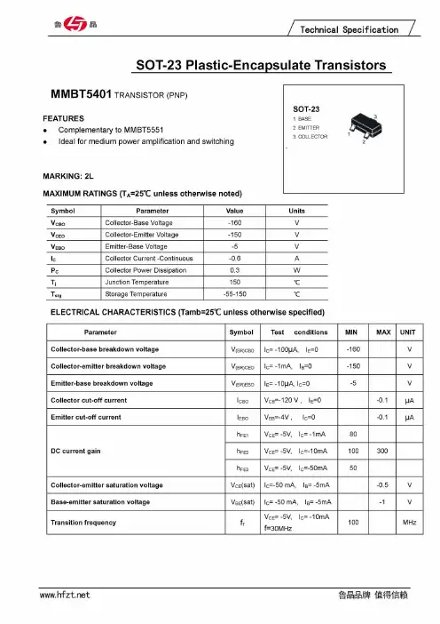

Features∙ Epitaxial Planar Die Construction ∙ Complementary NPN Type - MMBT5551 ∙ Ideal for Low Power Amplification and Switching∙ Totally Lead-Free & Fully RoHS Compliant (Notes 1 & 2) ∙ Halogen and Antimony Free. "Green" Device (Note 3) ∙ Qualified to AEC-Q101 Standards for High Reliability ∙ PPAP Capable (Note 4)Mechanical Data∙ Case: SOT23∙ Case Material: Molded Plasti c, “Green” Molding Compound ∙ UL Flammability Classification Rating 94V-0 ∙ Moisture Sensitivity: Level 1 per J-STD-020∙ Terminals: Finish – Matte Tin Plated Leads, Solderable per MIL-STD-202, Method 208 ∙Weight: 0.008 grams (Approximate)2. See https:///quality/lead-free/ for more information about Diodes Incorporated’s definitions of Halogen - and Antimony-free, "Green" andLead-free.3. Halogen and Antimony free "Green” products are defined as those which contain <900ppm bromine, <900ppm chlorine (<1500ppm tot al Br + Cl) and <1000ppm antimony compounds.4. Automotive products are AEC-Q101 qualified and are PPAP capable. Automotive, AEC-Q101 and standard products are electrically and thermallythe same, except where specified. For more information, please refer to https:///quality/.5. For packaging details, go to our website at https:///design/support/packaging/diodes-packaging/.Marking InformationTop ViewDevice SymbolTop View Pin-OutSOT23K4M = Product Type Marking CodeYM = Date Code Marking Y = Year (ex: F = 2018) M = Month (ex: 3 = March)Thermal Characteristics(@T A = +25°C, unless otherwise specified.)Notes: 6. For a device mounted on minimum recommended pad layout 1oz copper that is on a single-sided FR-4 PCB; device is measured under still air conditions whilst operating in a steady-state.7. Same as note (6), except the device is mounted on 15 mm x 15mm 1oz copper.8. Thermal resistance from junction to solder-point (at the end of the leads).9. Refer to JEDEC specification JESD22-A114 and JESD22-A115.Thermal Characteristics and Derating InformationTransient Thermal ImpedancePulse Width (s)Pulse Power DissipationPulse Width (s)MElectrical Characteristics(@T A = +25°C, unless otherwise specified.)Notes: 10. Measured under pulsed conditions. Pulse width ≤ 300µs. Duty cycle ≤ 2%.Typical Electrical Characteristics (@T A = +25°C, unless otherwise specified.)101001,0001100f , G A I N -B A N D W I D T H P R O D U C T (M H z )t I , COLLECTOR CURRENT (mA)C 0.20.30.40.50.60.70.80.91.0 V , B A S E - E M I T T E R T U R N - O N V O L T A G E ( V ) BE ( O N) I , COLLECTOR CURRENT (mA) Fig. 3 Typical Base-Emitter Turn-On Voltagevs. Collector Current CV B E (O N ), B A S E -E M I T T E R T U R N -O N V O L T A G E (V )1.0 V , C O L L E C T O R - E M I T T E R S A T U R A T I O N V OL T A G E ( V ) C E ( S A T ) I , COLLECTOR CURRENT (mA) Fig. 2 Typical Collector-Emitter Saturation Voltagevs. Collector Current CV C E (S A T ) , C O L L E C T O R -E M I T T E R S A T U R A T I O N V O L T A G E (V )1001,00010,0001101001,000 h , D C C U R R E N T G A I N F E I , COLLECTOR CURRENT (mA) Fig. 1 Typical DC Current Gain vs. Collector Current Ch F E , D C C U R R E N T G A I NPackage Outline DimensionsPlease see /package-outlines.html for the latest version.SOT23Suggested Pad LayoutPlease see /package-outlines.html for the latest version. SOT23 Note: For high voltage applications, the appropriate industry sector guidelines should be considered with regards to creepage and clearance distances betweendevice terminals and PCB tracking.All 7°。
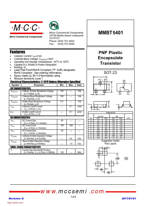
MMBT5401PNP Plastic Encapsulate TransistorFeatures• Collector Current:I CM =0.6A• Collector-Base Voltage:V (BR)CBO =160V• Operating And Storage Temperatures –55O C to 150O C • Capable of 0.3Watts of Power Dissipation • Marking:2LElectrical Characteristics @ 25OC Unless Otherwise SpecifiedSymbol ParameterMin Max Units OFF CHARACTERISTICSV (BR)CEO Coll e ctor -Emitter Breakdown Voltage (I C =1.0m Adc,I B =0)150--- Vdc V (BR)CBO Collector-Base Breakdown Voltage (I C =100uAdc,I E =0)160--- Vdc V (BR)EBO Emitter-Base Breakdown Voltage (I E =10uAdc,I C =0) 5.0--- VdcI CBO Collector Cutoff Current (V CB =120Vdc,I E =0)---0.1uAdcI EBOEmitter Cutoff Current (V EB =4.0Vdc,I C =0)---0.1uAdcON CHARACTERISTICSh FE-1DC Current Gain(V CE =5.0Vdc,I C =1.0mAdc)80------ h FE-2DC Current Gain(V CE =5.0Vdc,I C =10mAdc)100200--- h FE-3DC Current Gain(V CE =5.0Vdc,I C =50mAdc)50------V CE(sat)Collector-Emitter Saturation Voltage (I C =50mAdc,I B =5.0mAdc)---0.5Vdc V BE(sat)Base-Emitter Saturation Voltage (I C =50mAdc,I B =5.0mAdc)---1.0VdcSMALL-SIGNAL CHARACTERISTICSf TCurrent Gain-Bandwidth Product(I C =10mAdc,V CE =5.0Vdc, f=30MHz)100---MHzRevision: A 2011/01/01omp onents 20736Marilla Street Chatsworth! "# $ % ! "#Micro Commercial Componentswww.mccsemi .com1 of 2• Lead Free Finish/RoHS Compliant ("P" Suffix designates RoHS Compliant. See ordering information)• Epoxy meets UL 94 V-0 flammability rating • Moisure Sensitivity Level 1/Revision: A 2011/01/01Micro Commercial Componentswww.mccsemi .com2 of 23Ordering Information :***IMPORTANT NOTICE***Micro Commercial Components Corp. reserve s the right to make changes without further notice to any product herein to make corrections, modifications , enhancements , improvements , or other changes . Micro Commercial Components Corp . does not assume any liability arising out of the application or use of any product described herein; neither does it convey any license under its patent rights ,nor the rights of others . The user of products in such applications shall assume all risks of such use and will agree to hold Micro Commercial Components Corp . and all the companies whose products are represented on our website, harmless against all damages.***LIFE SUPPORT***MCC's products are not authorized for use as critical components in life support devices or systems without the express writtenapproval of Micro Commercial Components Corporation.***CUSTOMER AWARENESS***Counterfeiting of semiconductor parts is a growing problem in the industry. Micro Commercial Components (MCC) is taking strong measures to protect ourselves and our customers from the proliferation of counterfeit parts. MCC strongly encourages customers to purchase MCC parts either directly from MCC or from Authorized MCC Distributors who are listed by country on our web page cited below . Products customers buy either from MCC directly or from Authorized MCC Distributors are genuine parts, have full traceability, meet MCC's quality standards for handling and storage. MCC will not provide any warranty coverage or other assistance for parts bought from Unauthorized Sources. MCC is committed to combat this global problem and encourage our customers to do their part in stopping this practice by buying direct or from authorized distributors.DevicePackingPart Number-T PTape&Reel;3Kpcs/Reel/分销商库存信息: MICRO-COMMERICAL-CO MMBT5401-TP。

