STM-6308G-8 8.21说明书
- 格式:pdf
- 大小:3.82 MB
- 文档页数:42

T800 Ancillary EquipmentThis Part of the manual features a brief description of the major ancillaries that may be used with T800 series equipment. For a comprehensive list of available ancillary equip-ment, please contact your nearest approved Tait Dealer or Service Centre.T318-02 Receiver/Transmitter MonitorThe T318-02 is designed to monitor the basic operational functions of one T800 receiver and transmitter. The meter and selector switches for monitoring the required functions are mounted on the front panel, as is the monitor speaker which is driven by a built-in amplifier. An optional mute circuit may be used to silence the audio when no carrier is present.Refer to M318-02.T708-91/92 Mains Power SuppliesThe T708-91/92 mains power supplies are designed to power the T800-60 Slimline Repeater and mount on the front panel instead of the options tray. Two versions are available:T708-91 230V/50Hz mains supplyT708-92 120V/60Hz mains supply.The units are electrically the same as (although mechanically different from) the T708-01 and T708-02 respectively.Refer to M700-00 or M708-01.T800-01-001 Programming KitThe T800-01-001 kit is used for programming T800 series base station equipment and must be used in conjunction with a PC, an EPROM programming device and appropri-ate software capable of programming an EPROM from an Intel hex format or binary file. The kit comprises the following items:PGM800Win programming software user's manualPGM800Win programming software on 3" floppy discs.T800-02 CTCSS DencoderThe T800-02 CTCSS unit is designed to operate with the T800 range of receivers and transmitters. It will encode and decode CTCSS tone frequencies within the range 67 to 250.3Hz and is compatible with any other CTCSS unit which conforms to EIA RS220. Refer to TI-346.T800-03 Auxiliary D-RangeThe T800-03 is an additional D-range kit comprising 1 D-range plug assembly, 1 D-range socket and 2 locating pins, nuts & washers.T800-04 RSSIThe T800-04 RSSI option PCB plugs directly into the main PCB (support circuitry being fitted as standard). It is fitted to the T855, T875 and T885 whenever receiver signal strength monitoring is required, e.g. trunking or voting. Its function is to provide a DC voltage proportional to the signal level at the receiver input.Refer to the appropriate service manual.T800-05 Guide RailThe standard T800 series guide with one D-range socket for mounting in the standard 483mm rack frame assembly.T800-06 External Frequency Reference KitThe T800-06 kit features an additional D-range plug which incorporates a miniature RF connector to carry an externally generated 12.8MHz reference signal into a T800 mod-ule. This enables the use of very high stability external reference oscillators for special applications.T800-07 Multichannel KitThe T800-07 is a plug-in multichannel memory PCB (supplied with connecting cable) which is intended as a substitute for the T800-10 memory PCB. Up to 128 channels may be addressed via the on-board DIP switch or remotely via the T800-03 D-range kit. CTCSS frequencies may also be stored alongside channel information within the EPROM.Refer to TI-356.T800-10 Memory ModuleThe T800-10 is the standard, plug-in T800 channel memory PCB.T800-13 Extender RailThe T800-13 extender rail allows a T800 unit to be operated out of the rack with the cov-ers off for tuning purposes. It is fitted with two 15-way D-range connectors.T800-14 Extender RailThe T800-14 extender rail allows a T800 unit to be operated out of the rack with the cov-ers off for tuning purposes. It is fitted with one 15-way D-range connector and one 11-way D-range incorporating a miniature RF connector for an externally generated ref-erence signal.T800-15 Speaker PanelA 60mm speaker panel fitted with a 4Ω speaker and complete with mounting hardware.T800-16 Speaker Panel (formerly T359-01)A 120mm speaker panel fitted with a 75mm x 125mm 4Ω speaker and complete with mounting hardware.T800-19 Rack Mounting FanThe T800-19 kit features a rack mounting fan which is designed to fit into the base of any standard 483mm rack frame without affecting its ability to house 7 modules. The kit contains all mounting hardware.T800-20 Pre-wired RackThe T800-20 is a standard 5U high rack which is wired to accommodate one 25, 50 or 100W base station or repeater. It comes complete with a T800-15 speaker panel and T992-01 blank panel.T800-21 Pre-wired Rack With Interface PCBThe T800-21 is a standard 5U high rack which is wired to accommodate one 25, 50 or 100W base station or repeater. It is also fitted with an interface PCB containing a 25-way D-range to allow the easy integration of OEM products into the base station or repeater configuration. The T800-21 comes complete with a T800-15 speaker panel and T992-01 blank panel.T800-30 & T800-35 DFSK ModulatorsThe T800-30 and T800-35 are DFSK modulators for T800 transmitters, suitable for POC-SAG or similar paging data formats. Analogue transmissions (e.g. tone or speech) are still possible by disabling the data path via a control line. 512 or 1200 baud data rates are link selectable. The T800-35 is adapted for use with an external reference oscillator for simulcast transmission.Refer to TI-373.T800-60 Slimline Repeater Mounting KitThe T800-60 Slimline Repeater kit enables one T800 receiver and one T800 transmitter to be mounted horizontally side-by-side in a standard 483mm rack frame. The kit contains a front panel complete with speaker, an options tray (for mounting a power supply, duplexer, etc.), and a wiring loom to connect the two T800 modules to the terminal blocks mounted on the rear of the options tray. The T708-91/92 mains power supplies (available separately) are designed for use with the T800-60. The rack height of the assembled unit is 2U.T800-80 Local MicrophoneA 600Ω microphone complete with 300mm cord terminated in a ¼" stereo plug.T800-81 Narrow Band Conversion KitThe T800-81 kit provides the components required to convert one T835 receiver from 25kHz channel spacing to 12.5kHz channel spacing for narrow band operation.T800-82 Narrow Band Conversion KitThe T800-82 kit provides the components required to convert one T836 transmitter or one T837 exciter from 5kHz deviation to 2.5kHz deviation for narrow band operation.T800-83 Narrow Band Conversion KitThe T800-83 kit provides the components required to convert one T855 receiver from 25kHz channel spacing to 12.5kHz channel spacing for narrow band operation.T800-84 Narrow Band Conversion KitThe T800-84 kit provides the components required to convert one T856 transmitter or one T857 exciter from 5kHz deviation to 2.5kHz deviation for narrow band operation.T801 Frequency Reference ModuleThe T801 frequency reference module provides a high stability frequency source to which the synthesiser within a T800 base station can be locked. The master standard within the T801 is primarily intended to be rubidium, although high quality ovenised crystal oscillators can also be used in applications where more frequent readjustment of frequency is acceptable. The T801 converts the output frequency from its master stand-ard to the 12.8MHz required by the T800 base station.Refer to M801-00.T801-10 OCXO ModuleThe T801-10 OCXO module provides a high stability frequency source to which the syn-thesiser within a T800 base station can be locked. This will provide T800 transmitters with the frequency stability required for simulcast transmission. The master standard within the T801-10 is a high quality ovenised crystal oscillator (OCXO). Three outputs are provided on the rear panel, which allows up to three T800 transmitters to be refer-enced to the source oscillator.T802-00 Remote MonitorThe T802-00 is a microprocessor controlled remote monitor unit designed for use with Tait base station equipment. Each remote base requires one T802-00 which communi-cates via its integral modem with a centrally located PC based controller. The PC con-troller runs software to convert the raw data from the T802-00 into a user friendly form. Refer to M802-00.T802-10 RF SplitterThe T802-10 RF splitters are used to take attenuated RF from the transmitter to the T802–00 where it is mixed onto the receiver frequency by the shift mixer. This RF is then inserted via another splitter into the receiver. Each T802-10 kit contains 2 identical RF splitter modules.Refer to M802-00.T802-20 Modem & Programming KitThe T802-20 kit provides a modem and the operating software for the T802-00 remote monitor PC controller and comprises the following items:a CCITT V.23 modemT802-00 PC software user's manualT802-00 PC software on a 5¼" floppy disc.T802-21 Programming KitThe T802-21 kit provides the operating software for the T802-00 remote monitor PC con-troller and comprises the following items:T802-00 PC software user's manualT802-00 PC software on a 5¼" floppy disc.T802-22 ModemA CCITT V.23 modem for use with the T802-00 PC controller.T806 Mains Power SupplyThe T806 is a power supply capable of supplying up to 6A at 11-14V DC and is available in 2 versions to suit a mains supply of either 230V/50Hz or 115V/60Hz (nominal val-ues). The T806 is designed to power T800 series 25W transmitters (plus receivers, etc.) and comes complete with a guide to mount in a standard 60mm rack frame assembly. Refer to M806-00.T807 Mains Power SupplyThe T807 is a switching power supply capable of supplying up to 15A at 11-14V DC. It requires a mains supply of 230V/50Hz or 115V/60Hz (nominal values) which can be internally selected with a switch or wire links. The T807 is designed to power T800 series 50W transmitters (plus receivers, etc.) and comes complete with a guide to mount in a standard 60mm rack frame assembly.Refer to M807-00.T808 Mains Power SupplyThe T808 is a switching power supply capable of supplying up to 25A at 11-14V DC. It requires a mains supply of 230V/50Hz or 115V/60Hz (nominal values) which can be internally selected with a switch or wire links. The T808 is designed to power T800 series 100W transmitters (plus receivers, etc.) and comes complete with a guide to mount in a standard 60mm rack frame assembly.Refer to M807-00.T1500-50 Trunking Extra D-Range (formerly T800-50)Trunking systems require additional outputs for flat audio (FFSK) and Rx line monitor-ing. This kit provides the components to connect these outputs via a second D-range.T1500-51 Trunking Transmitter Interface (formerly T800-51)When fitted to a T800 series transmitter, the T1500-51 trunking transmitter interface PCB allows the trunking system to switch the audio processor between FFSK and normal audio. The PCB comes complete with wires, sockets and screws, but a T800-03 auxiliary D-range kit will also be required.KS820 Spares KitThe KS820 spares kit contains all the parts on the T820 series recommended spares list and is intended to provided enough spares to maintain a single installation of up to ten channels. Included in the kit are electrical and mechanical parts that are either unique to Tait equipment, hard to obtain or susceptible to damage or wear and tear. All parts are securely packed in clearly labelled screw top containers in a handy plastic carry case.Note:The kit does not contain standard chip capacitors or resistors.KS830 Spares KitThe KS830 spares kit contains all the parts on the T830 series recommended spares list and is intended to provided enough spares to maintain a single installation of up to ten channels. Included in the kit are electrical and mechanical parts that are either unique to Tait equipment, hard to obtain or susceptible to damage or wear and tear. All parts are securely packed in clearly labelled screw top containers in a handy plastic carry case.Note:The kit does not contain standard chip capacitors or resistors.KS850 Spares KitThe KS850 spares kit contains all the parts on the T850 series recommended spares list and is intended to provided enough spares to maintain a single installation of up to ten channels. Included in the kit are electrical and mechanical parts that are either unique to Tait equipment, hard to obtain or susceptible to damage or wear and tear. All parts are securely packed in clearly labelled screw top containers in a handy plastic carry case.Note:The kit does not contain standard chip capacitors or resistors.KS880 Spares KitThe KS880 spares kit contains all the parts on the T880 series recommended spares list and is intended to provided enough spares to maintain a single installation of up to ten channels. Included in the kit are electrical and mechanical parts that are either unique to Tait equipment, hard to obtain or susceptible to damage or wear and tear. All partsare securely packed in clearly labelled screw top containers in a handy plastic carry case.Note:The kit does not contain standard chip capacitors or resistors.。

安装、使用产品前,请仔细阅读使用说明书并妥善保管、备用CDMNE-400、630塑料外壳式断路器使用说明书CDMNE-400、630塑料外壳式断路器安全告知在安装、操作、运行、维护、检查之前,请务必认真阅读本说明书,并按照说明书上的内容准确安装、使用本产品。
危险:●严禁湿手操作断路器;●使用中,严禁触摸导电部位;●维护与保养时,必须确保产品不带电;●严禁用短路的办法来测试产品;注意:●安装、维护与保养时,应由具有专业资格的人员操作;●产品的各项特性出厂时已整定,使用中不能自行拆装或随意调节;●使用前请确认产品的额定电压,额定电流,频率及特性是否符合工作要求;●为防止相间短路,本产品出厂时配置相间隔板;底板和端子罩,请务必在使用中正确安装,不可漏装和不装。
同时应对接线端裸露导线或铜母线进行绝缘处理,确保绝缘安全;●如需测试绝缘电阻或工频耐压,必须先将电流回路之间的电子元件断开,否则将损坏产品性能;●如果产品在开箱时有破损或异常响声,应立即停止使用并联系供应商;●过载报警不脱扣产品不具备过载保护功能,仅适用于过载报警不脱扣场所;●如需选购附件,请选用本公司所提供的配套附件,以保证质量,如用户因使用非本公司附件而产生的一切不良后果,本公司概不负责;●产品报废时,请做好产品废弃物处理,谢谢您的合作。
测试:●本断路器出厂前已执行标准规定的绝缘测试,若安装前需复测,其步骤如下:●用1000VDC兆欧表;●绝缘电阻应不小于20MΩ;●在断路器触头间,相间,相与外壳间(外壳用金属箔覆盖);注:如用户无兆欧表,可用工频耐压测试仪做替代实验,测量部位参照绝缘测试方法,施加电压2000V/5秒钟。
请注意带部分的信息1、认识CDMNE-400、6301.1装箱单1.2产品使用环境和条件●本产品防护等级为IP30(接线端子位置为IP00)●本产品污染等级为3级●额定工作电压AC800V/AC1000V/AC1140V●安装地点海拔不应超过2000m,海拔超过2000m时的安装使用,请与制造商联系●允许环境温度-40℃~+70℃,环境温度+40℃时相对湿度不超过50%,较低温度可以有较高湿度如:25℃时相对湿度可达80%,对于因温度变化所产生的凝霜应采取相应的措施。

EDS-308Series8-port unmanaged Ethernet switchesFeatures and Benefits•Relay output warning for power failure and port break alarm •Broadcast storm protection•-40to 75°C operating temperature range (-T models)CertificationsIntroductionThe EDS-308Ethernet switches provide an economical solution for your industrial Ethernet connections.These 8-port switches come with a built-in relay warning function that alerts network engineers when power failures or port breaks occur.In addition,the switches are designed for harsh industrial environments,such as the hazardous locations defined by the Class 1Div.2and ATEX Zone 2standards.The switches comply with FCC,UL,and CE standards and support either a standard operating temperature range of 0to 60°C or a wide operating temperature range of -40to 75°C.All switches in the series undergo a 100%burn-in test to ensure that they fulfill the special needs of industrial automation control applications.The EDS-308switches can be installed easily on a DIN rail or in a distribution box.SpecificationsInput/Output InterfaceAlarm Contact Channels1relay output with current carrying capacity of 1A @24VDCEthernet Interface10/100BaseT(X)Ports (RJ45connector)EDS-308/308-T:8EDS-308-M-SC/308-M-SC-T/308-S-SC/308-S-SC-T/308-S-SC-80:7EDS-308-MM-SC/308-MM-SC-T/308-MM-ST/308-MM-ST-T/308-SS-SC/308-SS-SC-T/308-SS-SC-80:6All models support:Auto negotiation speed Full/Half duplex modeAuto MDI/MDI-X connection100BaseFX Ports (multi-mode SC connector)EDS-308-M-SC:1EDS-308-M-SC-T:1EDS-308-MM-SC:2EDS-308-MM-SC-T:2100BaseFX Ports (multi-mode ST connector)EDS-308-MM-ST:2EDS-308-MM-ST-T:2100BaseFX Ports (single-mode SC connector)EDS-308-S-SC:1EDS-308-S-SC-T:1EDS-308-SS-SC:2EDS-308-SS-SC-T:2100BaseFX Ports (single-mode SC connector,80km)EDS-308-S-SC-80:1EDS-308-SS-SC-80:2Standards IEEE802.3for10BaseTIEEE802.3u for100BaseT(X)and100BaseFXIEEE802.3x for flow controlOptical Fiber800Typical Distance4km5km40km80kmWavelen-gthTypical(nm)130013101550TX Range(nm)1260to13601280to13401530to1570 RX Range(nm)1100to16001100to16001100to1600Optical PowerTX Range(dBm)-10to-200to-50to-5 RX Range(dBm)-3to-32-3to-34-3to-34 Link Budget(dB)122929 Dispersion Penalty(dB)311Note:When connecting a single-mode fiber transceiver,we recommend using anattenuator to prevent damage caused by excessive optical power.Note:Compute the“typical distance”of a specific fiber transceiver as follows:Linkbudget(dB)>dispersion penalty(dB)+total link loss(dB).DIP Switch ConfigurationEthernet Interface Port break alarmSwitch PropertiesMAC Table Size2kbitsPacket Buffer Size768KProcessing Type Store and ForwardPower ParametersInput Current EDS-308/308-T:0.07A@24VDCEDS-308-M-SC/S-SC Series,308-S-SC-80:0.12A@24VDCEDS-308-MM-SC/MM-ST/SS-SC Series,308-SS-SC-80:0.15A@24VDC Connection1removable6-contact terminal block(s)Operating Voltage9.6to60VDCInput Voltage Redundant dual inputs,12/24/48VDCReverse Polarity Protection SupportedOverload Current Protection SupportedPhysical CharacteristicsHousing MetalIP Rating IP30Dimensions53.6x135x105mm(2.11x5.31x4.13in)Weight790g(1.75lb)Installation DIN-rail mounting,Wall mounting(with optional kit) Environmental LimitsOperating Temperature Standard Models:-10to60°C(14to140°F)Wide Temp.Models:-40to75°C(-40to167°F) Storage Temperature(package included)-40to85°C(-40to185°F)Ambient Relative Humidity5to95%(non-condensing)Standards and CertificationsHazardous Locations ATEX,Class I Division2EMI CISPR32,FCC Part15B Class AMaritime DNV-GLEMC EN55032/24Vibration IEC60068-2-6EMS IEC61000-4-2ESD:Contact:6kV;Air:8kVIEC61000-4-3RS:80MHz to1MHz:20V/mIEC61000-4-4EFT:Power:2kV;Signal:1kVIEC61000-4-5Surge:Power:2kV;Signal:2kVIEC61000-4-6CS:10VIEC61000-4-8PFMFSafety UL508,UL60950-1,CSA C22.2No.60950-1 Shock IEC60068-2-27Freefall IEC60068-2-32MTBFTime255,528hrsStandards MIL-HDBK-217FWarrantyWarranty Period5yearsDetails See /warrantyPackage ContentsDevice1x EDS-308Series switchInstallation Kit1x cap,plastic,for SC fiber port2x cap,plastic,for SC fiber port(-SC models)2x cap,plastic,for ST fiber port(-ST models) Documentation1x quick installation guide1x warranty cardDimensionsOrdering InformationModel Name 10/100BaseT(X)PortsRJ45Connector100BaseFX PortsMulti-Mode,SCConnector100BaseFX PortsMulti-Mode,STConnector100BaseFX PortsSingle-Mode,SCConnectorOperating Temp.EDS-3088–––0to60°CEDS-308-T8–––-40to75°C EDS-308-M-SC71––0to60°CEDS-308-M-SC-T71––-40to75°C EDS-308-MM-SC62––0to60°CEDS-308-MM-SC-T62––-40to75°C EDS-308-MM-ST6–2–0to60°CEDS-308-MM-ST-T6–2–-40to75°C EDS-308-S-SC7––10to60°CEDS-308-S-SC-T7––1-40to75°C EDS-308-SS-SC6––20to60°CEDS-308-SS-SC-T6––2-40to75°C EDS-308-S-SC-807––10to60°CEDS-308-SS-SC-806––20to60°C Accessories(sold separately)Power SuppliesDR-120-24120W/2.5A DIN-rail24VDC power supply with universal88to132VAC or176to264VAC input byswitch,or248to370VDC input,-10to60°C operating temperatureDR-452445W/2A DIN-rail24VDC power supply with universal85to264VAC or120to370VDC input,-10to50°C operating temperatureDR-75-2475W/3.2A DIN-rail24VDC power supply with universal85to264VAC or120to370VDC input,-10to60°C operating temperatureMDR-40-24DIN-rail24VDC power supply with40W/1.7A,85to264VAC,or120to370VDC input,-20to70°Coperating temperatureMDR-60-24DIN-rail24VDC power supply with60W/2.5A,85to264VAC,or120to370VDC input,-20to70°Coperating temperatureWall-Mounting KitsWK-46Wall-mounting kit,2plates,8screws,46.5x66.8x1mmRack-Mounting KitsRK-4U19-inch rack-mounting kit©Moxa Inc.All rights reserved.Updated Jan30,2019.This document and any portion thereof may not be reproduced or used in any manner whatsoever without the express written permission of Moxa Inc.Product specifications subject to change without notice.Visit our website for the most up-to-date product information.。

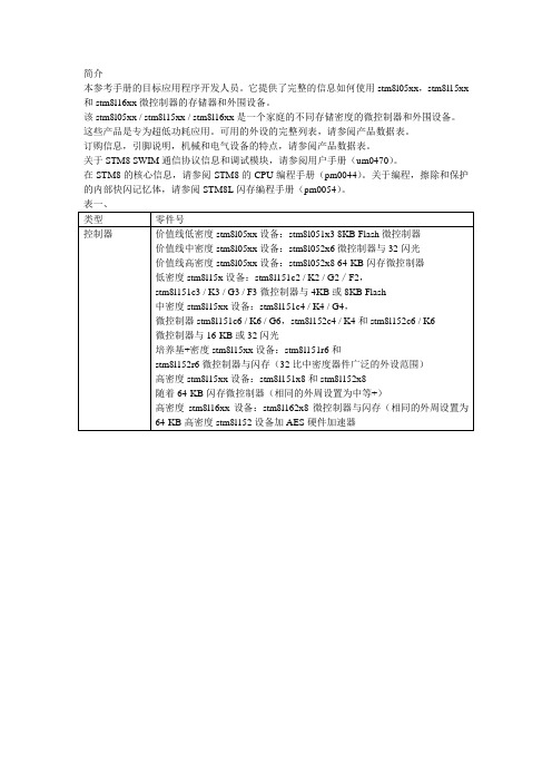
本参考手册的目标应用程序开发人员。
它提供了完整的信息如何使用stm8l05xx,stm8l15xx 和stm8l16xx微控制器的存储器和外围设备。
该stm8l05xx / stm8l15xx / stm8l16xx是一个家庭的不同存储密度的微控制器和外围设备。
这些产品是专为超低功耗应用。
可用的外设的完整列表,请参阅产品数据表。
订购信息,引脚说明,机械和电气设备的特点,请参阅产品数据表。
关于STM8 SWIM通信协议信息和调试模块,请参阅用户手册(um0470)。
在STM8的核心信息,请参阅STM8的CPU编程手册(pm0044)。
关于编程,擦除和保护的内部快闪记忆体,请参阅STM8L闪存编程手册(pm0054)。
1 中央处理单元(CPU)。
30。
1.1 引言301.2 CPU的寄存器。
30。
1.2.1 描述CPU寄存器。
..。
301.2.2 STM8 CPU寄存器图。
..。
341.3 全球配置寄存器(cfg_gcr)。
34。
1.3.1 激活水平。
..。
341.3.2 游泳禁用。
..。
351.3.3 描述全局配置寄存器(cfg_gcr)。
..。
35 1.3.4 全局配置寄存器图及复位值。
..。
352 启动ROM . . . 363程序存储器和数据存储器。
37。
3.1引言373.2术语。
37。
3.3个主要的快闪存储器的特点。
38。
3.4记忆的组织。
39。
3.4.1低密度设备的存储器组织。
393.4.2介质密度的装置记忆的组织。
..。
403.4.3介质+密度装置记忆的组织。
..。
413.4.4高密度存储器组织。
..。
423.4.5专有代码区(译)。
433.4.6用户区(UBC)。
433.4.7数据的EEPROM(数据)。
..。
463.4.8主程序区。
463.4.9选项字节。
..。
463.5内存保护。
47。
3.5.1读出保护。
473.5.2内存访问安全系统(质量)。
473.5.3使写访问选项字节。
493.6内存编程493.6.1同时读写(读写网)。

T850 Series II Base Station Equipment400-520MHzService ManualIssue 202March 2000M850-00-202Head OfficeNew ZealandTait Electronics Ltd558 Wairakei RoadP.O. Box 1645ChristchurchNew ZealandPhone: 64 3 358 3399Fax: 64 3 358 3903Radio Systems Division535 Wairakei RoadP.O. Box 1645ChristchurchNew ZealandPhone: 64 3 358 3399Fax: 64 3 358 6486AustraliaTait Electronics (Aust) Pty Ltd 186 Granite StreetGeebungQueensland 4034P.O. Box 679VirginiaQueensland 4014AustraliaPhone: 61 7 3865 7799Toll Free: 1 800 077 112 Fax: 61 7 3865 7990BeijingTait Mobile Radio (HK) Ltd Beijing Representative Office Room 610, Tower 2Beijing Henderson Centre No. 18 Jianguomennei Da Jie Doncheng DistrictBeijingChina 100005CanadaTait Mobile Radio Inc.Unit 5, 158 Anderson AvenueMarkhamOntario L6E 1A9CanadaPhone: 1 905 472 1100TollFree:180****8248Fax: 1 905 472 5300FranceTait France Sarl2 Avenue de la Cristallerie92 316 Sèvres, CedexFrancePhone: 33 1 41 14 05 50Fax: 33 1 41 14 05 55GermanyTait Europe LimitedGeschäftsstelle DeutschlandFürther Str. 27D-90429 NürnbergGermanyPhone: 49 911 2870 7064Fax: 49 911 2870 7160Hong KongTait Mobile Radio (HK) LtdUnit 2216, North TowerConcordia PlazaNo. 1 Science Museum RoadTsim Sha Tsui EastKowloonPhone: 852 2369 3040Fax: 852 2369 3009New ZealandTait Communications LtdUnit 4, 75 Blenheim RoadP.O. Box 1185ChristchurchPhone: 64 3 348 3301Fax: 64 3 343 0558SingaporeTait Electronics (Far East) Pte Ltd4 Leng Kee RoadSIS Building #05-11ASingapore 159088Phone: 65 471 2688Fax: 65 479 7778TaiwanTait Mobile Radio (Taiwan) Ltd5Fl., No. 159, Keelung RdSec. 1Taipei 110TaiwanPhone: 886 2 2768 6600Fax: 886 2 2761 9970ThailandTait Mobile Radio Ltd14/1 Suwan TowerThird FloorNorth Sathorn RoadSoi Saladaeng 1BangrakBangkok 10500ThailandPhone: 662 267 6290Fax: 662 267 6293United KingdomTait Europe LtdErmine Business ParkErmine RoadHuntingdonCambridgeshire PE18 6YAUnited KingdomPhone: 44 1480 52 255Fax: 44 1480 411 996USATait Electronics (USA) Inc.9434 Old Katy RoadSuite 110HoustonTexas 77055USAPhone:171****8684TollFree:180****1255Fax:171****6944InternetT800 T800About This ManualScope This manual contains general, technical and servicing informa-tion on T850 Series II 25W, 50W and 100W base stations whichcomprise the following equipment:Format We have published this manual in a ring binder so that "revisionpackages" containing additional information pertaining to newissues of PCBs can be added as required.Revision Packages Revision packages will normally be published to coincide withthe release of information on a new PCB, and may also containadditions or corrections pertaining to other parts of the manual.You may order as many packages as you require from your localTait Dealer or Customer Service Organisation. Revision pack-ages are supplied ready-punched for inclusion in your manual.Revision Control Each page in this manual has a date of issue. This is to complywith various Quality Standards, but will also serve to identifywhich pages have been updated and when. Each page and itspublication date is listed in the "List of Effective Pages", and anew list containing any new/revised pages and their publica-tion dates will be sent with each revision package.Any portion of text that has been changed is marked by a verti-cal line (as shown at left) in the outer margin of the page or col-umn. Where the removal of an entire paragraph means there isno text left to mark, an arrow (as shown at left) will appear inthe outer margin. The number beside the arrow will indicatehow many paragraphs have been deleted. Changes to diagramsthat cannot be marked by these methods will be explained in anAmendments Box added to the diagram.The manual issue and revision status are indicated by the lastthree digits of the manual product code. These digits start at 200and will increment through 201, 202, 203, etc., as revision pack-ages are published, e.g: 25W base station T855 receiverT856 25W transmitter 50W base station T855 receiverT857 exciterT858 50W power amplifier100W base station T855 receiverT857 exciter T859 100W power amplifier2 2 0 3issue status revision statusThus, issue 203 indicates the third revision to issue 2 and meansthat three packages should have been added to the manual. Theissue digit will only change if there is a major product revision,or if the number of revision packages to be included means thatthe manual becomes difficult to use, at which point a new issuemanual will be published in a new ring binder.PCB Information PCB information is provided for all current issue PCBs, as wellas all previous issue PCBs manufactured in production quanti-ties, and is grouped according to PCB. Thus, you will find theparts list, grid reference index (if necessary), PCB layouts andcircuit diagram(s) for each individual PCB grouped together. Errors If you find an error in this manual, or have a suggestion on howit might be improved, please do not hesitate to contact CustomerSupport, Radio Systems Division, Tait Electronics Ltd, Christch-urch, New Zealand (full contact details are on page 2). Updating Equipment And ManualsIn the interests of improving performance, reliability or servicing, Tait Electronics Ltd reserve the right to update their equipment and/or manuals without prior notice. CopyrightAll information contained in this manual is the property of Tait Electronics Ltd. All rights are reserved. This manual may not, in whole or part, be copied, photocopied, reproduced, translated stored or reduced to any electronic medium or machine readable form without prior written permission from Tait Electronics Ltd.Ordering Tait Service ManualsYou can order additional copies of this service manual from your nearest Tait Dealer or Customer Service Organisation. When ordering, make sure you quote the correct Tait product code ("M" number). Note that only the latest issue of the manual will be availa-ble for order.Publication InformationT850 Series II Service ManualIssue Publication Date Product Code Incorporates Revision Package200 201 202October 1998February 1999March 2000M850-00-200M850-00-201M850-00-202—R850-00-201R850-00-202Table Of ContentsThis manual is divided into nine parts as listed below, with each part being further sub-divided into sections. There is a detailed table of contents at the start of each part and/ or section.Part TitleA Introduction To ServicingB T855 ReceiverC T856 Transmitter & T857 ExciterD T858 & T859 Power AmplifiersE T850 VCO PCB InformationF InstallationG System ConfigurationsH T800 Ancillary EquipmentI Using T850 Series II Equipment In A Series I Rack FrameList Of Effective PagesThe total number of pages in this Manual is 568, as listed below. Page Issue Date Page Issue Date129/02/00229/02/00331/01/99429/02/00531/09/98629/02/00729/02/00829/02/00929/02/001029/02/001129/02/001229/02/00Part AI29/02/00II31/09/98(blank) 1.131/09/981.231/09/982.131/09/982.231/09/982.331/01/992.429/02/003.131/09/983.231/09/984.131/09/984.231/09/98Part BI31/09/98II31/09/98(blank) 1.131/09/981.231/09/98(blank) 1.331/09/98(fold-out) 1.431/09/98(fold-out) 1.531/09/981.631/09/981.729/02/001.829/02/001.929/02/001.1031/09/981.1131/09/981.1231/09/981.1331/09/981.1431/09/98(blank)2.131/09/982.231/09/98(blank)2.331/09/982.429/02/002.531/09/982.631/09/982.731/09/982.829/02/002.929/02/002.1031/09/982.1131/09/982.1231/09/983.131/09/983.231/09/983.331/09/983.431/09/983.529/02/003.629/02/003.729/02/003.831/01/993.931/09/983.1029/02/003.1129/02/003.1229/02/003.1329/02/003.1429/02/004.131/09/984.231/09/98(blank)4.329/02/004.431/09/984.531/09/984.631/09/984.731/09/984.831/09/98(blank)4.931/09/98(fold-out)4.1031/09/98(fold-out)(blank)Page Issue Date Page Issue Date5.131/09/985.231/09/985.331/09/985.431/09/985.531/09/985.629/02/005.731/09/985.831/09/985.931/09/985.1031/09/985.1131/09/985.1231/09/985.1331/09/985.1431/09/985.1531/09/985.1631/09/985.1731/09/985.1831/09/985.1931/09/985.2031/09/98(blank)6.1.131/01/996.1.231/09/98(blank)6.1.331/09/986.1.431/09/986.1.529/02/006.1.631/09/986.2.131/09/986.2.231/09/98(blank)6.2.329/02/006.2.431/09/986.2.531/09/986.2.631/09/986.2.731/09/98(fold-out)6.2.831/09/98(fold-out)(blank) 6.3.131/01/996.3.231/09/98(blank)6.3.331/01/996.3.431/09/986.3.531/09/986.3.631/09/986.3.731/09/986.3.831/09/986.3.931/09/98(blank)6.3.1031/09/986.3.1131/09/98(fold-out)6.3.1231/09/98(fold-out)(blank) 6.3.1331/09/986.3.1431/09/986.3.1531/09/986.3.1631/09/98(blank)6.3.1731/09/98(fold-out)6.3.1831/09/98(fold-out)6.3.1931/09/98(fold-out)6.3.2031/09/98(fold-out)6.3.2131/09/98(fold-out)6.3.2231/09/98(fold-out)6.3.2331/09/98(fold-out)6.3.2431/09/98(fold-out)6.3.2531/09/98(fold-out)6.3.2631/09/98(fold-out)6.3.2731/09/98(fold-out)6.3.2829/02/00(fold-out)6.3.2931/09/98(fold-out)6.3.3031/09/98(fold-out)(blank) 6.3.3129/02/006.3.3231/01/996.3.3331/01/996.3.3431/01/996.3.3531/01/996.3.3631/01/996.3.3731/01/99(blank)6.3.3831/01/996.3.3931/01/99(fold-out)6.3.4031/01/99(fold-out)(blank) 6.3.4131/01/996.3.4231/01/996.3.4331/01/996.3.4431/01/99(blank)6.3.4531/01/99(fold-out)6.3.4631/01/99(fold-out)6.3.4731/01/99(fold-out)6.3.4831/01/99(fold-out)6.3.4931/01/99(fold-out)6.3.5031/01/99(fold-out)6.3.5131/01/99(fold-out)6.3.5231/01/99(fold-out)6.3.5331/01/99(fold-out)6.3.5431/01/99(fold-out)6.3.5531/01/99(fold-out)6.3.5631/01/99(fold-out)6.3.5731/01/99(fold-out)6.3.5831/01/99(fold-out)(blank) Part CI31/09/98II31/09/98(blank)1.131/09/981.231/09/98(blank)Page Issue Date Page Issue Date1.331/09/98(fold-out) 1.431/09/98(fold-out) 1.531/09/98(fold-out) 1.631/09/98(fold-out) 1.731/09/981.829/02/001.929/02/001.1029/02/001.1129/02/001.1229/02/001.1329/02/001.1429/02/001.1529/02/001.1631/09/98(blank)2.131/09/982.231/09/982.331/09/982.429/02/002.531/09/982.629/02/002.731/09/982.829/02/002.929/02/002.1029/02/002.1129/02/002.1231/09/982.1329/02/002.1431/09/98(blank)3.129/02/003.229/02/003.331/09/983.431/09/983.529/02/003.629/02/003.729/02/003.831/09/983.931/09/983.1031/09/983.1129/02/003.1229/02/003.1329/02/003.1429/02/004.131/09/984.231/09/98(blank) 4.331/09/984.429/02/004.529/02/004.631/09/984.731/09/984.831/09/98(blank)4.931/09/98(fold-out)4.1031/09/98(fold-out)(blank) 4.1131/09/98(fold-out)4.1231/09/98(fold-out)(blank)5.131/09/985.231/09/985.331/09/985.431/09/985.531/09/985.631/09/985.731/09/985.831/09/985.931/09/985.1031/09/985.1131/09/985.1231/09/985.1331/09/985.1431/09/985.1531/09/985.1631/09/985.1731/09/985.1831/09/985.1931/09/985.2029/02/006.1.129/02/006.1.231/09/98(blank)6.1.331/09/986.1.431/09/986.1.529/02/006.1.631/09/986.2.131/09/986.2.231/09/98(blank)6.2.329/02/006.2.431/09/986.2.531/09/986.2.631/09/986.2.731/09/986.2.831/09/986.2.929/02/006.2.1031/09/986.2.1131/09/98(fold-out)6.2.1231/09/98(fold-out)(blank) 6.2.1331/09/986.2.1431/09/986.2.1531/09/986.2.1631/09/986.2.1731/09/98(fold-out)6.2.1831/09/98(fold-out)Page Issue Date Page Issue Date6.2.1931/09/98(fold-out)6.2.2031/09/98(fold-out)6.2.2131/09/98(fold-out)6.2.2231/09/98(fold-out)6.2.2331/09/98(fold-out)6.2.2431/09/98(fold-out)6.2.2531/09/98(fold-out)6.2.2631/09/98(fold-out)6.2.2731/09/98(fold-out)6.2.2831/01/99(fold-out)6.2.2931/09/98(fold-out)6.2.3031/09/98(fold-out)(blank) 6.3.129/02/006.3.231/09/98(blank)6.3.329/02/006.3.431/09/986.3.531/09/986.3.631/09/986.3.729/02/006.3.831/09/986.3.931/09/98(fold-out)6.3.1031/09/98(fold-out)(blank) 6.3.1131/09/986.3.1231/09/986.3.1331/09/986.3.1431/09/98(blank)6.3.1531/09/98(fold-out)6.3.1631/09/98(fold-out)6.3.1731/09/98(fold-out)6.3.1831/09/98(fold-out)6.3.1931/09/98(fold-out)6.3.2031/09/98(fold-out)6.3.2131/09/98(fold-out)6.3.2231/09/98(fold-out)6.3.2331/09/98(fold-out)6.3.2431/09/98(fold-out)6.3.2531/09/98(fold-out)6.3.2629/02/00(fold-out)6.3.2731/09/98(fold-out)6.3.2831/09/98(fold-out)(blank) 6.3.2929/02/006.3.3029/02/006.3.3129/02/006.3.3229/02/006.3.3329/02/006.3.3429/02/006.3.3529/02/006.3.3629/02/006.3.3729/02/00(fold-out)6.3.3829/02/00(fold-out)(blank) 6.3.3929/02/006.3.4029/02/006.3.4129/02/006.3.4229/02/00(blank)6.3.4329/02/00(fold-out)6.3.4429/02/00(fold-out)6.3.4529/02/00(fold-out)6.3.4629/02/00(fold-out)6.3.4729/02/00(fold-out)6.3.4829/02/00(fold-out)6.3.4929/02/00(fold-out)6.3.5029/02/00(fold-out)6.3.5129/02/00(fold-out)6.3.5229/02/00(fold-out)6.3.5329/02/00(fold-out)6.3.5429/02/00(fold-out)6.3.5529/02/00(fold-out)6.3.5629/02/00(fold-out)(blank) Part DI29/02/00II31/09/98(blank)1.129/02/001.229/02/00(blank)1.329/02/001.429/02/00(blank)1.529/02/00(fold-out)1.629/02/00(fold-out)1.729/02/00(fold-out)1.829/02/00(fold-out)1.929/02/00(fold-out)1.1029/02/00(fold-out)1.1129/02/00(fold-out)1.1229/02/00(fold-out)1.1329/02/001.1429/02/001.1529/02/001.1629/02/001.1729/02/001.1829/02/002.129/02/002.229/02/002.329/02/002.429/02/002.529/02/002.629/02/002.729/02/002.829/02/002.929/02/00Page Issue Date Page Issue Date2.1029/02/002.1129/02/002.1229/02/002.1329/02/002.1429/02/002.1529/02/002.1629/02/00(blank)3.129/02/003.229/02/003.329/02/003.429/02/003.529/02/003.629/02/003.729/02/003.829/02/003.929/02/003.1029/02/003.1129/02/003.1229/02/003.1329/02/003.1429/02/00(blank)3.1529/02/00(fold-out)3.1629/02/00(fold-out)(blank) 3.1729/02/00(fold-out)3.1829/02/00(fold-out)(blank) 3.1929/02/00(fold-out)3.2029/02/00(fold-out)(blank) 3.2129/02/00(fold-out)3.2229/02/00(fold-out)(blank)4.129/02/004.229/02/004.329/02/004.429/02/004.529/02/00(fold-out)4.629/02/00(fold-out)(blank) 4.729/02/004.829/02/004.929/02/004.1029/02/004.1129/02/004.1229/02/004.1329/02/004.1429/02/004.1529/02/004.1629/02/004.1729/02/004.1829/02/004.1929/02/004.2029/02/00(blank)4.2129/02/00(fold-out)4.2229/02/00(fold-out)4.2329/02/004.2429/02/004.2529/02/004.2629/02/004.2729/02/004.2829/02/004.2929/02/004.3029/02/004.3129/02/004.3229/02/005.1.129/02/005.1.231/09/98(blank)5.1.331/09/985.1.431/09/985.1.529/02/005.1.631/09/985.2.129/02/005.2.231/09/98(blank)5.2.329/02/005.2.429/02/005.2.531/09/985.2.631/09/985.2.731/09/98(blank)5.2.831/09/985.2.931/09/98(fold-out)5.2.1031/09/98(fold-out)(blank) 5.2.1131/09/985.2.1231/09/98(blank)5.2.1331/09/98(fold-out)5.2.1431/09/98(fold-out)5.2.1531/09/98(fold-out)5.2.1631/09/98(fold-out)5.2.1729/02/005.2.1829/02/005.2.1929/02/005.2.2029/02/005.2.2129/02/00(blank)5.2.2229/02/005.2.2329/02/00(fold-out)5.2.2429/02/00(fold-out)(blank) 5.2.2529/02/005.2.2629/02/005.2.2729/02/00(fold-out)5.2.2829/02/00(fold-out)5.2.2929/02/00(fold-out)5.2.3029/02/00(fold-out)5.3.129/02/005.3.231/09/98(blank)M850-001129/02/00Page Issue Date Page Issue Date5.3.329/02/005.3.429/02/005.3.531/09/985.3.631/09/985.3.731/09/98(blank)5.3.831/09/985.3.931/09/98(fold-out)5.3.1031/09/98(fold-out)(blank)5.3.1131/09/985.3.1231/09/985.3.1331/09/98(fold-out)5.3.1431/09/98(fold-out)5.3.1531/09/98(fold-out)5.3.1631/09/98(fold-out)5.3.1729/02/005.3.1829/02/005.3.1929/02/005.3.2029/02/005.3.2129/02/00(blank)5.3.2229/02/005.3.2329/02/00(fold-out)5.3.2429/02/00(fold-out)(blank)5.3.2529/02/005.3.2629/02/005.3.2729/02/00(fold-out)5.3.2829/02/00(fold-out)5.3.2929/02/00(fold-out)5.3.3029/02/00(fold-out)Part EI 29/02/00II 31/09/98(blank)1.131/09/981.231/09/982.131/09/982.231/09/98(blank)2.329/02/002.431/09/982.531/09/982.631/09/982.731/09/98(fold-out)2.831/09/98(fold-out)(blank)Part F I 29/02/00II 31/01/99 1.131/09/98(fold-out)1.229/02/00(fold-out)2.131/09/98(fold-out)2.229/02/00(fold-out)3.131/01/99(fold-out)3.229/02/00(fold-out)4.131/01/994.231/01/99Part GI 31/09/98II 31/09/981.131/09/981.229/02/001.331/09/981.431/09/98(blank)2.131/09/982.231/09/982.331/09/982.431/09/98(blank)3.131/09/983.231/09/98(blank)4.131/09/984.231/09/985.131/09/985.231/09/98Part HI 31/09/98II 31/09/98(blank)131/09/98231/09/98331/09/98431/09/98531/09/98631/09/98731/09/98831/09/98931/09/9812M850-00Page Issue Date Page Issue Date1031/09/981131/09/981231/09/981331/09/981431/09/98Part II29/02/00II31/09/98(blank)1.131/09/981.231/09/98(blank)2.131/09/982.231/09/982.331/09/982.431/09/982.531/09/982.631/09/982.731/09/982.831/09/98(blank)3.129/02/003.229/02/003.331/09/983.431/09/98(blank)3.529/02/003.629/02/003.729/02/003.829/02/0029/02/00。
KEY SPECIFICATIONSISOLATEDPOWER SYSTEMS• Individually shrouded contacts for electrical and mechanical protection • .100" (2.54 mm) and .165" (4.19 mm) pitch • Surface mount or through-hole• Vertical and right-angle for parallel, perpendicular and coplanar applications • Locking clip, key polarization and guide post options • Discrete wire assemblies with 16-30 AWG PVC or T eflon ™ fluoropolymer wire (see pages 243-245).• Metal or plastic rugged latching systemFEATURES & BENEFITS*Teflon ™ is a trademark of The Chemours Company FC, LLCused under license by Samteccreepage and clearance requirements.Flexible standard orhigh-power stacking systems with Power Eye three-finger BeCu contacts for reliableconnection. For available series, visit /flexiblestripsSelectively loading contacts achieves customer specific creepage and clearance requrements./minimate or /powermate-1-----05101520 25(Standard Sizes)Specify LEAD STYLE from chart–L= 10 µ" (0.25 µm) Gold on contact, Matte Tin on tailRequires -01 Lead Style (Leave blank for Through-hole)–RA = Right-angle –VS= Surface Mount–A= Alignment Pin (–VS only) (N/A with –LC)–LC = Locking Clip(Manual placement required) (–VS only) (N/A with –A)–K= (6.00 mm) .236" DIAPolyimide film Pick & Place Pad(–VS only)–TR= Tape & Reel (–VS only)–FR= Full Reel Tape & Reel (must order max. quantity per reel; contact Samtec for quantity breaks)(-VS only)IPS1-1NO. PINS PER ROW-01-PLATING OPTION-D-TAIL OPTION-OTHER OPTIONS05101520 25(Standard Sizes)–L= 10 µ" (0.25 µm) Gold on contact, Matte Tin on tailLeave blank for Through-hole –RA = Right-angle –VS–LC= Locking Clip (Manual placementrequired) (–VS only) –K= (5.50 mm) .217" DIAPolyimide film Pick & Place Pad(–VS only)–TR= Tape & Reel (–VS only)–FR= Full Reel Tape & Reel (must order max. quantity per reel; contact Samtec for quantity breaks)(-VS only)Note:Some lengths, styles and options are non-standard, non-returnable.IPT1Board Mates:IPS1IPS1Board Mates:IPT1(2.54 mm) .100" PITCH • SHROUDED POWER CONNECTOR SET View complete specifications at: ?IPT1 & ?IPS1Surface MountThrough-hole 5.9F-224/minimate。
Dell SD630-S —专为 Scality RING 设计的存储用户手册注、小心和警告:“注”表示可以帮助您更好地使用计算机的重要信息。
:“小心”表示可能会损坏硬件或导致数据丢失,并说明如何避免此类问题。
:“警告”表示可能会造成财产损失、人身伤害甚至死亡。
版权所有 © 2016 Dell Inc. 保留所有权利。
本产品受美国、国际版权和知识产权法律保护。
Dell 和 Dell 徽标是 Dell Inc. 在美国和/或其他管辖区域的商标。
所有此处提及的其他商标和名称可能是其各自所属公司的商标。
章 1: Dell SD630-S 概览 (7)支持的配置 (7)前面板 (7)8 x 2.5 英寸硬盘驱动器机箱 (7)LCD 面板 (9)背面板 (10)双提升板机箱 (10)硬盘驱动器指示灯代码 (12)iDRAC Direct LED 指示灯代码 (12)NIC 指示灯代码 (14)电源设备指示灯代码 (14)快速同步指示灯代码 (17)找到您的系统服务标签 (17)章 2: 说明文件资源 (18)章 3: 技术规格 (19)机箱尺寸 (19)机箱重量 (20)处理器规格 (20)PSU 规格 (20)系统电池规格 (20)扩展总线规格 (20)内存规格 (21)驱动器规格 (21)硬盘驱动器 (21)光盘驱动器 (21)端口和连接器规格 (21)USB 端口 (21)NIC 端口 (22)串行连接器 (22)VGA 端口 (22)视频规格 (22)环境规格 (22)微粒和气体污染规格 (23)标准操作温度 (24)扩展操作温度 (24)扩展操作温度限制 (25)章 4: 初始系统设置和配置 (26)设置系统 (26)iDRAC 配置 (26)用于设置 iDRAC IP 地址的选项 (26)目录3下载固件和驱动程序的方法 (27)管理系统 (27)章 5: 预操作系统管理应用程序 (29)用于管理预操作系统应用程序的选项 (29)系统设置 (29)查看系统设置程序 (29)系统设置程序详细信息 (30)System BIOS(系统 BIOS) (30)iDRAC 设置公用程序 (53)Device Settings(设备设置) (54)Dell Lifecycle Controller (54)嵌入式系统管理 (54)引导管理器 (54)查看引导管理器 (55)引导管理器主菜单 (55)PXE 引导 (56)章 6: 安装和卸下系统组件 (57)安全说明 (57)拆装计算机内部组件之前 (58)拆装计算机内部组件之后 (58)建议工具 (58)前挡板(可选) (59)卸下可选的前挡板 (59)安装可选的前挡板 (60)卸下系统护盖 (61)安装系统护盖 (62)系统内部 (63)冷却导流罩 (65)卸下冷却导流罩 (65)安装冷却导流罩 (65)系统内存 (66)一般内存模块安装原则 (68)模式特定原则 (68)内存配置示例 (69)卸下内存模块 (71)安装内存模块 (72)硬盘驱动器 (74)卸下 2.5 英寸硬盘驱动器挡片 (74)安装 2.5 英寸硬盘驱动器挡片 (74)卸下热插拔硬盘驱动器或 SSD (75)安装热插拔硬盘驱动器 (76)从硬盘驱动器托盘中卸下硬盘驱动器 (77)将热插拔硬盘驱动器安装到热插拔硬盘驱动器托盘中 (78)光盘驱动器(可选) (78)卸下可选光盘驱动器 (78)4目录安装细长型光盘驱动器挡片 (81)冷却风扇 (82)卸下冷却风扇 (82)安装冷却风扇 (83)内部 USB 存储钥匙(可选) (84)安装可选的内置 USB 存储盘 (84)扩展卡和扩展卡提升板 (85)扩展卡安装原则 (86)卸下扩展卡 (86)安装扩展卡 (87)卸下扩展卡提升板 (88)安装扩展卡提升板 (90)SD vFlash 介质卡(可选) (91)装回 SD vFlash 卡 (91)集成存储控制器卡 (92)卸下集成存储控制器卡 (92)安装集成存储控制器卡 (94)网络子卡 (95)卸下网络子卡 (95)安装网络子卡 (96)处理器和散热器 (97)卸下处理器 (98)安装处理器 (100)电源设备 (102)热备用功能 (102)卸下电源设备挡片 (102)安装电源设备挡片 (103)卸下交流电源设备 (104)安装交流电源设备 (104)直流电源设备的布线说明 (105)卸下直流电源设备 (106)安装直流电源设备 (107)系统电池 (108)更换系统电池 (108)硬盘驱动器背板 (109)卸下硬盘驱动器背板 (109)安装硬盘驱动器背板 (111)控制面板部件 (112)卸下控制面板的线路板 - 8 硬盘驱动器系统 (112)安装控制面板的线路板 - 8 硬盘驱动器系统 (113)VGA 模块 (114)卸下 VGA 模块 (114)安装 VGA 模块 (115)系统板 (116)卸下系统板 (116)安装系统板 (118)受信平台模块 (121)目录5为 TXT 用户初始化 TPM (122)章 7: 使用系统诊断程序 (124)Dell 嵌入式系统诊断程序 (124)何时使用 Embedded System Diagnostics(嵌入式系统诊断程序) (124)从引导管理器运行嵌入式系统诊断程序 (124)从 Dell Lifecycle Controller 运行嵌入式系统诊断程序 (124)系统诊断程序控制 (125)章 8: 跳线和连接器 (126)系统板跳线设置 (126)系统板跳线和连接器 (127)禁用已忘记的密码 (129)章 9: 系统故障排除 (130)系统启动失败故障排除 (130)外部连接故障排除 (130)视频子系统故障排除 (131)USB 设备故障排除 (131)iDRAC Direct 故障排除(USB XML 配置) (132)iDRAC Direct 故障排除(笔记本电脑连接) (132)串行 I/O 设备故障排除 (133)NIC 故障排除 (133)受潮系统故障排除 (133)受损系统故障排除 (134)系统电池故障排除 (135)电源设备故障排除 (135)电源问题故障排除 (135)电源设备故障 (136)冷却问题故障排除 (136)冷却风扇故障排除 (137)系统内存故障排除 (137)内部 U 盘故障排除 (138)光盘驱动器故障排除 (138)磁带备份装置故障排除 (139)硬盘驱动器故障排除 (139)存储控制器故障排除 (140)扩展卡故障排除 (141)处理器故障排除 (141)章 10: 获得帮助 (143)联系 Dell (143)说明文件反馈 (143)快速资源定位器 (143)6目录Dell SD630-S 概览Dell SD630-S–Storage Designed for Scality RING 是一个存储平台,该平台支持:●一个或两个基于 Intel Xeon E5-2600 v3 和 v4 处理器系列的处理器●24 个 DIMM●多达八个驱动器插槽的存储容量: Dell SD630-S 系统仅支持内置热插拔硬盘驱动器。
MPEG-4 八路嵌入式数字硬盘录像机 操作说明书安装须知一、安装场所为了确保录像机的安全使用并且获得满意的使用性能,延长录像机的使用寿命,敬请客户在选择录像机的安装场所时,充分考虑下列因素:1、本录像机的输入电源为AC220V,安装前请检查电源插座是否为AC220V。
切记不可将录像机电源插头插入AC380V高压电源插座内!2、请不要将录像机放置在潮湿或会遭雨淋的场所。
3、录像机应水平放置和安装。
4、录像机应避免安装在会剧烈震动的场所。
5、录像机的安装应避免阳光直接照射,并且远离热源和高温的环境。
6、录像机安装时,其后面板应距离其它物品或墙壁15cm以上,以利于风扇散热。
7、录像机的安装场所内不应存放可能产生腐蚀性挥发气体的化学物品,以免影响录像机的使用寿命。
8、录像机应避免安装在尘埃过多的场所,环境应保持整洁。
9、录像机在使用中应保证正确接地。
10、录像机在安装时应保证与其它设备的正确连接。
二、其它需注意的事项1、切记勿用湿手触摸电源和录像机。
2、勿将液体溅落在录像机上,以免造成机器内部短路或因此而引起失火。
3、录像机上请勿堆放其它物品。
4、清洁录像机时请用柔软的干布擦拭,切勿使用化学溶剂。
5、当录像机的电源线与电源插座连接后,即使未启动录像机,机器内部仍有电压。
6、如果长期不使用机器,最好完全断开录像机的电源,并将电源线插头从电源插座上拔离。
注:本录像机符合国家电磁辐射标准,对人体无电磁辐射伤害。
本机功能特点z采用高速嵌入式微控制器和嵌入式实时操作系统,超高稳定性,不死机,经久耐用,维护方便。
z面板/遥控器操作,中文简体(繁体)/英文菜单,两重密码措施,分权限管理,便捷安全。
z视频压缩采用纯硬件MPEG-4可变码流或MPEG-4固定码流,支持D1、1/2D1、CIF分辩率,录像帧数可调,高清晰度与超低硬盘空间占用。
z采用FAT32格式存储,可放置1-8个IDE硬盘。
z八路音、视频同时输入,两路视频(监视与回放)输出,一路VGA回放输出;一路音频输出。
z八路报警输入、可编程八路联动报警录像、可编程八路联动报警输出(四路电平输出、四路继电器输出),两路故障报警输出(继电器);实时布、撤防。
z任一单画面/八画面图像监视功能与任一单画面声音监听功能。
z多种定时录像方式,自动开关机,停电后来电自动恢复;视频信号丢失自动报警,真正实现无人值守。
z手动、定时、报警联动、移动侦测录像,有效地节省硬盘空间;移动侦测录像功能,可独立设置16X12 个侦测区域,且16级灵敏度可调。
z报警预录功能和报警录像延时功能,保证报警录像资料的完整性。
z具有X2、X4倍的快进/快退播放功能及X1/2、X1/4、X1/8倍速率慢放和暂停、帧放功能。
z PAL/NTSC双制式。
z每个通道可独立设置亮度/色度/对比度/色调/移动侦测灵敏度。
z完善的报警日志和操作日志,方便分析与查寻。
z RJ-45通用网络通讯接口,网络传输方式包括拔号访问、ADSL、ISDN、局域网、城域网等;支持TCP/IP、UDP/IP网络传输协议。
z网络浏览方式采用IE浏览器浏览。
z RS-485接口,可外接云台解码器,具有多种解码协议和波特率,并可扩展多种解码协议。
z VGA输出,采用逐行扫描,图像更清晰。
z支持Compact Flash卡和IBM microdrive(微型硬盘),产品软件升级与图像备份转存更加灵活、方便,支持各种硬盘的本机格式化。
z配备IEEE1394火线,便于硬盘资料的下载与转存。
前面板前面板及各按键功能介绍:一、指示灯区域1、LED 1-8指示灯:对应8个通道的录像指示灯通道未录像时,此指示灯灭;处于录像状态时,此指示灯亮;处于报警状态时,此指示灯闪;2、HDD 1-4:硬盘IDE指示灯某一IDE口上的硬盘工作时闪,其它状态灭;3、LINK/ACT:亮─以太网连接正确,闪烁─有数据收发;4、100M/10M:网络速率指示灯亮─100M,灭─10M;5、VGA: VGA端口有信号输出时亮,无信号输出时灭;6、1394:1394功能启动时亮,不启动时灭;二、操作键区域1、菜单操作键区、: 上、下光标方向移动键/云台方向移动键;、: 左、右光标方向移动键/云台方向移动键;【ENTER】键:选择确认键,监视画面时可显示系统时间;2、放像及录像功能键区【放像】键:播放回放画面;【慢放】键:慢速播放图像,X1/2、X1/4、X1/8倍速;【暂停/帧放】键:按第一次暂停播放的图像,再继续连续按,每按一次播放一帧画面;【快退】键:快退回放画面,X2、X4倍速;【快进】键:快进回放画面,X2、X4倍速;【录像】键:在八通道监视画面时可同时启动八通道手动录像,单通道监视画面时启动单通道手动录像;【停录】键:停止手动录像;3、数字键及云台控制功能键区【云台】键:转换云台控制按键功能,按一次,云台控制功能按键有效(指示灯亮),再按一次数字按键有效;【0-9】键:数字键,用于数字输入或视频切换;在非菜单状态时,1、2、3、4、5、6、7、8数字键分别表示将输出画面切换到第一、二、三、四、五、六、七、八路视频单画面;【变倍+】、【变倍-】键:调节图像的远近程度;【光圈+】、【光圈-】键:调节图像的亮暗程度;【调焦+】、【调焦-】键:调节图像的清晰程度;【自动】键: 进行自动控制;【调用】键: 云台的调用控制;【预置】键: 云台的预置控制;【雨刮/灯光】键: 雨刮和灯光等辅助开关的控制;5、其它功能键区【登陆/锁定】键:获取操作权限,即输入密码和锁定密码;【查看】键:用于查询硬盘资料信息;【CF卡】键:插入CF后,按此键对CF卡进行相应的操作,详见CF卡操作说明;【通道参数】键:设置各个通道的参数;【移动侦测】键:进行各个通道的移动侦侧设置;【画面切换】键:用于多画面与单画面的监视画面切换;切换顺序为:通道1→通道2→通道3→通道4→通道5→通道6→通道7→通道8→八画面→四画面(通道1-通道4)→四画面(通道5-通道8)→通道1【设置】键:用于设置系统的各项参数;【退出】键:从操作菜单中直接退出到监视画面。
【启动/关机】键:用于启动和关闭系统(待机与启动);三、端口.1、CF CARD:CF卡插槽,可升级程序,备份资料。
2、IR:遥控接收窗口3、1394:IEEE1394接口,下载及备份资料注:所谓“手动录像”即指直接按面板上或遥控器上的[录像]键,使机器进入录像状态。
后 背 板后面板与接线端口介绍:(1) 电源风扇(2) AC220V电源输入(3) 电源开关(4) 报警输入/输出/RS-485:八路报警输入、八路报警输出、两路故障报警输出\RS485信号、可控制云台(见报警端口引脚定义说明)(5) 音频信号输入:1─8路音频信号输入(6) 音频输出:一路音频信号输出(7) 视频输出:两路视频信号输出,第1路为监视画面输出, 第2路为混合视频输出(正常使用时接第2路输出)(8) 视频信号输入:1─8路视频信号输入(9) VGA:外接电脑显示器,监看混合输出画面;操作方法:在监视画面下,按遥控器【F4】切换监视器输出与显示器输出。
顺序为:视频输出→VGA 1→VGA 2→VGA 3;VGA输出共有三种状态,可适应各种不同的VGA标准。
(10) RS-232:标准RS-232接口(11) 主机风扇MPEG4报警端口输入输出图:1、 报警端口引脚定义说明:引脚 定义 功能说明 引脚 定义 功能说明1脚 IN0 第1路报警输入 19脚 7COM 2脚 IN1 第2路报警输入 20脚 7NO 3脚 IN2 第3路报警输入 21脚 7NC 第7路报警输出4脚 IN3 第4路报警输入 22脚 8COM 5脚 IN4 第5路报警输入 23脚 8NO 6脚 IN5 第6路报警输入 24脚 8NC 第8路报警输出 7脚 IN6 第7路报警输入 25脚 485A 接云台解码器/快球A 8脚 IN7 第8路报警输入 26脚 485B 接云台解码器/快球B 9脚 OUT0 第1路报警输出 27脚 485GND 接云台解码器/快球GND10脚 OUT1 第2路报警输出 28-34脚 GND 接地脚 11脚 OUT2 第3路报警输出 35脚 9COM 12脚 OUT3 第4路报警输出36脚 9NO 13脚 5COM 37脚 9NC 电源故障输出 14脚 5NO 38脚 9COM 15脚 5NC 第5路报警输出39脚 9NO 16脚 6COM 40脚 9NC 其他故障输出 17脚 6NO 41-44脚+12V+12V 18脚6NC第6路报警输出注:“NO”为继电器常开触点,“NC”为继电器常闭触点; “COM”为继电器公共点,最大负载:1A 120VAC/24VDC9脚-12脚为电平输出(3V-5V);13脚-24脚, 35脚-40脚为继电器输出2、八路报警接线图:5-8通道为继电器开关量输出,无需外接报警驱动设备;1-4通道为电平输出(有报警时输出为低电平),需外接报警驱动设备。
5-8通道接线示意图(非报警状态): 1-4通道接线示意图(非报警状态):遥 控 器遥控器按键及功能介绍:1、数字键区【0-9】键:数字键,用于数字输入或视频切换,在非菜单状态时,1、2、3、4、5、6、7、8数字键分别表示将输出画面切换到第一、二、三、四、五、六、七、八路视频单画面;【+】、【-】键:用于音量控制,查看图像记录时上下翻页及调节模拟量的参数;2、菜单操作键区、: 上、下光标方向移动键/云台方向移动键;、: 左、右光标方向移动键/云台方向移动键;【ENTER】键: 选择确认键,监视画面时可显示系统时间;3、云台控制功能键区【变倍+】、【变倍-】键:调节图像的远近程度;【光圈+】、【光圈-】键:调节图像的亮暗程度;【调焦+】、【调焦-】键:调节图像的清晰程度;【自动】键: 进行自动控制;【调用】键: 云台的调用控制;【预置】键: 云台的预置控制;【雨刮/灯光】键: 雨刮和灯光等辅助开关的控制;4、放像功能键区【放像】键:播放回放画面;【慢放】键:慢速播放图像,1/2X、1/4X、1/8X倍速,按【放像】键恢复正常播放速度;【暂停/帧放】键:按第一次暂停播放的图像,再继续,每按一次播放一帧画面,按【放像】键恢复正常播放速度;【快进】键:快进回放画面,X2、X4倍速,按【放像】键恢复正常播放速度;【快退】键:快退回放画面,X2、X4倍速,按【放像】键恢复正常播放速度;5、其它功能键区【启动/关机】键:用于启动和关闭系统(待机与启动);【登陆/锁定】键:获取操作权限,即输入密码和锁定操作;【查看】键: 用于查询硬盘的录像资料信息;【画面切换】键:用于多画面与单画面的监视画面切换;顺序为:通道1→通道2→通道3→通道4→通道5→通道6→通道7→通道8→八画面→四画面(1-4通道)→四画面(5-8通道) 【通道参数】键:设置各个通道的参数;【调整】键:显示系统的亮度、色度、对比度、移动侦测灵敏度,配合【+】、【-】键调整其参数。