HBCK02A车库门主板使用说明书
- 格式:docx
- 大小:10.94 KB
- 文档页数:1

S M A N U As of date of manufacture, meets all ANSI/UL 325 Safety Requirements for Vehicular Garage Door OpenersM A N U A L C A R E F U L L Y B E F O R E I N S T A L A T I O N O R INSTALLER: Place this manual in the plastic envelope provided andpermanently attach to the wall near the pushbutton.Product Features....................................................2 Tools Required/Component Identification.....2 & 3 Assembly Instructions...........................................3 Identify Your Door Type.........................................4 Important Installation Instructions........................5 Installing the Opener..............................................6 Mounting the Front Bracket............................6 Mounting the Power Head...............................7 Using the Manual Release Mechanism...........7 Installation......................................8 Requirements/Permanent Wiring........9 Control and Auxiliary Equipment........................10 Standard Wall Push Button Installation.......10 Installation of the Super Station...................10 Remote Control Radio System .....................11 TABLE OF CONTENTSOR DEATH. Gives instructions to avoid FCC and IC Radio Operation Statement ......12 Installation of Safe Finish Photosystem.......13 Installation Checklist.....................................14 Operation and Adjustment Instructions............15 Important Safety Instructions.......................15 Basic Operating Parameters.........................15 Testing the Limit Settings.............................16 Testing the Sensitivity...................................16 Testing the Reversing System......................16 Testing the Safe Finish Photosystem...........17 Operating the Super Station Wall Station Wiring Diagram.....................................................18 Auxiliary Equipment Wiring Diagram..................19 Troubleshooting Guide........................................19 Warranty Statement. (20)CAUTION READ THESE STATEMENTS CAREFULLY AND FOLLOW THE INSTRUCTIONS CLOSELY The Warning and Caution boxes throughout this manual are there to protect you and your equipment.Pay close attention to these boxes as you follow the manual.WARNING CAUTION Indicates an ELECTRICAL hazard of DAMAGE to the door, door opener, or equipment. Gives instructions to avoid thehazard .Indicates an ELECTRICAL hazard of INJURY OR DEATH. Gives instructions to avoid the hazard . Indicates a MECHANICAL hazard of DAMAGE to the door, door opener, or equipment. Gives instructions to avoid the hazard . Residential Vehicular Garage Door OperatorMODELS: MVP and MVP-SQSTEPLADDER TAPE MEASUREWOOD BLOCKHAMMERHACKSAW TOOLS REQUIRED FOR INSTALLATION1/2” OPEN ENDWRENCHLEVELSCREW DRIVERSMALL SCREW DRIVER (1/8” HEAD)NOTE:Rail/Chain Assembly is packaged separately from the Power Unit. The Inner Trolley half, Front Idler Sprocket, Chain, and Limit Cams are assembled on the Tee Rail at the factory.Follow the steps outlined below to complete assembly prior to installation. Refer to the component identification illustrations on the previous page.STEP 1: Protect the Power Unit cover fromscratching during assembly by placing it on cardboard. Remove the two 5/16"-18 washered nuts and save them for later use. STEP 2: Position the Tee Rail/Chain Assembly box near the Power Unit. Open the box and locate theInstallation Hardware Packet.STEP 3: Locate the Outer Trolley half (packaged 104363ASSEMBLY INSTRUCTIONSDOOR MOUNTINGFRONT IDLERTROLLEY OUTER CHAIN GUARDWALL MOUNTING BRACKETRELEASE ROPE AND KNOBOPENER HARDWAREBAGTEE RAILRUBBER BUMPEROPENER HEAD UNITPHOTOSYSTEM HARDWARERADIO TRANSMITTERCONTROL WIRESPOOLIMPORTANT!IDENTIFY YOUR DOOR TYPE FROM THOSE ILLUSTRATED BELOW ANDFOLLOW INSTRUCTIONS FOR THAT TYPE OF DOORFOR THESE TYPES OF DOORS USE MODEL MVP OR MODEL MVP-SB. USE 7 FT, 8 FT OR 10 FT RAIL (MATCH DOOR HEIGHT)THE MODEL MVP SERIES IN NOT DESIGNED TO OPERATE THESETYPES OF DOORSone 5/16"-18 washered nut (supplied) Tighten the bolt a MAXIMUM of 1.5 turns after the bolt and nut are Recheck the nuts used to secure the TeeRail to the Power Unit, making sure they are tight. the Chain tension, Chain twist, Chain Guard and the position of both the Close Limit Switch and Open Limit Switch Actuators.CHAIN GUARDACTUATORSPROCKETSPROCKET 104366Assembly is now complete and you are ready to begin installation of the opener.CHAINMASTER LINKOUTER NUTINNER NUTMASTER LINKCHAINDOOR TYPE IDENTIFICATIONONE PIECE DOOR NO TRACKJAMB HARDWAREONE PIECE DOOR NO TRACKPIVOT HARDWAREHIGH ARC OF DOOR TRAVELHIGH ARC OF DOOR TRAVELDOORPIVOT104368TRACKTRACKDOORDOOR104367SECTIONAL DOOR CURVED TRACKONE PIECE DOOR HORIZONTAL TRACK JAMB HARDWAREHIGH ARC OF DOOR TRAVELHIGH ARC OF DOOR TRAVELPower Unit on a ladder or other sturdy support.Open the door to the full open position. Allowsection of the door (as shown in the illustration104372Step 8: Connecting the Door Arm to the Door Type 1: Door Mounted BracketVisually align the door arm connecting hole with the middle hole of the door bracket by rotating the tube section in the appropriate direction.Release the trolley (leave door arm attached) with the manual release cord and pull trolley toward the power head unit. Now rotate the door arm tube section two turns counterclockwise (increasing the exposed length of the door rod) to provide a cushion when the door is closed or encounters an obstruction. Align connecting hole in the door arm to middle hole in the door bracket; insert 3/8” diameter bolt and tighten locking nut, allowing for free pivot of the arm. Note: Do not overtighten locking nut as this will cause binding between the door arm and door bracket.Type 2: Strut Mounted BracketVisually align the door arm connecting hole with the connecting pin of the strut by rotating the tube section in the appropriate direction.Release the trolley (leave door arm attached) with the manual release cord and pull trolley toward the power head unit. Now rotate the door arm tube section two turns counter-clockwise (increasing the exposed length of the door rod) to provide a cushion when the door is closed or encounters an obstruction. Align connecting hole in the door arm with the strut mounted connecting bracket. Insert connecting pin through the hole in the door arm. Secure the connecting pin to the strut bracket according to the manufacturer’s instructions. Note: Door Bracket Mount or Strut Mount - If rod bottoms in cushion tube, cut rod to allow for proper function of this assembly. Set the outer trolley to re-engage, see page 7.Alternate StrutConnecting BracketCut to Fit110054-2Openers are subject to vibration during normal operation which may shorten their life spans.Rough Service bulbs, available at most hardware stores, are recommended. Fit Light Diffuser tabs into the panel slots as shown.On most models, theLimit Cams are installed at the factory. If the Limit Cams have not been installed, or it is necessary to move a Limit Cam to a different link, fasten them to the chain as shown at right in the approximate positions as illustrated below. Position theSwitch Actuators as shown below.104380106428FASTENING LIMIT CAM TOCHAINunder “Special Notes” at the While the LED is. The .LED will blink twice to confirm a valid code and Special Notes - Express CodingRepeat the steps listed above as needed or desired for each button. Each button can be programmed to a unique code, however all three buttons may be programmed at one time (Express Coding). To Express Code, select the “+” button in Step 2, then end the code entry in Step 3 with the “+” button (the first 8 entries can be any random code). The code for each button may be changed at any time.However, if the plus button is programmed as described above, it will replace the existing code settings of the zeroStep 1Step 2Step 3used, slide it into the recess provided on the back of the transmitter caseuntil the snaps on the caseHomeLink® is a registered trade mark of Johnson Controls, Inc. This device complies with Part 15 of the FCC Rules and with RSS-210 of Industry Canada. Operation is subject to the following two conditions: (1) This device may not cause harmful interference, and (2) this device must accept anyPRE-POWER ON-INSTALLATION CHECKLISTBefore continuing with the operation andadjustment section, make sure that:1. The front and rear mounts for the opener aresound and secure and the rail is positionedcorrectly above the high arc of the door, and thatthe opener is positioned over the door actioncenterline.2. For sectional door and one piece door withtracks, the position of the door arm (with thedoor closed), is such that it’s connecting point onthe trolley is 5” to 8” behind it’s connectingpoint on the door bracket. The door arm shouldnever be perfectly vertical when the door in inthe closed position.3. The Manual Release Label and cord are secureto the Manual Release Lever. The handle islocated 6 FT above floor level and requires nomore than a 50 pound pull to activate. Thetrolley and the release mechanism are properlylubricated.4. The standard wall push button or the SuperStation (deluxe wall push button station) is insuch a position and of such a height that it canonly be actuated by an adult of average height.The Control Button Warning label isprominently displayed next to the push button orwall station.5. All wiring is correct to codes or better. There isground continuity form the supply. The groundprong on the power cord is intact.6. All ropes have been removed from the door.The door moves freely without binding whenraised or lowered manually. The door iscorrectly balanced and lubricated. All doorhardware is secure and sound. The sensitivityhas been adjusted to minimum force for theapplication.7. The door reverses on obstructions to within 1.5"of the floor. The concrete or other surfacebeneath the closed door provided uniformcontact.8. The plastic envelope for this manual is attachedto the wall near the push button or wall stationand this manual is placed there for owner useand reference.9. On door with extension type counterbalancesprings, restraint cables have been placedthrough the springs.10. There is Ground Fault Interruption (GFI)protection of the power line to the opener or inthe receptacle.11. On doors with adjustable bottom edges, edgeshave been locked after adjustment.TURNING ON POWER TO THE OPENERNOTE: It is now necessary to turn on the power in order to run the opener to test the operation and check the limit settings. Before doing so, ensure that all mounting hardware is installed and has been properly tightened, that all electrical connections are per local code requirements, and that proper wiring practices have been followed. Also, double-check that all ropes have been removed from the door and that the doorway is clear.BASIC OPERATING PARAMETERS Please note the following Operating Parameters which apply to Openers with Auxiliary Entrapment Protection System (Safe Finish™ Photosystem, Installation Instructions on Page 15) and a standard wall push button connected. Please see page 17 for instructions concerning the Super Station Deluxe Wall Push Button operating parameters.IF THE DOOR IS…...FULLY OPEN, then pushing the standard wall Push Button or the radio control will cause the door to begin MOVING DOWNWARD. ...FULLY CLOSED, then pushing the wall Push Button or the radio control will cause the door to begin MOVING UPWARD....MOVING UPWARD, then pushing the wall Push Button will cause the door to STOP. The next push of the wall button will cause the door to begin MOVING DOWNWARD (Alternate Action Operation)....MOVING UPWARD, then pushing the radio control will cause the door to STOP. The next push of the wall button will cause the door to RESUME UPWARD MOVEMENT (Radio Operation). ...MOVING DOWNWARD, then pushing the wall Push Button or the radio control will cause the door to STOP, PAUSE FOR APPROXIMATELY ONE SECOND, AND THEN BEGIN MOVING UPWARD....MOVING DOWNWARD then reaches the down limit, the lamp will blink off for a 1/2 second then turn back on again, remaining on for 4 minutes 30 seconds and will then automatically turn off....MOVING UPWARD then reaches the open limit, the lamp will remain on for 4 minutes 30 seconds and will then automatically turn off.STEP 3: Testing the Sensitivity Force — To test theSensitivity System, start the Opener and grasp the bottom door handle halfway through the door's travel(opening or closing). When testing in the CLOSEdirection, a second person will be needed to maintainpressure on the Push Button IF an Auxiliary EntrapmentProtection Device has not yet been fitted. If a secondperson isunavailable, use astiff cardboard carton placed in the door's downward path to indicate the force the Opener isOPEN FORCEADJUSTMENTCLOSE FORCE ADJUSTMENT104391THE SENSITIVITY SYSTEM REVERSING TESTENSURE THAT THIS IMPORTANT SYSTEMW A R N I N G1 2 3 4 5 6 7 8 9 Plus Button Zero Button Minus ButtonIF DESIRED, RECORD YOUR RADIO TRANSMITTER CODE POSITIONSETTINGS HERESee Page 11 for Radio System programming instructions and FCC/RSS-210 Industry Canada statement. The opener radio system is HomeLink® compatible.Serial #: Date Installed: Your Dealer:This garage door operatorcomplies with all requirements ofANSI/UL Standard 325.P/N 190-111069 Rev. FX1 August 2007Copyright © 2007 Linear LLC。

红门道闸15款主板说明书
设置操作
先确定各按键功能:一般主板上对应按键旁边都有标示。
黑色按键:一个菜单键,一个减按键(开门按键)板上标示为“-”,一个加按键(关门按键),板上标示为“加”;白色按键:一个确定键(板上标示为“恢复”),一个复位键。
第一步:先不接电机,通电后,长按菜单键数秒后进入菜单项界面,显示(P-X),按加、减按键,可选择所需要调节的参数对应的选项(例:P-1),按菜单功能键进入该选项调节参数,再按一次菜单功能键可回到菜单项界面。
进入对应的选项后,按加、减按键进行参数数值调节(例如080),参照设置参数表的默认值。
设置好参数以后,按确定键退出。
第二步:设置完参数后,按复位键重启主板,若是自检正确,以后修改参数可不需要再重启主板。
观察道闸是否自检,即刚通电的时候道闸会自动落杆,参数显示减小。
若是不自检,检查线路是否错误,确定线路无误后,再重启主板,如果依旧不自检,则主板有问题。
若是道闸自检状态不正确,需调节P-D参数,使道闸自检状态正确,否则可能会导致道闸损坏。
第三步:然后运行设备,如有不合适的地方,再根据需要调节对应的参数。
第四步:遥控器配对,长按遥控器上菜单键数秒,听到主板滴一声,配对成功,按确定键,然后重启主板即可。
一块主板可同时
配三个遥控器,遥控器的使用范围在10米以上,考虑到会有错按遥控器按键的情况,所以使用遥控器的时候,按键时需要稍微久点才可松开按键,若是刚按下去便松手,则道闸可能无反应。
一个主板配对好遥控器后,用另一个遥控器连续配对五次以后,上一个遥控器不能再控制这个道闸。
第五步:调节完参数以后,锁好机箱,即可正常使用。
目录介绍 2-7安全标记和信号词 (2)车库门准备 (3)必需的工具 (4)计划准备 (4)纸箱清单 (7)紧固件清单 (7)装配 8-14装配导轨和滑套 (8)将导轨固定到电机单元上 (9)安装导向滑轮 (10)安装链条/钢丝绳 (11)拉紧链条 (14)安装 15-40重要的安装说明 (15)定位头部支架 (15)安装头部支架.........................................21安装墙壁开关. (28)安装灯泡 (29)安装紧急释放绳和手柄 (30)安装电源 (30)安装保护系统 (31)固定门支架 (34)连接门臂到滑套上 (36)调整 41-43力的调整 (41)门位置的调整 (41)安全反转系统测试 (42)操作 44-51重要安全说明 (44)使用开门器 (45)使用墙壁开关 (46)手动开门 (46)开门器的保养 (47)您有问题吗? (49)将导轨安装到头部支架遥控器编程 52上 (23)固定开门器 (24)悬挂开门器 (26)说明安全标记和信号词本车库门开门机只有严格按照本说明书进行安装,使用,检修与检查才安全可靠。
当你在后面看到这些安全标记和信号词时,他们将警告你如果你不遵守这些警告事项将可能导致严重的伤害或死亡,这些可能是由机械或电所致,仔细阅读警告事项。
当你在后面看到这些信号词时,它将警告你如果不遵守这些注意事项可能会破坏车库门和/或开门器,仔细阅读它们。
车库门准备安装开始前:●去掉锁;●去掉任何连接在车库门上的绳索;●完成以下测试来确定门是否已经被调平衡,以及能否正确的开启和关闭:1、让门停在开启一半的位置,松开手,如果门能够被扭簧支撑而停住,说明门已经调试平衡。
2、开启和关闭门,看是否有卡夹现象如果门被卡住,或没有调试平衡,请打电话给专业安装人员。
必需的工具在开门器的装配、安装和调试过程中,需要图示中的手工具计划准备确定门的类型和重量,测量门的面积,看符合以下那种安装条件,可能需要额外的材料,你会发现这些对你安装开门器是很有用的。
车库门操作说明书一、产品概述车库门是一种用于车库或停车场的门,旨在提供安全、便捷的车辆出入口管理。
本操作说明书将详细介绍车库门的使用方法和注意事项,以确保用户正确操作和维护车库门,延长其使用寿命。
二、安全须知1. 在操作车库门前,请确保车库门周围没有障碍物,以免影响门体的正常运行。
2. 请勿将手、脚或其他物体伸入车库门的移动部件中,以免造成伤害。
3. 在车库门关闭或打开过程中,禁止站立在门体下方,以免发生意外。
4. 请定期检查车库门的各个部件是否正常运行,如发现异常情况,请及时联系专业维修人员进行检修。
三、操作步骤1. 打开车库门a. 确保车库门周围没有障碍物。
b. 按下遥控器上的开门按钮,车库门将开始打开。
c. 在车库门完全打开之前,请勿离开车库门附近。
2. 关闭车库门a. 确保车库门周围没有障碍物。
b. 按下遥控器上的关门按钮,车库门将开始关闭。
c. 在车库门完全关闭之前,请勿离开车库门附近。
四、维护保养1. 定期清洁车库门的表面,可使用柔软的湿布擦拭,避免使用化学清洁剂。
2. 检查车库门的各个部件是否松动或磨损,如有问题,请及时联系专业维修人员进行维修或更换。
3. 定期润滑车库门的移动部件,以确保其顺畅运行。
使用适当的润滑剂,并遵循制造商的建议。
五、故障排除1. 车库门无法打开或关闭:a. 检查电源是否正常连接。
b. 检查遥控器电池是否需要更换。
c. 检查车库门是否被障碍物阻挡。
2. 车库门运行时发出异常声音:a. 检查车库门的轨道是否干净,如有灰尘或杂物,请清理。
b. 检查车库门的各个部件是否紧固,如有松动,请及时处理。
六、注意事项1. 请妥善保管遥控器,避免丢失或被他人使用。
2. 请勿将遥控器暴露在高温或潮湿的环境中,以免影响其正常使用。
3. 如需更换遥控器电池,请使用与原电池相同规格的新电池。
七、售后服务如您在使用过程中遇到任何问题或需要进一步的帮助,请随时联系我们的客服中心,我们将竭诚为您提供解决方案。


车库门发展到现在主要分为遥控、感应、电动、手动几种,而车库门遥控器[1]即为远程控制车库门启闭的装置。
一般来讲,车库门遥控器通常采用遥控器中的无线电遥控器,而非红外遥控器,因为与家电常用的红外遥控器相比,无线电遥控器拥有以下的优点,无线电遥控器是用无线电波来传送控制信号的,它的特点是无方向性、可以不“面对面”控制、距离远(可达数十米,甚至数公里)、容易受电磁干扰。
在需要远距离穿透或者无方向性控制领域,比如车库门遥控控制、工业控制等等,使用无线电遥控器较易解决。
下面对无线遥控器做一个简单的介绍:无线遥控器(RF Remote Control)是利用无线电信号对远方的各种机构进行控制的遥控设备。
这些信号被远方的接收设备接收后,可以指令或驱动其它各种相应的机械或者电子设备,去完成各种操作,如闭合电路、移动手柄、开动电机,之后再由这些机械进行需要的操作。
作为一种与红外遥控器相补充的遥控器种类,在车库门、电动门、道闸遥控控制,防盗报警器,工业控制以及无线智能家居领域得到了广泛的应用。
常用的无线电遥控系统一般分发射和接收两个部分。
发射部分一般分为两种类型,即遥控器与发射模块,遥控器和遥控模块是对于使用方式来说的,遥控器可以当一个整机来独立使用,对外引出线有接线桩头;而遥控模块在电路中当一个元件来使用,根据其引脚定义进行应用,使用遥控模块的优势在于可以和应用电路天衣无缝的连接、体积小、价格低、物尽其用,但使用者必须真正懂得电路原理,否则还是用遥控器来的方便。
接收部分一般来说也分为两种类型,即超外差与超再生接收方式,超再生解调电路也称超再生检波电路,它实际上是工作在间歇振荡状态下的再生检波电路。
超外差式解调电路与超外差收音机相同,它是设置一本机振荡电路产生振荡信号,与接收到的载频信号混频后,得到中频(一般为465kHz)信号,经中频放大和检波,解调出数据信号。
由于载频频率是固定的,所以其电路要比收音机简单一些。
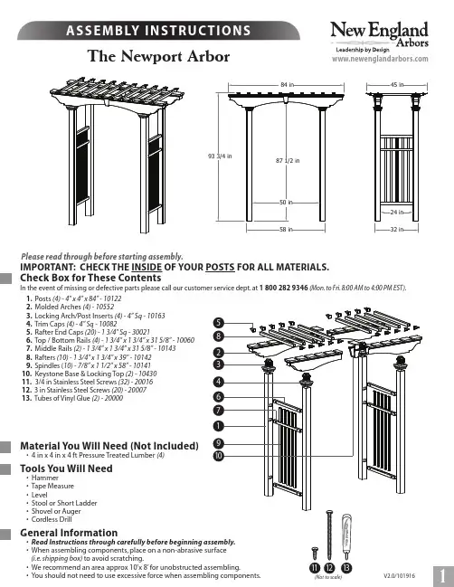
Check Box for These ContentsIn the event of missing or defective parts please call our customer service dept. at 180****9346(Mon. to Fri. 8:00 AM to 4:00 PM EST). 1. Posts (4) - 4” x 4” x 84” - 10122 2. Molded Arches (4) - 105523. Locking Arch/Post Inserts (4) - 4” Sq - 101634. Trim Caps (4) - 4” Sq - 100825. Rafter End Caps (20) - 1 3/4” Sq - 300216. Top / Bottom Rails (4) - 1 3/4” x 1 3/4” x 31 5/8” - 100607. Middle Rails (2) - 1 3/4” x 1 3/4” x 31 5/8” - 101438. Rafters (10) - 1 3/4” x 1 3/4” x 39” - 101429. Spindles (10) - 7/8” x 1 1/2” x 58” - 1014110. Keystone Base & Locking Top (2) - 10430 11. 3/4 in Stainless Steel Screws (32) - 20016 12. 3 in Stainless Steel Screws (20) - 2000713. Tubes of Vinyl Glue (2) - 20000Material You Will Need (Not Included)• 4 in x 4 in x 4 ft Pressure Treated Lumber (4)Tools You Will Need• Hammer • Tape Measure • Level• Stool or Short Ladder • Shovel or Auger • Cordless DrillGeneral Information•(i.e. shipping box) to avoid scratching.• We recommend an area approx 10’x 8’ for unobstructed assembling.• You should not need to use excessive force when assembling components.The Newport ArborPlease read through before starting assembly.1IMPORTANT: CHECK THE INSIDE OF YOUR POSTS FOR ALL MATERIALS.V2.0/101916(Not to scale)1213112Without inserting them completely, set one bottom rail and one middle rail into the holes in one of the posts as shown. Insert the spindles through the middle rail and into the bottom rail.PLEASE NOTE: All of the horizontal rails have locking tabs located at both ends. Once inserted and pushed into theholes on the posts, they will lock into place permanentlyAssemble Side Panels1Lift up the panel and slip the top rail onto the ends of the spindles. Push down ont he end of each rail until the tabs are locked into the holes in the post.Set out a second post. Flip the entire panel over and line up the rail ends with the corresponding holes in the post. As in step 2above, push the end of each rail into the holes until the locking tabs are completely inserted. Repeat steps 1through 3 for second side panel.23233The Newport ArborSlip the trim cap over the post and slide down ab out 12”. If you purchased the Trim Kit , slip the second trim cap as well as the base moldings. No Glue is required for this step.Attach Trim Pieces1If you’re using concrete to install the arbor (recommended), insert a 4 x 4 x 48” treated lumber 12” into the posts as shown.Fasten the wood insert with screws (not included).2Wood InsertNote:If you’ve purchased the Aussie Auger mounts, please refer to those instructions to complete the installation.Lay out the two arch halves. Using the glue provided , run a small bead of glue along each internal tab of the arch ends as shown.W ith the top side facing up , slip the bottom of each half together on a slight angle to join the two. Proceed to pinch in on the top tabs to allow them to slide into the arch cavity. Once the tabs are inside , push the two halves completely together.Assemble the Arches1234The Newport Arbor42Using eight of the 3/4”screws provided , fasten the arches on all four sides through the pr e-drilled holes.Take the keystone base and top and connect them over the middle of the arch as shown. Make sure the pins in the base are correctly inserted into the holes in the top. Push the two pieces together. No glue is required for this step.45Flip the arch over and slip each arch couplers into the bottom of the arch. Push firmly until they snap into place. No glue is required for this step.Repeat steps one through five for the second arch.65The Newport ArborStarting at one end , r un a 1” to 2” long bead of glue on both sides of the ‘guide pin ’ as shown.Place one of the filters and line up the hole in the filter with the guide pin. H old in place to allow the glue to bond.Repeat for the remaining filters.Assemble the Arches788Fasten the filters in place using two 3” screws per rafter as shown.Run a small bead of glue around the inside lip of the rafter end cap. Press the cap firmly onto the end of the filter and hold in place for a few seconds. Repeat this step for each end cap.Note : Allo w 10 minutes for the vinyl glue to set before lifting or moving the arch assembly.910106The Newport ArborCarry the side panels to the final location of the arbor and E x cavate four holes appro x 36 in. (91.4 cm.) dee p , 12 i n. in diameter. The spacing of the holes should be as per image aside.Carefully move the side panels into the e x cavated holes.Run a 2” - 3” long bead of glue on the ribbed flanged of the arch couplers as shown.Install The Arbor23Into Earth with Concrete FootingArbors must be well secured to prevent tipping over from wind load, etc.4Place the arch assembly over and into the side panel posts.(Y ou will need a help er).7 TollFreePhone:180********TollFreeFax:187****。
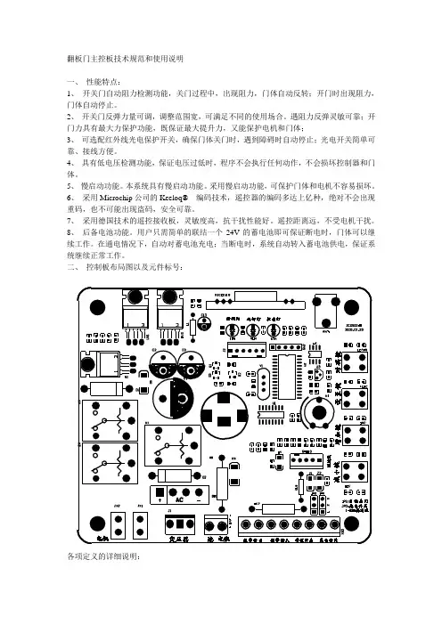
翻板门主控板技术规范和使用说明一、性能特点:1、开关门自动阻力检测功能,关门过程中,出现阻力,门体自动反转;开门时出现阻力,门体自动停止。
2、开关门反弹力量可调,调整范围宽,可满足不同的使用场合。
遇阻力反弹灵敏可靠;开门力具有最大力保护功能,既保证最大提升力,又能保护电机和门体;3、可选配红外线光电保护开关,确保门体关门时,遇到障碍时自动停止;光电开关简单可靠、接线方便。
4、具有低电压检测功能,保证电压过低时,程序不会执行任何动作,不会损坏控制器和门体。
5、慢启动功能。
本系统具有慢启动功能。
采用慢启动功能,可保护门体和电机不容易损坏。
6、采用Microchip公司的Keeloq® 编码技术,遥控器的编码多达上亿种,绝对不会出现重码,也不可能出现盗码,安全可靠。
7、采用德国技术的遥控接收板,灵敏度高,抗干扰性能好。
遥控距离远,不受电机干扰。
8、后备电池功能。
用户只需简单的联结一个24V的蓄电池即可保证断电时,门体可以继续工作。
在通电情况下,自动对蓄电池充电;当断电时,系统自动转入蓄电池供电,保证系统继续正常工作。
二、控制板布局图以及元件标号:各项定义的详细说明:1. 开关门力调整电位器W1:调整关门反弹力大小,顺时针方向为增大,逆时针方向为减小。
2. 学习灯LRN:遥控器指示灯,用于指示遥控器的工作状态。
3. 学习键LEARN:用于遥控器发射机的学习和删除。
4. 控制/报警端子:外接光电开关和手动开关控制输入/报警输入和输出接口。
从右到左依次为:光电开关接口;墙壁开关接口;报门磁警输入接口;报警门磁输出接口。
接上光电以后PB-IN输入端保持脉冲状态。
当光电开关的光线被阻断时,PB-IN输出高电平,光电开关有效;如果门机处于关门状态,则立刻反弹直到上限位。
墙壁开关:是外接控制门体开、关、停的一个外接代替遥控的开关按键。
报警门磁输入、输出是外接防盗报警的接口,报警门磁输入是外接门磁开关,报警门磁输出是外接报警器,从而实现防盗报警功能。

0 目录0 目录-------------------------------------------------------11 简介-------------------------------------------------------12 技术描述---------------------------------------------------53操作特性--------------------------------------------------164维护保养--------------------------------------------------205简单故障排除----------------------------------------------21附录------------------------------------------------------251 简介1.1 安全操作1.2 前言1.3 版权1.4 使用须知1.5 专业名词缩写1.6 选装部件1.1 安全操作美必盛自动门的设计、检验和生产是依据严格的国际标准进行的。
进行每年一次的常规维护时应确保操作程序正确(在经常使用的情况下)。
所有的工作必须由美必盛公司或美必盛公司认可的经销商来完成。
在进行操作之前必须先阅读操作手册。
警告:尽量避免接触转动部分。
如果对操作手册有任何疑问,请与宁波美必盛公司联系。
美必盛自动门地址:联系电话:网址:1.2 前言操作手册是专门为自动门的用户提供的,它向你提供如下信息:门的操作门的结构门的维护1.3 版权本操作手册是由公司提供和认可的。
它只提供给自动门的所有者和公司认可的代理商。
公司保留一切权力。
本操作手册信息的所有权归美必盛公司。
在没有得到美必盛公司的书面认可之前,将本操作手册的信息或其中的一部分泄漏给第三者是不允许的。
美必盛公司保留改进产品而不另行通知的权力。

下载文档收藏智能链条式车库门开门机安装使用说明书智能链条式车库门开门机安装使用说明书第一级设置:在待机状态下,按下“P”键约三秒钟,LED数码管闪烁显示“1”,松开按键,即进入第一设置: a.开门行程设置:LED数码管闪烁显示“OL”。
按“+”键开门,松开停止:按“—”键关门,松开停止;确定开门设置后,按“P”键确认。
如果在开门过程中自动停止,或者在关门过程中自动停止并开门,请先在第二级设置中增大开、关门负载力,然后再重新设置开门行程。
如不修改当前设置,则直接按“P”键,进入下一项设置;b.关门行程设置:LED数码光闪烁显示“CL”。
按“+”键开门,松开停止;按“—”键关门,松开停止;确定关门位置后,按“P”键确认。
如果在开门过程中自动停止,或者在关门过程中自动停止并开门,请先在第二级设置中增大开、关门负载力,然后再重新设置关门行程。
如不修改当前设置,则直接按“P”键,进入下一项设置;c.开门力量自动检测:LED数码管闪烁显示“OF”。
如果门体当前不在全关闭位置,请先按“—”键,将门体运动至全关闭位置。
按“+”键开门,LED数码管显示当前检测到的负载力数值,当门体运动至全开启位置后,完成开门力量检测,并自动进入下一项设置。
如不修改当前设置,则直接按“P”键,进入下一项设置;d.关门力量自动检测:LED数码管闪烁显示“CF”。
如果门体当前不在全开启位置,请先按“+”键,将门体运动至全开启位置。
按“—”键关门,LED数码管显示当前检测到的负载力数值,当门体运动至全关闭位置后,完成关门力量检测,并自动进入下一项设置。
如不修改当前设置,则直接按“P”键,进入下一项设置;e.发射机学习或删除:LED数码管闪烁显示“LE”。
(1)发射机学习:按“+”键,LED数码管闪烁显示“L”,发射机按键一次,LED数码光停止闪烁,再按发射机相同按件一次,LED数码管快速闪烁2秒,然后恢复闪烁显示“LE”,表示学习完成。
Cascade is a Registered Trademark of Cascade Corporationcascade ாcorporationManual Number 6019803 R-3Boxcar Door AssistPageINTRODUCTIONSpecial Definitions1OPERATOR'S GUIDESafety Rules1Boxcar Door Assist2Industrial Lift Trucks3General Setup for Opening Doors4Picking Up, Securing Unit4Opening, Closing Doors5Open Docks5Close Quarters6Disengaging and Stowing7Troubleshooting7Safe Operation and Maintenance8OSHA Regulations8INSTALLATIONTruck Requirements9Electrical Installation10INSPECTION & MAINTENANCEDaily11100-Hour Maintenance11500-Hour Maintenance111000-Hour Maintenance11SERVICEWinch Drive Assembly, Cable Replacement12Sheaves, Cable Guards, Guide Block12Electrical13PARTSProduct Identification16Base Unit16Multi-Clamp Tower Assembly18Narrow Doorway Boom/Sheave Assembly19Recommended Spare Parts back coverPublications back coverContact Cascade back coveri6019803 Rev. 36019803 Rev. 31This Section contains operating instructions for the Cascade Boxcar Door Assist. It will help you avoid common errors which can often cause damage to the equipment or personnel injury.This information is intended to simplify operator under-standing about effective and safe Boxcar Door Assist use and operation. Read this information thoroughly before operating the unit. Be sure you know andunderstand all operating procedures and safety precau-tions. If you have any questions, or don’t understand a procedure, ask your supervisor.Emphasize Safety! Most accidents are caused by operator carelessness or misjudgement. You must watch for poorly maintained equipment and hazardous situations and correct them.This User Manual is for the Cascade Boxcar Door Assist and contains an Operator's Guide, Installation Instructions,Inspection & Maintenance, Service and Parts. All specifica-tions are shown in U.S. and (Metric) units where applicable.Special DefinitionsThe statements shown appear throughout this Manual where special emphasis is required. Read all WARNINGS and CAUTIONS before proceeding with any work.Statements labeled IMPORTANT and NOTE are provided as additional information of special significance or to make the job easier.CAUTION – A statement preceded by CAUTION is information that should be acted upon to prevent machine damage.IMPORTANT – A statement preceded by IMPORTANT is information that possesses special significance .NOTE – A statement preceded by NOTE is information that is handy to know and may make the job easier.Wireless Front View - Fully Optioned Base Unit26019803 Rev. 3DA0057.illCAUTION: Electrical interlocks prevent unsafe operation with unit tilted, raised too high, or overloaded. (Faults reset automatically in 2-10 sec.)Max.6019803 Rev. 33No ridersNo reaching through mastNo standing under load46019803 Rev. 3PERATOR'S GUIDEOPick up or clamp unit and attach safety chainsAdjust forks to slot width1Position roll clamp pads on towers ABOVE fork slotsORRC1217.illDA0018.illDA0019.ill2General setup for opening boxcar doorsPicking up, securing unitDA0002.illWARNING – Remain in truck or stay clear of No Stand Zone when opening or closing boxcar door.Assure cable is rigged parallel to door and floor – do not pull with cable at an angle. Cable under tension is hazardous and may result in equipment damage or bodily injury.DA0042.illNO STAND ZONE -defined by door size,movement rangeWireless Remote ControlHook, CableBoxcar Door Assist UnitCL1958.illPosition bale clamp pads on towers, pads EVEN with bottom of unitDA0023.illConnect power cable to truck or Internal Battery3ORShort Arm on RH side6019803 Rev. 3566019803 Rev. 36019803 Rev. 3786019803 Rev. 3(Specific Regulations from OSHA 1910.178 and 1917.17)(a) General Requirement(4)Modifications and additions which affect capacity and safe operationshall not be performed by the customer or user without manufactur-ers prior written approval. Capacity, operation and maintenance instruction plates, tags or decals shall be changed accordingly.(5)If the truck is equipped with front-end attachments other thanfactory installed attachments, the user shall request that the truck be marked to identify the attachments and show theappropriate weight of the truck and attachment combination at maximum elevation with load laterally centered.(6)The user shall see that all nameplates and markings are in placeand maintained in a legible condition.(e) Safety Guards(2)If the type of load presents a hazard, the user shall equip forktrucks with a vertical load backrest extension in accordance with:(a)(2) All new powered industrial trucks acquired and used by an employer after February 15, 1972 shall meet the design and construction requirements for powered industrial trucksestablished in the “American National Standard for Powered Industrial Trucks, Part II, ANSI B56.1”, except for vehicles intended primarily for earth moving or over-the-road hauling.(l) Operator TrainingOnly trained and authorized operators shall be permitted to operate a powered industrial truck. Methods shall be devised to train operators in the safe operation of powered industrial trucks.(m) Truck Operations(1)Trucks shall not be driven up to anyone standing in front of abench or other fixed object.(2)No person shall be allowed to stand or pass under the elevatedportion of any truck, whether loaded or empty.(3)Unauthorized personnel shall not be permitted to ride onpowered industrial trucks. A safe place to ride shall be provided where riding of trucks is authorized.(4)The employer shall prohibit arms or legs from being placed betweenthe uprights of the mast or outside the running lines of the truck.(5i)When a powered industrial truck is left unattended, loadengaging means shall be fully lowered, controls shall beneutralized, power shall be shut off and brakes set. Wheels shall be blocked if the truck is parked on an incline.(5ii)A powered industrial truck is unattended when the operator is 25feet or more away from the vehicle which remains in his view, or whenever the operator leaves the vehicle and it is not in his view.(5iii)When the operator of an industrial truck is dismounted andwithin 25 feet of the truck still in his view, the load engaging means shall be fully lowered, controls neutralized and the brakes set to prevent movement.(6) A safe distance shall be maintained from the edge of ramps orplatforms while on any elevated dock or platform or freight car.Trucks shall not be used for opening or closing freight doors.(10) A load backrest extension shall be used whenever necessary tominimize the possibility of the load or part of it from falling rearward.(n) Traveling(4)The driver shall be required to slow down and sound the horn atcross isles and other locations where vision is obstructed. If the load being carried obstructs forward view, the driver shall be required to travel with the load trailing.(7i)When ascending or descending grades in excess of 10 percent,loaded trucks shall be driven with the load upgrade.(7iii)On all grades the load and load engaging means shall be tilted back ifapplicable, and raised only as far as necessary to clear the road surface.(o) Loading(1)Only stable or safely arranged loads shall be handled. Caution shall beexercised when handling off-center loads which cannot be centered.(2)Only loads within the rated capacity of the truck shall be handled.(3)The long or high (including multiple-tiered) loads which may affectcapacity shall be adjusted.(4)Trucks equipped with attachments shall be operated as partiallyloaded trucks when not handling a load.(5) A load engaging means shall be placed under the load as far aspossible; the mast shall be carefully tilted backward to stabilize the load.(6)Extreme care shall be used when tilting the load forward or backward,particularly when high tiering. Tilting forward with load engaging means elevated shall be prohibited except to pick upa load. An elevated load shall not be tilted forward except when the load is in a deposit position over a rack or stack. When stacking or tiering, only enough backward tilt to stabilize the load shall be used.(p) Operation of the Truck(1)If at any time a powered industrial truck is found to be in need ofrepair, defective, or in any way unsafe, the truck shall be taken out of service until it has been restored to safe operating condition.(q) Maintenance of Industrial Trucks(1)Any power-operated industrial truck not in safe operatingcondition shall be removed from service. All repairs shall be made by authorized personnel.(5)All parts of any such industrial truck requiring replacement shall bereplaced only by parts equivalent as to safety with those used in the original design.(6)Industrial trucks shall not be altered so that the relative positionsof the various parts are different from what they were when originally received from the manufacturer, nor shall they be altered either by the addition of extra parts not provided by the manufacturer or by the elimination of any parts. Additional counter-weighting of fork trucks shall not be done unless approved by the truck manufacturer.(7)Industrial trucks shall be examined before being placed in serviceand shall not be placed in service if the examination shows anycondition adversely affecting the safety of the vehicle. Such examina-tions shall be made at least daily. When industrial trucks are used on a round-the-clock basis, they shall be examined after each shift.Defects when found shall be immediately reported and corrected.Railroad Facilities (Ref. 1917.17)(h)Before being opened fully, doors shall be opened slightly to ensure thatthe load has not shifted during transit. Special precautions shall be taken if the doors being opened are visibly damaged.(i)If powered industrial trucks are used to open railcar doors, the trucks orthe railcar doors shall be equipped with door opening attachments.Employees shall stand clear of the railcar doors while they are being opened and closed.(j)Only railcar door openers or powered industrial trucks equipped withdoor opening attachments shall be used to open jammed doors.6019803 Rev. 39Truck RequirementsAn IC lift truck with forks or clamp attachment is required topick up the electrically powered Boxcar Door Assist Unit.Paper Roll ClampForks or Clamp Attachment•Forks (2 x 5 x 48 in. L maximum)•Paper Roll Clamp Electrical PowerTruck-Powered Unit – Requires 12V @ 200A or 24V @ 100A DC power from the truck battery or electrical system. Use the No. 2-gauge twin cable andconnectors supplied with the unit (see Page 10 for electrical cable installation).Self-Powered Unit – Contains an internal 12V battery and charger to supply all required power.No truck power connection is required.106019803 Rev. 3Truck-Powered Unit (Steps 1, 2, 4, 5) – Use the No. 2-gauge twin cable, fusebox and connectors supplied with the unit and install as shown. Connect winch power cable to truck and test unit.Self-Powered Unit (Steps 3, 4, 5) – Charge battery using 12V charger supplied. Connect winch power cable to internal battery••secure cable.•Mount fuesbox solidly to truck if possible, or secure with cable ties to prevent movement.Determine location on truck cowl for power connectorcable to truck, or to unit internal battery6019803 Rev. 311DailyCheck items shown each day. Report problems to your supervisor.100-HourComplete the following inspection and maintenance on the Boxcar Door Assist Unit:•Check safety chains, hooks and chain anchors for damage. Replace damaged or missing parts.•Check for loose or missing fasteners. Tighten or replace if necessary.•Check cable sheaves and cable guards for freedom and proper operation. Replace damaged or worn parts.•Check electrical power cable, battery (if equipped)and connectors for damage. Replace damaged or worn parts •Check winch cable/hook by pulling out to full length and assuring there are no frayed or broken strands or kinks in the cable. Replace cable if it does not meet the above inspection criteria.500-Hour•Replace winch cable.1000-Hour•Replace cable sheevesRemote•Connect battery charger to power cable and charge battery for 8 hours.126019803 Rev. 31.0Winch Drive AssemblyThere are no field-servicable items on the winch drive assembly except for the cable/wire rope.1.11side-to-side.2sheaves to the IMPORTANT:3into the slot. 4IMPORTANT: DA0066.ill2.0Blockdescribed below:1new parts as shown.23430 ft.-lbs. (40 Nm).6019803 Rev. 3133.0Electrical3.1Main Power Fuse1Locate Boxcar Door Assist fusebox, which is near truck battery on truck-powered unit or near battery hold-down on self-powered unit.2Remove the cover and replace the fuse as shown.Assure that the stud terminals are reassembled as shown.CAUTION: Assure that the replacement fuse is the correct ampere rating for the winch:12V system – 200 Amp (Part No. 6017353)3.2Power Cable HarnessesCAUTION:Boxcar Door Assist Unit1contactor. CAUTION:damage.2capscrews.3other cables and wires as shown. correct polarity Truckharness on the truck.Power Cable Capscrews,WashersContactor Cover146019803 Rev. 33.3Winch Contactor, Motor Power CablesCAUTION: Before working on the contactor and winch cables, disconnect the power cable.1Remove the cover from the contactor.CAUTION: Covers contain electrical components and wiring – handle carefully to avoid damage.2Disconnect the main power cable harness from the + and – terminals on the winch contactor. Forreassembly, the main power cable is installed on top of the other cables and exits along the RH side(driver’s view) of the contactor (see illustration below).3Disconnect the remaining cables and wire harnesses from the contactor. Remove the contactor from the frame. For reassembly, tighten the contactor cap-screws to 5 ft.-lbs. (8 Nm).4For reassembly, reverse the above procedures with the following exceptions:•Install a new winch contactor.CAUTION: Assure all cables and wires arereconnected properly and with correct polarity .Serious damage may result with the cablesmisconnected. Refer to illustrations and schemat-ics for correct hookup.DA0072.illWINCH POWER CABLE SCHEMATICcontactor are swapped: F1 is connected to F2, and F2 is connected to F1.Electrical power from truck or internal battery.Winch Motor Power CablesCurrent Sensor IMPORTANT: Arrow must point toward negative connection to motor.3.4Circuit Board Controller,Wiring HarnessesCIRCUIT BOARD WIRING HARNESS SCHEMATICCurrent Winch Cover166019803 Rev. 36014809 Rev. 317REF QTY PART NO.DESCRIPTION6024568Base Unit – 12V 6024569Base Unit – 24V 116015241Winch – 12V 6022171Winch – 24V216025812Cable Assembly ▲316020248Knob ▲446001Square Nut, .37554629516Capscrew, .375 x 1.00616024660Spring Tensioner 716019902Platform Weldment 88768538Capscrew, M10 x 3094209043Washer, M10104767614Capscrew, M10 x 201123550Capscrew, .25 x .3751216020238Winch Cover136206321Capscrew, M6 x 16146202346Washer, M61516020229Bumper, Rubber 166202348Washer, M12176768556Capscrew, M12 x 451866020689Bushing 1916020233Brake Pad 204787383Washer, M102112787381Nut, M102226016660Sheave ◆234683162Shim ◆2426020106Pin ◆252682999Eye Pin ◆262787398Washer, M8◆272767961Capscrew, M8 x 16◆2816021248Fairlead Weldment ◆2926021751Safety Chain Assembly 3026021355Safety Chain Assembly3116019453Power Wire Assembly, Base Unit3216019450Power Wire Assembly/Fuseblock, Truck 338206322Washer, M103416021112Controller Assembly 3516021110Cover ■3616024410Circuit Board ■3716025862Wire Harness3816024807Emergency Release Pushbutton 3916026851Current Sensor 4016036925Winch Contactor ▲4126389Lockwasher, .254216021752Guard4316028481Cable Wedge Anchor ●4416026661Remote Transmitter▲Included with Winch.◆Included in Center Sheave Assembly 6021908.■Included with Controller Assembly 6021112.● Included with Cable Assembly 6025812. Reference:SK-7152.15A186014809 Rev. 3TowerREF QTY PART NO.DESCRIPTION6021945Tower Assembly 116020171Tower Weldment 26215419Washer, M2036679082Capscrew, M20 x 35426020627Whip Spring 54787398Washer, M862686119Lockwasher, M872767414Nut, M882765352Capscrew, M8 x 30926020249Rubber Pad1024783608Capscrew, M10 x 161126020224Bar6014809 Rev. 319cBoxcar Door AssistUNITS SERVICED PART NUMBERDESCRIPTION1-56-1920-506016660Sheave w/Bearing 2246021668Cable Guide Block 1246021811Cable/Hook Assembly 1246028481Cable Wedge Anchor 1246026661Wireless Remote1116019450Truck Power Harness/Fuseblock 1116017353200A Fuse (12V)123ECR2032Wireless Remote Battery123Users – Cascade product literature, service literature, parts and videos are available through authorized lift truckdealers. To find the dealer nearest you, contact:Lift Truck Dealers – To order parts, service literature or videos:Boxcar Door AssistPART NO.DESCRIPTION6019803User Manual (Operation, Installation, Service, Parts)679929Tool Catalog673964Literature Index Order Form 6024073Promotional CDContacting CascadeCascade Parts Sales 2501 Sheridan Ave.Springfield, OH 45505Tel: 888-CASCADE (227-2233)FAX: 888-329-0234Recommended Spare Parts© Cascade Corporation 200511-2005Part Number 6019803 R-3North America/South America Cascade CorporationU.S. Headquarters 2201 NE 201stFairview, OR 97024-9718Tel: 800-CASCADE (227-2233)503-669-6300Fax: 888-329-8207EuropeCascade N.V.European Headquarters P,O, Box 30091300 El Almere Damsluisweg 561332 ED Almere The Netherlands Tel: 31-36-5492911Fax: 31-36-5492964。
双雄车库门开门机调试及功能介绍使用本产品前请仔细阅读使用保养说明,以保证您安全,正确,高效地使用双雄牌自动遥控上滑门。
使用注意事项自动遥控上滑门是一种机电设施,在开门机电机推拉力及扭簧的平衡扭力作用下门体上下运动,如不正确操作可能会造成较为严重的伤害事故,为了您和他人的安全,请根据下述内容正确操作车库门。
1、自动遥控上滑门须由专业技术人员按严格的程序进行安装,用户不可自行安装,否则安装不善可能对您或他人造成严重伤害或门体损坏。
2、手动操作时,用手拉动离合器拉绳使离合器脱开,然后用手将门体上移,打开车库门。
手动操作为应急装置,非必要时尽量使用电动开启,以免产生不必要的故障。
3、开启,关闭上滑门时操作人员不得离开现场,门下严禁站人或行走,以确保安全。
4、应将遥控器放置在儿童触及不到的地方,否则可能发生危险。
5、明确车库门完全关闭后方可离开。
6、车库门不论在电动或手动开关时,切记不能将手放在两块门板的连接处,否则可能导致手的严重受伤。
7、严禁擅自拆装替换任何部件,以免发生危险,一旦出现异常情况,请及时与厂商联系,由专业人员处理。
功能特点杭州双雄机电技术有限公司专业生产各种自动遥控车库门和自动遥控车位器。
双雄自动上滑车库门集电气、机械、控制为一体。
是二十一世纪实现家居智能化,办公智能化的理想车库门系统。
双雄自动上滑车库门体采用彩涂钢板/聚氨酯发泡材料/彩涂钢板结构,整体造型美观大方,门板坚固耐用,绝缘隔热。
集装饰,防护功能于一体。
通过双雄开门机驱动上滑门的开启与关闭,运转平稳,超低噪音。
上、下行程智能按键调整,定位精确可靠。
遥控器滚码调频,防止解码。
设有障碍检测装置,开闭安全。
停电时,可手动操作,方便省力。
结构图(图一)技术参数电源电压:…………220V 50HZ 交流公称拉力:…………600N运行速度:…………每秒17厘米运行距离:…………可调至5米耗电量(运行中): 140W 公称扭矩:…………12N.m耗电量(待机状态):4W 门体材料:……… 钢/聚氨酯发泡/钢操作方法:......... 遥控、手动遥控距离: (20)门支撑杆:………可变长度门臂手动装置:………电机离合装置人身安全:………遇障碍物反弹电机类型:………直流减速电机附件均使用低电压电机工作电压:…24V 直流升降力:…………数码式独立调整行程设置:………数码式独立调整使用保养方法一、遥控操作双雄牌上滑门为您配有遥控装置,您可使用遥控器开门与关门。
车库门发展到现在主要分为遥控、感应、电动、手动几种,而车库门遥控器[1]即为远程控制车库门启闭的装置。
一般来讲,车库门遥控器通常采用遥控器中的无线电遥控器,而非红外遥控器,因为与家电常用的红外遥控器相比,无线电遥控器拥有以下的优点,无线电遥控器是用无线电波来传送控制信号的,它的特点是无方向性、可以不“面对面”控制、距离远(可达数十米,甚至数公里)、容易受电磁干扰。
在需要远距离穿透或者无方向性控制领域,比如车库门遥控控制、工业控制等等,使用无线电遥控器较易解决。
下面对无线遥控器做一个简单的介绍:无线遥控器(RF Remote Control)是利用无线电信号对远方的各种机构进行控制的遥控设备。
这些信号被远方的接收设备接收后,可以指令或驱动其它各种相应的机械或者电子设备,去完成各种操作,如闭合电路、移动手柄、开动电机,之后再由这些机械进行需要的操作。
作为一种与红外遥控器相补充的遥控器种类,在车库门、电动门、道闸遥控控制,防盗报警器,工业控制以及无线智能家居领域得到了广泛的应用。
常用的无线电遥控系统一般分发射和接收两个部分。
发射部分一般分为两种类型,即遥控器与发射模块,遥控器和遥控模块是对于使用方式来说的,遥控器可以当一个整机来独立使用,对外引出线有接线桩头;而遥控模块在电路中当一个元件来使用,根据其引脚定义进行应用,使用遥控模块的优势在于可以和应用电路天衣无缝的连接、体积小、价格低、物尽其用,但使用者必须真正懂得电路原理,否则还是用遥控器来的方便。
接收部分一般来说也分为两种类型,即超外差与超再生接收方式,超再生解调电路也称超再生检波电路,它实际上是工作在间歇振荡状态下的再生检波电路。
超外差式解调电路与超外差收音机相同,它是设置一本机振荡电路产生振荡信号,与接收到的载频信号混频后,得到中频(一般为465kHz)信号,经中频放大和检波,解调出数据信号。
由于载频频率是固定的,所以其电路要比收音机简单一些。
1 目录1、目录 (1)2、安装所需工具 (2)3、技术参数 (2)4、性能特点 (3)5、安全注意事项 (5)6、门体安装指导 (6)6²1、门体安装 (6)6²2、导轨安装 (6)6²3、平衡系统安装 (13)6²4、安装与调试 (19)7、驱动装置的安装指导 (18)6²1、驱动装置装配 (18)6²2、驱动装置吊装 (19)6²3、电源插座安装与布线 (22)8、遥控及负载能力的调节 (22)8²1、遥控器的调整及使用 (22)8²2、负载力的调节 (23)8²3、遇障碍反应特性测试 (24)9、附件安装指导 (24)9²1、墙壁按钮的安装 (24)9²2、电眼安装 (25)10、行程调节 (27)11、常见故障及处理方法 (27)3、技术参数电源:AC220V 50Hz功率:100W电机电压:DC24V电机转速:43±3rpm工作电流:0.7A开门速度:150mm/sec噪音:≤65dB4、性能特点4²1、百信车库门驱动装置是我公司自行开发的先进新型驱动装置,它是整体式设计,不仅可有效保证稳定可靠运行,安装也较简便且适于超低空安装。
超静运行——遥控车库门的各项设计都遵循降低噪音使运行安静平稳的原则。
如采用低压直流电机,克服了交流电机的噪音和抖动现象,采用高精度和高表面光洁度铝型材导轨、轻质高强度链条等都保证驱动器的超静音及运行平稳可靠;自动控制——采用数字控制技术代替了模拟控制技术,使得控制系统抗干扰能力增强、可靠性提高。
使用加密的遥控器可使您安全、轻松、全天候地进行控制;自动保护——设计充分考虑安全保护,因而您不必担心人身安全问题。
关门行程遇障碍物时门自动反向运行,开门行程遇障碍物时门自动停止。
假如您不经意忘记了关门,那么我们专门设计的控制系统会帮您在设定的时间内自动关门(客户有要求时添加此功能);可靠自锁——利用电机自锁原理使门体无论是在全关闭状态、全开启状态还是中间的任何位置均能自动可靠锁紧;照明系统——为方便您的出入,门一旦运行,按常规设计照明灯自动亮并延时三分钟。
目录 (1)功能简述: (2)1. 产品介绍 (3)1.1门禁系统基本组成部分 (3)1.2产品分类 (3)1.3门禁软件特征 (3)1.4特色功能 (3)1.5丰富的输入输出控制功能 (3)1.6多种控制模式 (4)1.7优越的远程控制功能 (4)1.8联动控制功能 (4)1.9报警事件 (4)1.10系统安全性 (5)1.11电子地图 (5)1.12适用场合 (5)2. 硬件参数 (5)3. 门禁控制器接线 (6)3.1 TCP/IP 通讯方式门禁控制器接线示意图 (6)3.2 RS485通讯方式门禁控制器接线示意图 (7)3.3接线示意图补充说明 (7)4. 门禁控制器联网示意图 (9)4.1 485通讯控制器联网示意图 (9)4.2 TCP/IP通讯控制器联网示意图 (9)5. 工程规图 (11)6. 布线要求 (11)7. 安装注意事项 (11)8. 门禁系统的使用 (12)8.1安装设置流程图 (12)8.2具体安装步骤及说明 (12)8.3扩展部分设置 (15)9. 常见问题 (15)附录一: (16)非接触式感应卡读卡器 (16)附录二:..................................................................................... 封面3门禁与DVS联动拍照.......................................................................... 封面3欢迎您选用我公司门禁机,为了您正确、方便、快捷地使用本产品,同时更详细的了解本产品的功能,请您在使用本产品前认真阅读此说明书。
功能简述:外观设计时尚优美,设备可与墙面设计装潢完美结合,更符合实际用户的需求。
真正网络版门禁,整套系统只需安装一个数据库,管理端无须安装数据库。
按星期、按任意天数和按月排列的时段规律,彻底解决人员轮班,三班倒等问题。
车库门电机说明书篇一:各种车库门电机配遥控各种车库门电机,开门机配置遥控器方法一、施普雷特:对[5P] + —P000按下“P”键约3秒钟,LED数码管闪烁显示“1”,松开按键。
点按“P”键4—5下,当出现LE时去按“+”键,会出现“L”时,对码进行学习。
用遥控器红色键,快速点按4下。
(先双击2下,再双击2下)对码后,等待再次出现“5P”时,遥控可用。
切记:在操作中显示屏不可乱按“+”“—”键,不然,车库门将不能使用二、门人:后盖打开后,线路板内有:“遥控键”,“对码键”直接按下学习。
三、霍斯:按外边的“S”键进行学习。
四、莱特:电机后面或灯罩内有一个按键。
按一下进行学习。
五、佳禾:K1K2K3K4O O O O(按K1键或K4键,其他键不动。
)六、玛斯特:电机后有一个红色按键,按一下进行学习。
七、老施普雷特:电机侧面打开有一按键,按一下进行学习。
八、理想,巨光,驰豹,森玛,昌顺,新奥诺:学习都是用电机里的学习按键进行学习。
九、美国力马:早期电机后面有一个大的绿色按键,将其按下,进行学习。
(按新遥控器两下)现在电机后面有一个红色的按键,将其按下,进行学习。
(按新遥控器两下)十、索玛学习方式:按“P”键四次指示灯7闪亮,然后按“+”指示灯7常亮。
这时按要匹配的遥控器任意键两秒指示灯7闪亮,按“P”键保存,其它灯常亮,匹配成功。
要删除在用的遥控器,即指示灯7闪亮后,按“-”3秒,指示灯7由常亮变为闪亮,所有遥控删除,再按“P”键保存模式并退出。
按P两下,遥控器4下,但是遥控器必须是同类。
十一、中天800N(博达的一样):长按P键约5-6秒,直至7号灯闪亮(此状况下可以进行对码、消码操作)1、消码:按”-“号键3秒钟左右,7号灯由闪亮到熄灭,松开按键后,待7号灯再闪亮,消码成功。
2、对码:7号灯闪亮时,按”+“号键一下,7号灯由闪亮变为常亮,再按遥控器操作键一下,7号灯由常亮变为闪亮,按P键保存,对码成功。
完整word版,门禁系统使用说明书编辑整理:尊敬的读者朋友们:这里是精品文档编辑中心,本文档内容是由我和我的同事精心编辑整理后发布的,发布之前我们对文中内容进行仔细校对,但是难免会有疏漏的地方,但是任然希望(完整word版,门禁系统使用说明书)的内容能够给您的工作和学习带来便利。
同时也真诚的希望收到您的建议和反馈,这将是我们进步的源泉,前进的动力。
本文可编辑可修改,如果觉得对您有帮助请收藏以便随时查阅,最后祝您生活愉快业绩进步,以下为完整word版,门禁系统使用说明书的全部内容。
目录一系统概述 (01)二系统操作 (04)三系统编程 (09)四系统配置及选材 (19)五系统原理图 (21)六系统连线示意图 (25)七安装调试 (29)八系统各部件的安装说明 (31)九其它事项 (31)备注:本手册中所提及的终端设备(门口机、分机、管理机、围墙机),除特别说明外,主要是以可视系统AB-6A—402的设备为主。
一、系统概述AB—6A-402楼宇对讲系统是采用单片机微电脑控制技术,数位总线传输技术而设计的小区联网可视对讲系统。
系统数据传输距离可达5000米(需加中继器),防雷抗干扰,可实现大型小区的系统联网。
AB—6A—401楼宇对讲系统是非可视系统,除无视频外,其余性能与AB—6A-402系统相同。
两种系统主要适用于高楼大厦房型.整个系统由门口主机(带联网功能)、室内分机、信号隔离器、主机电源、管理中心、管理中心电源、多门选择器、围墙机、信号中继器以及联网信号切换器等设备构成。
(见下表)◇编码门口主机AB—402D长×宽×厚(mm)外形尺寸:316×136×56开孔尺寸:280×114×34◇可视室内分机长×宽×厚(mm)外形尺寸:220×205×65(AB—402M)235×188×50(AB—402MQ)◇信号隔离器(AB-402A,AB-402B)长×宽×厚(mm)外形尺寸:85×85×37◇主机电源/隔离器电源/管理中心电源(UPS-DP/UPS—P/UPS-CP)长×宽×厚(mm)外形尺寸:190×180×73◇管理中心(AB-602C)长×宽×厚(mm)外形尺寸:240×267×65二、系统操作(一)门口机(402D)与用户分机通话1。