W3100G-EC无线数传快速安装指南-V1.1-2014.12.16
- 格式:pdf
- 大小:1.54 MB
- 文档页数:2

智能环保数采仪说明书2015年5月版本变更说明版本号编写时间说明编写人审核人VerV1.02015/04/30E智能环保数采仪初版冯立刚蔡红娇VerV1.12015/05/261、模拟量设置界面增加“高级配置”2、数字量接入的因子设置界面添加“因子扩展”冯立刚蔡红娇目录版本变更说明 (1)前言 (6)第1章概述 (9)1.1产品简介 (9)1.2产品特点 (9)第2章产品技术参数 (11)2.1主控单元技术指标 (11)2.2数传单元技术指标 (12)2.3维护单元技术指标 (12)2.4工作环境指标 (13)第3章产品外观 (14)3.1产品结构组成 (14)3.2主控单元 (15)3.2.1主控单元前面板接口 (15)3.2.2主控单元后面板接口 (16)3.2.3指示灯说明 (17)3.3无线数传单元 (18)3.3.1系列一:W3100G-EC-HB/M (18)3.3.2系列二:W3100G-EC-HB (20)3.4维护单元(选配) (21)3.4.1接口说明 (21)3.4.2指示灯说明 (22)3.4.3SIM卡安装说明 (22)第4章产品安装说明 (23)第5章设置说明 (24)5.1设置前准备 (24)5.2主控单元设置 (25)5.2.2设置软件登录 (26)5.2.3常规设置 (26)5.2.4模拟量设置 (28)5.2.5串口协议设置 (30)5.2.6网络参数配置 (32)5.2.7烟气参数配置 (35)5.3数传单元设置 (36)5.4维护单元设置(选配) (38)5.5写入设备 (39)第6章测试说明 (40)6.1测试准备 (40)6.2测试方法 (40)6.3测试结果分析 (41)第7章主控单元升级 (43)7.1升级原则 (43)7.2升级软件组成介绍 (43)7.3升级前准备 (44)7.4升级过程 (44)7.4.1打开软件 (44)7.4.2升级完成 (45)第8章显示屏操作说明 (47)8.1数据一览 (47)8.2历史查询 (48)8.2.1数据查询 (48)8.2.2数据补传 (49)8.3在线诊断 (50)8.3.1断电记录 (51)8.3.2IO检测 (52)8.3.3版本信息 (52)8.3.5程序自检 (53)8.3.6数据导出 (53)8.3.7通讯日志 (54)8.3.8SN信息 (54)8.4在线状态 (55)8.5趋势分析 (56)8.6系统设置 (57)8.6.1常规参数设置 (59)8.6.2模拟量设置 (59)8.6.3串口设置 (61)8.6.4因子上报设置 (64)8.6.5网络参数 (65)8.6.6时间校准 (69)8.6.7密码设置 (70)8.6.8烟气参数 (70)8.6.9校准屏幕 (71)8.6.10RMU设置(选配) (71)8.6.11键盘 (72)8.6.12保存配置 (73)8.7关于我们 (73)第9章产品行业应用 (74)9.1典型应用 (74)第10章FAQ (75)10.1数采仪频繁重启问题 (75)10.2模拟量数据显示异常的问题 (76)10.3串口协议数据解析异常问题 (79)10.4屏幕无响应问题 (80)10.5数采仪无法升级问题 (80)10.6平台收不到数据问题 (81)第11章安全规范 (83)11.1保护设备 (83)11.2安全运输 (83)11.3安全开箱 (83)第12章维护保养说明 (84)第13章售后服务 (85)前言尊敬的用户:欢迎您使用我司为您提供的环保数采仪产品及使用说明书。
无线数据通信产品EIC-CC12 CDMA无线数传(DTU)使用说明书 V5.0北京东方讯科技发展有限公司© 版权所有 2011北京东方讯科技发展有限公司 重要提示:版权 产品专利号:ZL 2007 2 0149247.5此文档的版权属于北京东方讯科技发展有限公司,任何个人和单位未经北京东方讯科技发展有限公司的许可,不得随意进行复制、传播、修改和引用,违者将受到法律的制裁。
英文缩写对照表APN 接入点名称 Access Point NameAPP 应用业务 ApplicationBG 边际网关 Border GatewayBGP 边际网关协议 Border Gateway ProtocolBSC 基站控制器 Base Station ControllerBSS 基站系统 Base Station SystemBSSGP 基站系统GPRS协议 BSS GPRS ProtocolBTS 基站收发系统Base Transceiver SystemCDR 呼叫详细记录 Call Detail RecordCGF 计费网关功能 Charging Gateway FunctionCSD 电路交换数据 Circuit Switch DataDDN 数字数据网 Digital Data NetworkDHCP 动态主机配置协议 Dynamic Host Configuration ProtocolDNS 域名系统 Domain Name SystemDSC 数据业务中心 Data Service CenterDTU 数据终端单元 Data Terminal UnitEGP 外部网关协议 External/Exterior Gateway ProtocolEIGRP 外部Internet组路由协议 External/Exterior Internet Group RoutingProtoco lEMC 电磁兼容 Electro Magnetic CompatibilityESP 静电防护 Electro Static PrecautionsETSI 欧洲电信标准协会 European Telecommunications Standards Institute GGSN GPRS支持节点网关 Gateway GPRS Support NodeGMSC 移动交换中心网关 Gateway MSCGPRS 通用分组无线业务 General Packet Radio ServiceGSM 全球移动通信系统 Global System for Mobile CommunicationsGSN GPRS支持节点 GPRS Support NodeGTP GPRS隧道协议 GPRS Tunneling ProtocolGTP‐id GTP标识 GTP IdentityHLR 注册地信息注册器 Home Location RegisterHSCSD 高速电路交换数据 High Speed Circuit Switch DataIGMP 互联网组管理协议 Internet Group Management Protocol IGRP 互联网网关路由协议 Internet Gateway Routing Protocol IN 智能网 Intelligent NetworkIP 互联网协议 Internet ProtocolISDN 综合数字业务网络 Integrated Services Digital Network ISP 互联网业务提供商 Internet Service ProviderL2TP 第二层隧道协议 Layer 2 Tunneling ProtocolLA 位置区域 Location AreaLLC 逻辑链路控制 Logical Link ControlMAP 移动应用部分 Mobile Application PartMDNS 移动域名系统 Mobile Domain Name SystemMDTU 移动数据终端单元 Mobile Data Terminal UnitMIB 管理信息库 Management Information BaseMS 移动台 Mobile StationMSC 移动交换中心 Mobile Switching CenterMT 移动终端 Mobile TerminalMTBF 平均故障时间 Mean Time Between FailureMTTR 平均维护时间 Mean Time To RecoveryN/A 不可用 Not ApplicableNAS 网络接入服务器 Network Access ServerNAT 网络地址转换 Network Address TranslationNTP 网络时间协议 Network Time ProtocolO&M 运行和维护 Operations & MaintenancePAP 密码授权协议 Password Authentication ProtocolPDP 分组数据协议 Packet Data ProtocolPDN 分组数据网络 Packet Data NetworkPLMN 公众陆地移动网络 Public Land Mobile NetworkPOS 销售终端 Point of SalesPTM‐G 点对多点群呼 Point‐to‐Multipoint Group CallPTM‐M 点对多点多播 Point‐to‐Multipoint MulticastQoS 服务质量 Quality of ServiceRA 路由范围 Routing AreaRADIUS 远程授权拨入用户服务 Remote Authentication Dial In User Service RIP 路由信息协议 Routing Information ProtocolRSC 注册业务中心 Register Service CenterRTOS 实时操作系统 Real Time Operating SystemRTP 实时传输协议 Real‐time Transport ProtocolRTU 远方终端单元 Remote Terminal UnitRSVP 资源预留协议 Resource reSerVation ProtocolSCADA 监控与数据采集系统 Supervisory Control and Data Acquisition SGSN GPRS服务支持节点 Serving GPRS Support NodeSIM 用户标识模块 Subscriber Identify ModuleSMS 短消息业务 Short Message ServiceSMSC 短消息服务中心 Short Message Service CenterSNMP 简单网络管理协议 Simple Network Management ProtocolSTK SIM卡工具包 SIM Tool KitsTCP 传输控制协议 Transmission Control ProtocolTDMA 时分多址 Time Division Multiple AccessTMN 电信管理网络 Telecommunication Managed NetworkUDP 用户自带寻址信息协议 User Datagram ProtocolUIM 用户标识模块 User Identify ModuleUMTS 通用移动电信系统 Universal Mobile Telecommunication System USSD 非结构化补充业务数据 Unstructured Supplementary Service Data UTK UIM卡工具包 UIM Tool KitsVLR 访问地注册器 Visitor Location RegisterWAN 广域网 Wide Area NetworkWAP 无线应用协议 Wireless Application ProtocolWDDN 无线DDN Wireless Digital Data Network目 录第一章产品简介 (7)1.1 产品特征 (7)1.2 原理框图 (9)1.3 系统组成 (9)1.3.1 硬件 (9)1.3.2 串口信号 (9)1.3.3 串口通讯参数 (10)1.3.4 软件系统 (10)1.4 技术规格 (10)1.5 技术参数 (11)1.5.1 电源 (11)1.5.2 指示灯 (11)1.5.3 接口定义 (11)1.5.4 拨码开关 (12)1.5.5 天线接口 (12)第二章安装 (12)2.1 开箱 (12)2.2 设备安装与电缆连接 (13)2.2.1 安装UIM卡 (13)2.2.2 安装天线 (13)2.2.3 安装串口 (13)2.3 检测网络情况 (14)第三章参数配置与测试 (14)3.1 DTU终端配置 (Configurations) (14)3.2 DTU参数配置工具使用 (15)3.3 通讯测试 (20)3.3.1 测试前准备工作 (20)3.3.2 通讯测试 (21)第四章常见问题 (27)4.1 面板指示灯的定义 (27)4.2 DTU终端使用说明 (28)4.3 参数设置的问题 (28)4.4 不能进行正常通信: (28)4.5 拨打电话检查设备状态 (29)第五章附录 AT指令集 (29)5.1 +TSQ询问所有参数 (29)5.2 +BAUD波特率 (29)5.3 +COM串口参数 (30)5.4 +BUF串口缓冲区大小 (30)5.5 +TIME串口超时时间 (31)5.6 +LIP本地IP地址 (31)5.7 +LP本地端口 (31)5.8 +RIP远程IP地址 (32)5.9 +RP远程端口 (32)5.10 +DNAME域名 (32)5.11 +DC域名更新周期 (33)5.12 +DNS域名服务器DNS (33)5.13 +PT协议类型 (33)5.14 +ID设备标识 (34)5.15 +CC网络状态的检测周期 (34)5.16 +APN GPRS APN设置 (34)5.17 +NUM拨号号码 (35)5.18 +UN用户名 (35)5.19 +PW密码 (35)5.20 +AUTH认证方式 (36)5.21 +CB控制字节 (36)5.22 +RT重启时间 (36)5.23 +MT模块类型 (37)5.24 +HT心跳时间 (37)5.25 +VER版本号 (38)5.26 +SAVE保存当前所有参数的修改 (38)5.27 混合方式设置参数举例 (38)第一章 产品简介本章概要的介绍EIC-CC12 CDMA无线数传(DTU)的构成、特点与工作原理等:1.产品特征2.主要功能3.系统组成4.技术规格5.外部接口EIC-CC12 CDMA无线数传(DTU)是以CDMA网络为通信平台,提供标准的RS-232/485/TTL接口,按照工业标准设计,可直接与RTU、PLC、智能仪表、单片机控制器等各种工业现场的下位机设备连接。
GPRS 无线数据传输模块 (DATA-61CD 系列用户安装使用说明内容提要请用户根据内容提要选读说明书。
GPRS 无线数据传输模块使用说明书共 13部分。
下面将介绍各部分章节主要内容。
第 1~3部分为公共部分,主要介绍产品功能、技术参数、安装接线, 以及各项注意事项等,请用户在安装产品前,仔细阅读。
第 4部分以通过串口设置 GPRS 无线数据传输模块的参数为例介绍了【模块设置与演示软件】的使用,以及各项参数内容的意义。
请用户在设置产品参数前,仔细阅读。
第 5~8部分介绍 GPRS 无线数据传输的组网模式及在每种组网模式下的模块设置、远程设参以及注意事项等,请用户根据组网方式进行选读。
第 5部分—————— SMS 短消息组网第 6部分—————— VPN 专网组网第 7部分——————移动专线组网第 8部分——————公网专线组网第 9部分,故障分析与排除,帮助用户判断、解决 GPRS 无线数据传输模块使用中出现的一些简单故障。
说明书正文后附有“读取 SIM 卡固定 IP 、远程设置模块参数、程序升级”的操作说明,供用户使用时参阅。
产品选型导轨式型号:DATA-6100 安装方式:导轨式、安装孔固定式外形尺寸:121mm×71.5mm×25.5mm 安装尺寸:标准 DIN-35mm 卡具安装孔距55.5mm台式型号:DATA-6101 安装方式:台式外形尺寸:124mm×99.3mm×30mm嵌入式型号:DATA-6102 安装方式:嵌入式外形尺寸:87.7mm×64mm×16mm 安装尺寸:67mm×32mm目录一产品简介 ........................................................................................................................................... . (1)二技术参数 ........................................................................................................................................... . (3)三产品安装说明 ..........................................................................................................................................4 3.1 产品安装尺寸 (4)3.1.1 DATA-6100安装尺寸 . ......................................................................................................... 4 3.1.2 DATA-6101安装尺寸 . (4)3.1.3 DATA-6102安装尺寸 . ......................................................................................................... 5 3.2 端子定义 (5)3.2.1 串口(DB9定义 . .............................................................................................................. 5 3.2.2 DATA-6100端子定义 . (6)3.2.3 DATA-6101端子定义 . ......................................................................................................... 6 3.2.4 DATA-6102端子定义 . ......................................................................................................... 6 3.3 产品显示说明 (6)3.3.1 LED指示灯显示说明 . ......................................................................................................... 6 3.3.2 产品工作状态说明 . ............................................................................................................ 6 3.4 正确安装与使用顺序 . .................................................................................................................... 7 3.5 安装场地选择 (7)3.5.1 安装场地选择标准 . ............................................................................................................ 7 3.5.2 信号强度检测 . .................................................................................................................... 7 3.6 产品接线说明 (8)四模块设置软件使用说明 . (11)五短消息组网说明 (16)5.1 SMS短消息组网要求及特点 . ....................................................................................................... 16 5.2 模块设置与工作状态显示说明 . .................................................................................................. 16 六VPN专网组网说明 (20)6.1 VPN专网组网要求及特点 . ........................................................................................................... 20 6.2 模块设置与工作状态显示说明 . .. (21)七移动专线组网说明 (24)7.1 移动专线组网要求及特点 . .......................................................................................................... 24 7.2 模块设置与工作状态显示说明 . .. (25)八公网专线组网说明 (27)8.1 公网专线组网要求及特点 . .......................................................................................................... 27 8.2 模块参数设置说明 . . (28)九故障分析与排除 (30)附录 1:读取 SIM 卡固定IP . ...................................................................................................................... 31 附录 2:远程设置模块参数 ........................................................................................................................ 33 附录2.1 短消息方式设参 . ................................................................................................................. 33 附录 2.2 GPRS方式设参 . ..................................................................................................................34 附录 3:程序升级 .......................................................................................................................................37 附录 4:可选配件 .......................................................................................................................................39一产品简介1.1 概述DATA-61CD 系列产品是 GPRS/GSM无线数据传输模块,为远程设备的监测、控制,远程抄表等应用提供数据传输通道。

P/N: 180200100031B*180200100031B*TCC-100 Series Quick Installation GuideVersion 12.2, September 2021Technical Support Contact Information/support2021 Moxa Inc. All rights reserved.OverviewMany important devices used in today’s industrial environment are still designed for use with an RS-232 interface. The reason is due in part to tradition, and in part to convenience. RS-232 hardware is relatively easy to design, and the devices can be readily connected to most PCs. The drawback is that RS-232 is a point-to-point interface, and it imposes a distance limitation of only 15 meters between the device and the computer.To overcome these limitations, many users employ RS-232 to RS-422/485 converters, allowing RS-232 devices to connect to an industrial RS-422 or RS-485 network and transmit data over distances up to 1.2 km. The RS-422/485 standards overcome the distance limitation by using a differential signal for transmitting data and control signals. Transmission distance and multi-drop connections are not the only issues of importance for industrial applications. In addition, housing, wiring, power supply, and over-surge protection are also serious concerns.The TCC-100I and TCC-100I-T models come with isolation protection for users who need an industrial grade interface conversion product to extend RS-232 transmission distance and increase networking capability. The superior industrial application design, which includes DIN-rail mounting, terminal block wiring, an external terminal block power, and optical isolation for system protection, makes the TCC-100 Series suitable for use in critical industrial environments. Your RS-232 devices can be used as part of an industrial RS-422/485 network, but without any hardware or software changes.RTS/CTS RS-422 Handshaking SignalsThe TCC-100 Series supports RS-422 handshaking signals. The RTS and CTS signals help solve the RS-422 signal handshaking problem and reduce data transmission errors.Built-in RS-485 ADDC? IntelligenceADDC™ (Automatic Data Direction Control) is a Moxa technology that uses a clever hardware solution to manage RS-485’s data flow control problem. ADDC™ is a hardware data flow solution that automatically senses and controls data direction, making the handshaking signal method unnecessary.IsolationMoxa’s electrical isolation technology uses two photo couplers to create a gap in each electrical signal. One photo coupler transforms the electrical signal into a light signal, which is transmitted across a small gap, and then the other photo coupler transforms the light back into an electrical signal. In this way, the two electrical circuits are completely isolated from each other, limiting the damage that could otherwise be caused by ground loops in the electrical signal.Reverse Power ProtectionThe Reverse Power Protection feature provides extra protection against accidentally connecting the power cables to the wrong terminal. The converter is designed to automatically detect which power wire is positive and which is negative, and then adjust the power supply accordingly.DIP Switch Selectable TerminatorFor many products of this type, the termination resistor is set by a jumper located inside the product’s casing, so that the user must open the casing to disable or change the resistor’s strength. Moxa offers a better solution. The TCC-100 Series’ terminator is configured with a DIP switch located on the outside of the converter’s casing.Auto Baudrate DetectionThe TCC-100 Series incorporates a method for automatically detecting the serial signal’s baudrate by hardware. This is an extremely convenient feature for the user. Even if a device’s baudrate changes, the signal will still be transmitted through the RS-232 to RS-422/485 converter without any problem.Product Features•RS-232 to RS-422 conversion with RTC/CTS support•RS-232 to 2/4-wire RS-485 conversion•Detachable wall and DIN-rail mounting for easy RS-422/485 wiring •PWR, Tx, and Rx LEDs• 2 kV isolation (TCC-100I/TCC-100I-T) for both power and RS-422/485 signals•Operating temperature:TCC-100/100I: -20 to 60°C (-4 to 140°F)TCC-100-T/100I-T: -40 to 85°C (-40 to 185°F)Package ChecklistBefore installing the Moxa TCC-100, verify that the package contains the following items:•TCC-100/100I media converter•DK-35A: DIN-rail mounting kit•Power jack to 3-pin terminal block adaptor•User’s manual (this document)•Warranty cardNote: Please notify your sales representative if any of the above items are missing or damaged.Product Specifications Communication RS-232 SignalSupports Tx, Rx, RTS, CTS;Female DB9 interfaceRS-422/485 Signal Terminal block connector (DIP Switchselectable)4-wire RS-422 (with RTS/CTS), up to 10 nodes(1.2 km)4-wire RS-485: up to 32 nodes (1.2 km)2-wire RS-485: up to 32 nodes (1.2 km)RS-485 Data Direction ControlADDC™Baudrate 50 bps to 921.6 KbpsESD Protection 15 kVIsolation 2 kV (TCC-100I/TCC-100I-T) for both powerand signalEnvironmental LimitsOperating Temperature TCC-100/TCC-100I:-20 to 60°C (-4 to 140 °F)TCC-100-T/TCC-100I-T:-40 to 85°C (-40 to 185 °F)Storage Temperature -40 to 85°C (-40 to 185°F)Humidity 5 to 95 %RHPower RequirementsInput Power Voltage External Power 12-48 VDC, terminal block Reverse Power ProtectionProtects against V+/V- reversalOver Current ProtectionProtects against 2 signals shorted together Power Consumption TCC-100/TCC-100-T: 85 mA @ 12 VTCC-100I/TCC-100I-T: 150 mA @ 12 VPhysical CharacteristicsDimensions 67 × 100 × 22 mm (without ears)90 × 100 × 22 mm (with ears)Housing AluminumPlug-In Screw Terminal Block#22 to #16 AWGWeight 148±5 gRegulatory Approvals CE, FCC (Class A), UL-60950-1SchematicLED IndicatorsThe TCC-100’s top panel contains three LED indicators, as described in the following table: LEDNameLED Function PWRRed indicates the power is on. Green indicates the TCC-100 isreceiving data from the RS-232port.Yellow indicates the TCC-100 isreceiving data from the RS-422/485 port.Hardware InstallationInstalling the TCC-100 involves six straightforward steps:•STEP 1: Set the DIP switches •STEP 2: Attach the power supply •STEP 3: Wire the terminal block •STEP 4: Attach the RS-232 converter •STEP 5: Test the connection • STEP 6: Choose a placement optionSTEP 1: Set the DIP SwitchesThe DIP switches on the TCC100/100I are used to set the signaltransmission mode and to enable or disable the termination resistor. You can configure the converter for either RS-422 or RS-485transmission mode. Your program and serial port should be set to match the converter’s settings.SW1— Switch 1 selects RS-422 or RS-485 mode. The default is “Off”for RS-485 mode.SW2— Switch 2 selects 2-wire or 4-wire RS-485 mode. The default is“Off” for 2-wire RS-485. Note that if Switch 1 is set to RS-422mode, then Switch 2 is inactive.SW3— Switch 3 enables the terminator to 120 ohms. When enabled,the 120 ohm resistor prevents signal reflection during RS-485transmission. The default is “Off” to disable the terminator. Ifyour particular application does not require using thetermination resistor, then simply set Switch 3 to the off position to disable it. Dip Switch SettingsRS-422 (terminator active) SW1 SW2 SW3 ONON ONRS-422 SW1SW2 SW3 ONON OFF4-wire RS-485(terminator active) SW1SW2 SW3 OFFON ON4-wire RS-485 SW1SW2 SW3 OFFON OFF2-wire RS-485(terminator active) SW1SW2 SW3 OFFOFF ON2-wire RS-485 SW1SW2 SW3OFF OFF OFFThe DIP-2 switches are used to configure the pull high/low resistors for different applications.Pull High/Low ResistorDIP-2 SW1 DIP-2 SW2 150k OFF OFF 1k (default)ON ONNOTE We recommend setting the pull high/low resistor to 1k (ON/ON) when termination is enabled.STEP 2: Attach the power supplyThe TCC-100 is powered by anexternal 12 to 48 VDC power supply.To connect the power supply, runtwo wires from the V+ and V-terminals on the TCC’s 3-connectorterminal block to the DC powersupply, as shown in the figure. Oncethe power supply is connected to its power source, the PWR LED locatedon the TCC’s top panel should turnred.NOTE The TCC-100 Series supports reverse power protection. That is, it will automatically detect which power wire is negative, andwhich is positive.STEP 3: Wire the terminal blockThere are three wiring options available for connecting to the TCC-100’s RS-422/485 terminal block.2-wire RS-485When using the 2-wire RS-485 wiringoption, connect three wires from theTCC-100’s terminal block to theopposite connection. As shown in thefigure, connect from Data+ to Data+,from Data- to Data-, and from SGNDto SGND.4-wire RS-485When using the 4-wire RS-485 wiringoption, connect five wires from theTCC-100’s terminal block to theopposite connection. As shown in thefigure, connect from Tx+(B) to Rx+,from Tx-(A) to Rx-, from Rx+(B) toTx+, from Rx-(A) to Tx-, and fromSGND to SGND.RS-422When using the RS-422 wiring option,first follow the 4-wire RS-485 wiringinstructions given above.Optional RTS/CTS HandshakingSignalsIf your software is set up to send andreceive RTS/CTS signals over separatewires, you should also connect fromRTS+(B) to CTS+, from RTS-(A) toCTS-, from CTS+(B) to RTS+, andfrom CTS-(A) to RTS-.STEP 4: Attach the RS-232 connectorDepending on your application, use the appropriate serial cable to connect from the TCC-100 product’s RS-232 female DB9 port to your RS-232 device, or to your computer’s COM port. Female DB9 PINRS-2321 –2 TxD3 RxD4 –5 GND6 –7 CTS8 RTS9 – RS-232 Pin Assignment DiagramSTEP 5: Test the connectionAfter configuring the DIP switches, connecting the power, wiring the terminal block, and attaching the RS-232 connector, we suggest using a console terminal program, such as HyperTerminal or Moxa Terminal Emulator, to test the connection. If you have an RS-422/485 serial board (such as the Moxa CP-132, a 2-port RS-422/485 board) installed in your PC, you can connect your PC’s COM port to the TCC-100’s RS-232 port, and then connect the TCC-100’s RS-422/485 terminal block to one of the RS-422/485 serial board’s ports. Alternatively, if you have already set up an RS-422 or RS-485 network, you can also connect the TCC-100’s RS-422/485 terminal block directly to that network. Next, start HyperTerminal or Moxa Terminal Emulator, and then open a connection to both the COM port, and the port associated with the TCC-100’s RS-422/485 port. Test the connection by typing a few characters on your PC’s keyboard. The characters you type should show up in the HyperTerminal window that is currently inactive, indicating that the typed characters were transmitted between the TCC-100’s RS-232 port and RS-422/485 terminal block connector.STEP 6: Placement OptionsIn addition to placing the TCC-100 on a desktop or other horizontal surface, you may also use the DIN-rail or wall mount options, as illustrated below:DIN Rail Wall MountingTermination Resistor DiagramTermination is designed to mitigatenoise from the RS-422/485transmission signals. If the networkcable is too long, undesirabletransmission-line effects couldarise. The best method formitigating energy on an unusedconductor is to dissipate the energyas heat by terminating both ends ofthe unused conductor to ground with resistors (this method is called bi-directional termination). The resistance of the resistors should be equal to the characteristic impedance of the line. The most common RS-485 twisted pair has a characteristic impendence of 100 to 120 ohms. Moxa’s termination technique is bi-directional termination, which offers excellent signal integrity. With this technique, the line drivers can be located anywhere on the network.Function DiagramIsolation Block DiagramTypical ApplicationsRS-485 ApplicationA typical RS-485 application for the TCC-100 Series is shown in the following figure. In this scenario, two TCC-100 units are used to connect two PCs to an RS-485 network. The third TCC-100 is used to connect the PLC, which is designed for the RS-232 interface, to the RS-485 network. In this way, both PCs are able to interact with the PLC and the LCD display.RS-422 ApplicationA typical RS-422 application for the TCC-100 Series is shown in the following figure. In this scenario, two TCC-100 units are used to create a point-to-point connection between a PC and a scale. The advantage of using two TCC-100 units to convert from RS-232, to RS-422, and then back to RS-232, is that the RS-422 cable connecting the two converters can be up to 1.2 km in length (this is big improvement compared to the 15-m distance limitation imposed by the RS-232 interface).- 11 -。
目录第一章用户手册简介 (6)第二章产品概述 (6)2.1产品简介 (6)2.2特点 (7)2.3交换机语音 (7)第三章技术要求 (8)3.1技术要求 (8)3.1.1容量 (8)3.1.2接口类型 (8)3.1.3外设接口 (8)3.1.4 传输特性 (8)3.1.5 衰耗频率失真 (8)3.1.6 输入电平增益变化 (9)3.1.7 串音衰减 (9)3.1.8 拨号方式脉冲、音频 (9)第四章安装 (10)4.1.1 前面板 (10)4.1.2 接线面板 (10)4.2安装环境 (11)4.3硬件安装步骤 (11)4.3.1线路安装 (11)4.3.2软件安装 (12)第五章:软件使用及调试 (15)5.1软件使用 (15)5.1.1软件功能简介 (15)5.1.2 一般操作规则 (16)5.1.4权限管理 (17)5.1.5话务监控 (19)5.1.6押金管理 (19)5.1.7参数设置 (20)5.1.8费率管理 (24)5.1.9话单处理 (27)5.2.0系统 (27)第六章系统编程 (28)6.1系统编程 (28)6.1.1系统功能锁 (28)6.1.2系统初始化(系统清除) (29)6.1.3设置(修改)系统日期 (29)6.1.4分机号长设置 (29)6.1.5中继计费方式设置 (30)6.1.6入中继类型设置 (30)6.1.7中继发码方式设置 (30)6.1.8中继出局方式设置 (30)6.1.9中继出局号设置 (30)6.2.0 批处理代码 (31)6.2.1分机等级设置 (31)6.2.2分机弹性编码 (32)6.2.3话务机设置(修改) (32)6.2.4清除分机密码 (33)6.2.5 系统计费方式 (33)6.2.6 市话计费开关 (33)6.2.7 市话费率设置 (34)6.2.8市话计费延时时间设置 (34)6.2.9 市话、手机手续费和附加费设置 (34)6.3.0特服号码费率设置 (34)6.3.2 本地网(特服号)手续费及附加费设置 (35)6.3.3 国内长途费率设置 (35)6.3.4国内长途手续费和附加费设置 (35)6.3.5国际费率设置 (35)6.3.6预付款超额实时开关 (35)6.3.7国际长途手续费和附加费设置 (35)6.3.8 长途手机费率设置 (36)6.3.9 清除某分机累计话费 (36)6.4.0设置交换机门数 (36)6.4.1 设置分机闹钟服务 (36)6.4.2系统自检 (36)6.4.3 半价折率百分比设置 (36)6.4.4特殊长途手机费率设置 (37)6.4.5 分机特服权设置 (37)6.4.6 分机本地网(郊县)电话权设置 (37)6.4.7内部分机呼叫权设置 (38)6.4.8分机允许中继呼入权设置 (38)6.4.9中继开关设置 (39)6.5.0 中继呼入直拨出错处理设置 (39)6.5.1中继分组设置 (40)6.5.2分机分组中继权设置 (40)6.5.3代理总机设置 (40)6.5.4日/夜自动切换模式及等级 (40)6.5.5引导语音录制 (41)6.5.6手机费率设置 (41)6.5.7手机延时时间设置 (42)6.5.8 分机预付款设置 (42)6.5.9半价时段设置 (42)6.6.0 优惠时段设置 (43)6.6.1 特定优惠率百分比设置 (43)6.6.3分机来电显示 (43)6.6.4中继来电显示设置 (43)6.6.5设置分机呼出时限 (44)6.6.6 附加费类型 (44)6.6.7 设置账号密码及漫游操作 (44)6.6.8账号服务权限 (45)6.6.9 账号预付款 (45)6.7.0 设置账号数量 (45)6.7.1功能首位号设置 (45)6.7.2外线呼入音乐开关 (45)6.7.3 外线连选设置 (46)6.7.4农话权独立设置 (46)6.7.5市话密码限制设置 (46)6.7.6振铃二次来电显示设置 (46)6.7.7 IP字头设置 (46)6.7.8拨总机缩位 (46)6.7.9话务机循环接听 (47)6.8.0外线呼入缩位拨号功能 (47)6.8.1引导语音时长设置 (47)6.8.2内线分组设置 (47)第七章分机操作功能 (47)7.1.1呼叫内部分机 (47)7.1.2呼叫总机 (47)7.1.3呼叫外线 (48)7.1.4指定外线 (48)7.1.5来电转接 (48)7.1.6离位转移 (48)7.1.7免打扰 (48)7.1.8呼叫保护 (49)7.1.9三方通话(电话会议) (49)7.2.0代接来话 (49)7.2.1遇忙转移 (49)7.2.2遇忙回叫 (49)7.2.3密码设置 (49)7.2.4分机功能清除 (50)7.2.5分机查询外线被某分机占用 (50)7.2.6内线热线服务 (50)7.2.7外线热线服务 (50)7.2.8取消内、外线热线服务功能 (50)7.2.9中继呼入 (51)7.3.0外线转外线 (51)7.3.1外线呼叫等待功能 (51)7.3.2强插服务 (52)7.3.3总机代拨功能 (52)7.3.4分机留言功能 (52)7.3.5分机广播功能 (52)7.3.6指定代理总机 (53)7.3.7清除分机密码 (53)7.3.8自报语音服务 (53)7.3.9常见故障排除 (53)RJ45接头接线线序 (55)9A结构图 (57)第八章系统指令表 (59)第一章用户手册简介感谢您购买国威时代ws848系列商务电话交换机!本交换机是专为满足小型企业办公通信需要而设计的。
串口设备CDMA无线联网数传EIC-CC12用户手册北京东方讯科技发展有限公司目录1产品简介 (3)1.1产品特征 (3)1.2 主要功能 (3)1.3 技术规格 (3)1.4 外部接口 (4)1.4.1 电源 (4)1.4.2 指示灯 (4)1.4.3 RS232串口 (4)1.4.4 拨码开关 (5)1.4.5 天线接口 (5)2使用指南 (5)2.1配置前的准备工作 (5)2.2 EIC-CC12配置指南 (6)2.2.1 用串口工具进行配置 (6)2.2.2 用串口设置程序进行配置 (6)2.3 通讯测试 (8)3应用实例 (8)4附录:CC12 AT指令集 (8)1产品简介串口设备CDMA无线联网数传EIC-CC12是一个可以让工业用的RS232/RS485串口设备的串口通信立即转换为CDMA无线网络通信的双向转换传输设备。
转换器采用透明传输的方式,用户不用知道复杂的CDMA通讯原理和TCP/IP、UDP协议,不用更改程序即可实现原有串口设备的无线网络连接,节省您宝贵的时间和已有投资,可用于长距离通信或控制。
广泛用于楼宇自动化控制、停车场设备、交通控制、LED屏幕控制、工厂、车间、矿井、银行、电气等遥控领域。
能快速实现串口设备的遥控功能。
EIC-CC12支持RS232/RS485串口接口,直接连接串口设备使得串口设备立即具备遥控功能。
在两台串口设备之间成对使用EIC-CC12的透明传输模式,相当于延长了串口的通信距离,从而实现串口设备之间的遥控。
1.1产品特征RS232串口速率高达115200 bps串口经济型:三线标准:RXD,TXD,GND现阶段CDMA网络的建设已经成熟,CDMA数据通信具有稳数据传输定、速度快、数据量大的优点。
单程<1秒,速率>100kbps,非常适合图象传输。
支持UDP/TCP网络协议CDMA数据通信变底层的串口协议为广泛使用的TCP/IP协议掉线自动重新拨号功能通过超级终端类似于AT指令方式或设置程序灵活设置通信参数设备之间透明传输/非通明传输支持静态IP、域名、SMS找IP等多种主机发现方式供电:+5V耗电:待发射状态约120mA;发射状态约300mA;范围200mA ~480mA工作温度: -20℃~ +70℃1.2 主要功能实现RS232/RS485串口到CDMA无线网络通信的双向转换,其功能如下:把RS232/RS485串口接收到的数据转为CDMA无线网络发到控制端把CDMA无线网络接收到的控制端数据转为通过RS232/RS485串口发出1.3 技术规格接口:RS232/RS485串口、CDMA天线接口协议:TCP/UDP/IP/ICMP/PPP/PAP/DNS 电源:DC 5V尺寸:113mm ×68mm ×25mm1.4 外部接口1.4.1 电源电源规格为5V(2A)直流电源,芯为正极。
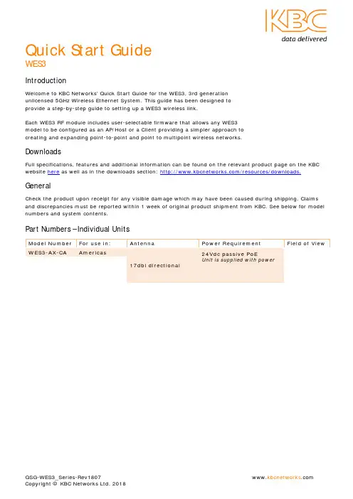
Quick Start GuideWES3IntroductionWelcome to KBC Networks’ Quick Start Guide for the WES3, 3rd generationunlicensed 5GHz Wireless Ethernet System. This guide has been designed toprovide a step-by-step guide to setting up a WES3 wireless link.Each WES3 RF module includes user-selectable firmware that allows any WES3model to be configured as an AP/Host or a Client providing a simpler approach tocreating and expanding point-to-point and point to multipoint wireless networks.DownloadsFull specifications, features and additional information can be found on the relevant product page on the KBC website here as well as in the downloads section: /resources/downloads. GeneralCheck the product upon receipt for any visible damage which may have been caused during shipping. Claims and discrepancies must be reported within 1 week of original product shipment from KBC. See below for model numbers and system contents.Part Numbers – Individual UnitsModel Number For use in: Antenna Power Requirement Field of ViewWES3-AX-CA Americas17dbi directional 24Vdc passive PoEUnit is supplied with powerQSG-WES3_Series-Rev1807 Copyright © KBC Networks Ltd. 2018WES3-KT-POE (2) WES3-AX-CF 192.168.1.200 192.168.1.201 --WES3-EDG-KT (2) WES3-AX-CA 192.168.1.200 192.168.1.201 (2) ED-G System Contents – WES3-AX-CA /-CB, -CC, -CE & WES3-AX-BA /-BB, -BC, -BE VersionsQty Description1 WES3 RF module with integrated directional antenna1 24Vdc power supply with integrated PoE injector – non PoE version only, please see table below 1 Strain-relief external RJ45 LAN port seal1 Quick Start Guide1 WES3 Pole/Wall Mounting Kit which includes:Qty Description1Pole clamp bracket1Bracket body (L/R swivel piece)2Connecting pieces (up/down alignment)250mm, 1.98” long 1/4” hex bolt2¼” hex nuts127mm, 1.06” long ¼” hex bolt2Flat washers 15mm, 0.59”2Locking washers 10mm, 0.39” long1U-bolt2¼” lock washersNote: all versions of WES3 units contain the above list of pole/wall mounting assembly kits.System Contents – WES3-AX-AA /-AB, -AC, -AE Omni-Directional VersionsQty Description1 WES3 RF module with (2) external N-connector antenna ports1 24Vdc power supply with integrated PoE injector – non PoE version only, please see table below 1Strain-relief external RJ45 LAN port seal2 5 dBi Omni-directional Antennas1 Quick Start Guide1 WES3 Pole/Wall Mounting KitSystem Contents – WES3-AX-CF /-CG & WES3-AX-BF /-BG VersionsQty Description1 WES3 PoE powered RF module with integrated directional antenna1 Strain-relief external RJ45 LAN port seal1 Quick Start Guide1 WES3 Pole/Wall Mounting KitNote: This version assumes that an IEEE802.3af PSE device is available to power the WES3 radio. No injectors or power supplies are provided.System Contents – WES3-AX-AF /-AG Omni-Directional VersionsQty Description1 WES3 PoE powered RF module with (2) external N-connector antenna ports1Strain-relief external RJ45 LAN port seal2 5 dBi Omni-directional Antennas1 Quick Start Guide1 WES3 Pole/Wall Mounting KitNote: This version assumes that an IEEE802.3af PSE device is available to power the WES3 radio. No injectors or power supplies are provided.QSG-WES3_Series-Rev1807www.kbcnetworks .comCopyright © KBC Networks Ltd. 2018Physical DeploymentThis equipment must be installed and operated in accordance with instructions found in this document. Failure to comply with these instructions will invalidate warranty.All wireless units should be programmed and bench tested install installation. KBC recommends creating a master network diagram to record all IP addresses and key network information.WES3 Factory Default Settings (unless ordered in WES3-KT or similar kits or pre-configured systems when “KBC-PRE-CONF” service was ordered)Parameter Setting LAN IP Address 192.168.1.202 GUI User Nameadmin GUI PasswordpasswordModeAccess Point (WDS)Channel/Frequency161 (5.805 GHz) Channel Spectrum Width 20/40 SSIDKBC_WES3 Pre-shared Key 11111111 MAC-Filter Disabled TX Power Output Max Antenna Gain 17Connecting to a WES3 RF ModuleKBC Networks recommends shielded, outdoor-rated, straight-through Ethernet cables when connecting near power outlets and when exposed to the elements. 24V PASSIVE POE INPUT 48V 802.3af POE INPUTWES3-AX-CA /-CB, -CC & -CE WES3-AX-CF /-CG WES3-AX-BA /-BB, -BC & -BE WES3-AX-BF /-BG WES3-AX-AA /-AB, -AC & -AE WES3-AX-AF /-AGWES3-PIM-WP: 24Vdc power supplywith integrated PoE injector POE Port WES3 RF ModuleIEEE802.3af standard PoE switch(Americas Only) Remote Power Solutions AvailableYou may also be using a KBC “Power Box” for the Client unit at the pole. In that case you would not power via the supplied injector but rather from the pass through injector built-into the “SPB” power enclosure. The following are optional power solutions which are available (Americas only) and support the WES3 series:Model Powers/ConnectsKBC-SPB-1AF-24 One <15W draw IP camera and one 24V POE input WES3 series node (eg WES3-AX-CA) KBC-SPB-1AT-24 One <30W draw IP camera and one 24V POE input WES3 series node (eg WES3-AX-CA) KBC-SPB-1AT-48 One <30W draw IP camera and one 48V POE input WES3 series node (eg WES3-AX-CF) KBC-SPB-4AF-24 Up to 4 <15W draw IP cameras and (1) 24V POE input WES3 series node (WES3-AX-CA) KBC-SPB-4AF-48 Up to 4 <15W draw IP cameras and (1) 48V POE input WES3 series node (WES3-AX-CF) KBC-SPB-24-24 (2) 24V POE WES3 series nodes (ie WES3-AX-CA) in a relay format in a location where are no cameras to connect at that specific location.KBC-SPB-48-48 (2) 48V POE WES3 series nodes (ie WES3-AX-CF) in a relay format in a location where are no cameras to connect at that specific location.KBC-SPB-4AF-48 Up to 3 <15W draw cameras (or one 30W camera) and (2) 48V POE WES3 series nodes in a wireless relay format in a location where are cameras to connect as well.KBC-SPB-HPoE-24 One <70W draw IP PTZ and one 24V POE WES3 series node (ie WES3-AX-CA)KBC-SPB-HPoE-48 One <70W draw IP PTZ and one 48V POE WES3 series node (ie WES3-AX-CF)KBC-SPB-4AF-48-70W One <70W draw IP PTZ and either two (2) 48V POE WES3 series nodes or one additional low wattage draw camera and a single 48V POE WES3 series nodeRemote power and connection to the wireless transceiver can also be made via KBC’s line of industrial battery backup UPS or solar power kits to maintain 24/7 power when onsite power is either inconsistent or unavailable. For more info see the power section of our website here. Contact KBC for info on what is needed for the correct power input.Configuring WES3 for Point-to-Point and Point to MultipointPTP = Point-to-Point / PTMP = Point to MultipointConfiguring the AP/Host Antenna1.Set laptop to static IP on 192.168.1.xxx network2.Connect to WES3 RF module as shown in previous section.3.Once WES3 RF module is connected to power source, the power LED light on the back of the unit willturn on. After 30-60 seconds you may hear the WES3 “beep”, which is normal, alerting you that it is booted up.4.Once WES3 is connected to laptop or switch the network LED on the back of the unit will turn and flashto indicate link activityOpen a web browser and type in the factory default IP address 192.168.1.202. If no response: you may be using a kit (see note in orange below) or a pre-configured system.KBC-SPB-4AF-48 or KBC-SPB-4AF-24 KBC-SPB-1AF-24 or KBC-SPB-1AT-24 /-48QSG-WES3_Series-Rev1807www.kbcnetworks .comCopyright © KBC Networks Ltd. 2018Note: factory pre-configured “kitted” WES3 units (ie WES3-KT and WES3-KT-POE) are set to 192.168.1.200 for the Host unit and 192.168.1.201 for the Client device.If using a WES3-KT, WES3-KT-P5, WES3-KT-P5T, WES3-EDG-KT or a pre-configured system using “KBC-PRE-CONF” service code, skip the following configuration steps and go to the “Instructions for Physical Deployment” at the bottom of this guide.5. Enter ‘password’ to access the Status page6. The first step is to change the LAN IP Address. Click the Network tab then click ‘Edit’7. Change the IP Address then click ‘Save & Apply’8. After the IP address is updated – it will take you back to the Login page and your browser will now be atthe new IP address. If you don’t get to the Login page make sure you don’t have an IP address conflict and ensure your laptop is set to the same network range (subnet) as the WES3.9. Now that you have logged back in – notice you are on the Status pagepassword• Highlighted are the SSID & Radio MAC Address (shown as ‘APHost MAC')• For each PTP and PTMP wireless system to connect, the APHost and client(s) need to benetworked together using the SSID and Radio MAC Address fields • KBC recommends the APHost and Client(s) share a unique SSID.• KBC also recommends the APHost be MAC locked to each client and each client should be MAClocked to its APHost• The radio MAC address can be found on the Status page (as shown above) as well as on the backof each WES3 RF module (as follows)10.11. Now in the Wireless Settings – Confirm that the SSID matches each client antenna. If you change theSSID click ‘Save & Apply’12. Click on the MAC Filter tab if this feature is desired. It is recommended for enhanced security, howevernot required for the radios to link.13. Enable the MAC-Address filter by clicking on the drop down menu to select ‘Allow listed only’ 14. Enter the radio MAC Address of each client antenna in the box15. To enter more than one radio MAC address, click the green + icon to add another field 16. When complete click ‘Save & Apply’17. If there is more than one PTP or PTMP system at one location, each APHost needs to be set to a differentunique channel or frequency. Select the channel. 18. Click ‘Save & Apply’Radio MAC Address listed here on back of every WES3 antennaQSG-WES3_Series-Rev1807 www.kbcnetworks .com Copyright © KBC Networks Ltd. 2018Configuring the Client Antenna19. Leave WES3 APHost antenna plugged in and powered up. Connect directly to the client antenna andrepeat steps 1-1120. Look at the bottom of the page under ‘Wireless Interface’ on the ‘General Setup’ tab. Look at the ‘Mode’field and select ‘Client (WDS)” from the drop-down menu.21. Verify that the SSID matches the SSID of the APHost antenna.22. Enter the radio MAC address of the AP host antenna into the “Remote MAC” field. For help see step 10.23. Click “Save & Apply”24. Now the Client and APHost are wirelessly connected. Verify wireless connection by looking at the‘Connection Status’ information.25. KBC recommends that the wireless signal strength is greater than 40 but less than 70.• Wireless Signal Strength = difference between noise & signal✓ Signal = - 36dbm ✓ Noise = - 95dbm✓ Wireless Signal Strength = 59dbm (ie, in the 40-65 range)26. You can also confirm that the wireless status bar is close to 100%27. While there is a frequency selection on the Client interface, the frequency is always driven by the APHostso no matter what channel for which the Client is selected, it will connect to its Host frequency provided that the SSID, PSK and radio MAC-filter security feature (if enabled) are all entered correctly to link wirelessly.28. The same information can be found on the Status page29.APHost in the field provided. Click on the Ping start button and confirm that you get 5 packetstransmitted and received with 0% packet loss. The average ping time should be under 10ms for most applications. Please contact KBC Networks technical support if this test fails.Connecting multiple standard WES3 Clients to a High Throughput Host/AP (ie WES3HTG series)Some systems require the use of a high throughput series ‘receiver’. The WES3 series can link to the WES3HTG provided several parameters match up. Parameter WES3 Default Setting WES3HTG Default Setting Field reconfiguration to:LAN IP192.168.1.202 192.168.1.152 Ensure that all WES3 / WES3HTG units have independent IP Addresses to avoid IP Conflicts. Record all IP changes! GUI User Name admin admin N/A GUI Password passwordpasswordN/AHost/Client ModeHost (Access Point WDS)Host (Access Point WDS)All WES3 units change to Client WDS; keep WES3HTG in Access Point WDS Mode.Channel/Freq 161 (5.805 GHz) 161 (5.805 GHz) N/A (unless a more appropriate frequency is needed in the environment)Spectrum Width 20/40 20/40/80 N/A (unless a more appropriate spectrum width is needed in the environment)SSIDKBC_WES3 WES3HTG All Clients must match Host setting; change to your desire. Record changes.Pre-shared Key11111111 11111111 No required changes, however, KBC recommends changing from default for security purposes.Remote MACN/AN/AOnly applicable to Client Mode: enter radio MAC of WES3HTG Host if this setting is desired (recommended).MAC-Filter Disabled Disabled Only applicable to Access Point Mode: enter radio MAC of each remote wireless Client unit to be connected to the Host if this setting is desired (recommended). TX Power Output MaxMaxN/AAntenna Gain17 17Change WES3HTG Host to appropriate setting depending on the model number: WES3HTG-AX-AA → 5 WES3HTG-AX-BA → 9WES3HTG-AX-CA (keep at 17)QSG-WES3_Series-Rev1807www.kbcnetworks .comCopyright © KBC Networks Ltd. 2018Instructions for Physical DeploymentThis equipment must be installed and operated in accordance with instructions found in the KBC Networks’ manual. Damage due to misuse is not covered by warranty.1. Feed the Ethernet cable through the black weather coupler protection piece prior to crimping on the RJ45connector.2. Hand-tighten the Ethernet cable connection protecting piece, do not tighten further. Damage due to over-tightening the black weather coupler into its RJ45 housing is not covered under warranty.3. The Ethernet cable should have wiggle room to allow condensation to release. Leave a gap small enoughto keep out bugs and such but open to allow moisture to release and drip down the cable away from the port.4. Do not mount the antennas horizontally or upside down. The black external LAN port should pointdownwards.5. Once the cable is inserted into the external LAN port RJ45, a small flat head screwdriver, or similar tool,is needed to release the tab of the RJ45 connector on your cable. If you pull the cable without releasing the tab, it will damage the port.Trouble-shootingContact KBC for technical assistance. Here are some ideas to try. ProblemSuggestionNo signal strength LEDsEnsure Host in Access Point WDS mode and Client(s) in Client WDS mode. Ensure that all Clients are set to matching parameters as Host. Many times when the MAC filter is enabled there is an incorrect character. Verify all characters match exactly or try disabling anderasing the “Remote MAC” from the Client side (and MAC-Filter on the Host). If they link after disabling that feature then it is likely that an incorrect MAC or character was used.Not all signal strength LEDs light upEnsure clear wide-open line of sight. If you have even just one signal strength LED then the configurations are likely correct. Try improving the alignment of the antennas and/or another frequency in case the problem is related to RF interference in the environment.Unit reboots itself continuously after a couple of minutesThe “Ping Watchdog” feature may be turned on and is configuredimproperly. Check the feature (system/tools) and disable to see if the constant auto-reboot stops.Unit stops connecting to mate antenna until a power reset is performedThis is symptomatic of 3rd party RF interference. Attempt the following suggestions:Run a scan from the Host (Network/Wireless/Spectrum) todetermine the least noisy frequency and set the Host to that channel.Reduce channel spectrum widthLower power output or try another antenna gain option Enable one of the self-healing tools such as aout-reboot byhours or ping watchdog.No Network LEDCheck all Ethernet cabling and LAN ports on all devices connected to WES3HTG unit.No access to GUI; cannot ping IP **NOTE: your system may have been pre-configured.Check provided documentation for unit IP address per serial number. If working with one of the kits, the default IP is either 192.168.1.200 or 192.168.1.201. The IP would only be 192.168.1.202 after performing a hard reset (see warning for this process below; reset as final option). It is important to record all changes. If the IP address is changed from default there is no way to recover it if forgotten other than a restore to defaults. Having to hard reset will be a time consuming effort.WES3 LED Status Indicators↑Flashing LED Solid LED LED offWSS Wireless Signal Strength (see #26)1. RSSI4/STATUS ↑In power-up / boot-up process40+ RSSIWSS less than 40 or no wireless link2. RSSI3 30-39 RSSIWSS less than 30 or no wireless link3. RSSI2 20-29 RSSIWSS less than 20 or no wireless link4. RSS1 10-19 RSSIWSS less than 10 or no wireless link5. NETWORK – Ethernet link activity - LAN Link activity established↑Link activity from wireless unit to connectedEthernet device or across wireless linkNo link to Ethernet cable connected device(not indicative of wireless link/strength)6. Power Power appliedNo power to unit.Note:The LEDs do not change color.Factory Reset to Default via GUI1.Click on ‘System’ then ‘Firmware’2.Click on ‘Perform Reset’Factory Reset to Default via Hard Reset ButtonWARNING: A hard reset to defaults will erase all saved info including the system requirements for a wireless connection. When possible, save a copy of the config file to a known and accessible location and record all changes made to the WES3 device.RESET AT USER RISK: Incorrect reset procedure can result in damage to the internal board and require a return to KBC Networks or need for replacement at user cost. If the button is pushed but not held for the duration of the reset process it MUST be powered down and retry. Do not press the button without powering down and restarting.1.Power up the WES3 RF module and allow it to go through its power up process.2.Remove the Phillips head screw near the port on the bottom of the WES3 RF module.3.Insert a small screwdriver or paperclip into screw hole in order to push the reset button.4.Hold the button for 12-15 seconds and release.5.RF module will reset to the WES3 factory default settings found on page 1 of this guide.Warranty InformationSee our website at: https:///policies-procedures/general-content/about-us/policies-procedures for warranty information covering all of KBC Networks products.ComplianceFCCChanges or modifications not expressly approved by the party responsible for compliance could void the user’s authority to operate the equipment. This device complies with Part 15 of the FCC Rules. Operation is subject to the following two conditions:•This device may not cause harmful interference, and•This device must accept any interference received, including interference that may cause undesired operation.This equipment has been tested and found to comply with the limits for a Class A digital device, pursuant to part 15 of the FCC Rules. These limits are designed to provide reasonable protection against harmful interference when the equipment is operated in a commercial environment. This equipment generates, uses, and can radiate radio frequency energy and, if not installed and used in accordance with the instruction manual, may cause harmful interference to radio communications. Operations of this equipment in a residential area is likely to cause harmful interference in which case the user will be required to correct the interference at his own expense.Industry CanadaThis Class A digital apparatus complies with Canadian ICES-003. To reduce potential radio interference to other users, the antenna type and its gain should be so chosen that the equivalent isotropically radiated power (E.I.R.P.) is not more than that permitted for successful communication. This device complies with Industry Canada license-exempt RSS standard(s).Operation is subject to the following two conditions:•This device may not cause interference, and•This device must accept any interference, including interference that may cause undesired operation of the device.Cet appareil numérique de la classe A est confrome à la norme NMB-003 Canada. Pour réduire le risqued’interférence aux autres utilisateurs, le type d’antenne et son gain doivent être choisies de façon que la puissance isotrope rayonnée équivalente (PIRE) ne dépasse pas ce qui est nécessairepour une communication réussie. Cet appareil est conforme à la norme RSS Industrie Canada exempts de licence norme(s). Son fonctionnement est soumis aux deux conditions suivantes:17 Compliance•Cet appareil ne peut pas provoquer d’interférences et•Cet appareil doit accepter toute interférence, y compris les interférences qui peuvent causer un mauvais fonctionnement du dispositif.CE MarkingCE marking on this product represents the product is in compliance with all directives that are applicable to it.This equipment may be operated in the following countries:Great Britain and Northern Ireland, Austria, Belgium, Denmark, Finland, France, Germany, Ireland, Italy, Netherlands, Norway, Portugal, Romania, Switzerland, Sweden.Installer Compliance ResponsibilityDevices must be professionally installed and it is the professional installer's responsibility to make sure the device is operated within local country regulatory requirements.RoHS/WEEE Compliance StatementEuropean Directive 2002/96/EC requires that the equipment bearing this symbol on the product and/or its packaging must not be disposed of with unsorted municipal waste. The symbol indicates that this product should be disposed of separately from regular household waste streams. It is your responsibility to dispose of this and other electric and electronic equipment via designated collection facilities appointed by the governmentQSG-WES3_Series-Rev1807 Copyright © KBC Networks Ltd. 2018or local authorities. Correct disposal and recycling will help prevent potential negative consequences to the environment and human health. For more detailed information about the disposal of your old equipment, please contact your local authorities, waste disposal service, or the shop where you purchased the product.Need Help?Please visit our website or contact your nearest KBC office or dealer.KBC Networks Office Contact InformationNorth & Latin America, USAPhone: +1 949 297 4930Toll-free: +1 888 366 4276Email: ***************************EMEA, UKPhone:+44(0)1622 618787Email: *******************************APACChinaPhone (1): +86 25 8688 3321Phone (2): +86 25 8688 4058Email: ***************************SingaporePhone: +65 98463323Email: *******************************。
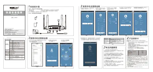
TOTOLINK 显示灯/接口/按键说明
TOTOLINK
SYS状态灯(系统状态灯)
DC IN口WAN口
LAN1/LAN2口SIM卡槽WPS/RST按键
TOTOLINK
TOTOLINK TOTOLINK
2
LR350
TOTOLINK
绿灯常亮
绿灯慢闪
绿灯快闪
橙灯慢闪
红灯常亮
红灯慢闪
设备在启动过程中或已开启WPS功能。
4G 连接成功,信号强。
设备在恢复出厂过程中。
4G 连接成功,信号一般。
检测到SIM卡但无网络。
没有插入SIM 卡或者没有检测到SIM卡。
连接电源适配器。
连接光猫或外部网络。
连接电脑或交换机。
插入SIM卡。
激活WPS功能:按下按键并持续1-3秒,直到SYS
指示灯保持常亮,路由器开始配对。
恢复出厂设置:按下按键并持续5-8秒,直到SYS
指示灯快闪。
TOTOLINK_LR350
TOTOLINK
Quectel EC200A
TOTOLINK
TOTOLINK_LR350
TOTOLINK_LR350
TOTOLINK。
CATCOM-100深入使用指南 无线数传设备 UM01010101 1.1 Date:2021/4/6©2021 Guangzhou ZHIYUAN Electronics Co., Ltd.修订历史目录1. 如何使用此文档 (1)2. 产品简介 (2)2.1 产品概述 (2)2.2 面板介绍 (2)2.2.1 指示灯 (2)2.2.2 电源 (3)2.2.3 串口 (3)2.2.4 GPIO口 (3)2.2.5 BAUD RST按键 (3)3. 设备配置 (5)3.1 配置项说明 (5)3.1.1 模块型号(DTUTYPE) (5)3.1.2 设备ID号(DTUID) (5)3.1.3 设备硬(软)件版本号(HDVER,SWVER) (5)3.1.4 设备名称(DTUNAM) (5)3.1.5 SIM卡号码(PHON) (5)3.1.6 工作模式(MODE) (5)3.1.7 数据传输模式(TRNMODE) (6)3.1.8 短信操作模式(SMSMODE) (6)3.1.9 数据中心主站数量(SVRCNT) (6)3.1.10 数据中心登录密码(SVRPWD) (6)3.1.11 数据中心服务器参数(SVRIP,SVRNAM,SVRPORT,SVRCNTMODE) (7)3.1.12 SMS传输目标号码(TRANNO4) (7)3.1.13 HTTP请求类型(HTTPTYPE) (7)3.1.14 HTTP请求方式(HTTPMETH) (8)3.1.15 HTTP请求的URL(HTTPURL) (8)3.1.16 HTTP请求超时时间(HTTPTIMEOUT) (8)3.1.17 HTTP请求头信息(HTTPHEAD) (8)3.1.18 HTTP头过滤(HTTPFILTER) (8)3.1.19 连接标准MQTT服务器的ClientID(CLIENTID) (8)3.1.20 连接标准MQTT服务器的用户名(MQTTUSR) (8)3.1.21 连接标准MQTT服务器的密码(MQTTPASS) (8)3.1.22 标准MQTT服务器的发布主题(PUBTOPIC) (8)3.1.23 标准MQTT服务器的订阅主题(SUBTOPIC) (8)3.1.24 标准MQTT服务器发布消息的QOS(QOS) (8)3.1.25 ZWS接入使能(ZWSEN) (8)3.1.26 ZWS设备类型(ZWSDEVTYPE)、设备秘钥(ZWSDEVSEC) (8)3.1.27 状态上报使能(ZWSSTAEN) (8)3.1.28 状态上报周期(ZWSSTATIM) (8)3.1.29 日志上报使能(ZWSLOGEN) (9)3.1.30 透传云本地地址(ZWSSRCADDR) (9)3.1.31 透传云目的地址(ZWSDSTADDR) (9)3.1.32 串口1波特率(SERBAUD) (9)3.1.33 串口1数据位、停止位长度(SERDAT;SERSTP) (9)3.1.34 串口1校验类型(SERCHK) (9)3.1.35 串口2波特率(SERBAUD2) (9)3.1.36 串口2数据位、停止位长度(SERDAT2;SERSTP2) (9)3.1.37 串口2校验类型(SERCHK2) (10)3.1.38 心跳包间隔时间(BEATTIM) (10)3.1.39 心跳包数据设置(BEATDATA) (10)3.1.40 注册包数据使能(REGDATA) (10)3.1.41 帧间隔时间和数据包最大长度(SERS,MTU) (10)3.1.42 空闲下线时间(IDLETIM) (10)3.1.43 APN名称(APN) (11)3.1.44 拨号号码(DIALNO) (11)3.1.45 APN访问用户名、APN访问密码(USRNAM,PWD) (11)3.1.46 授权用户号码(USERNO1、USERNO2、USERNO3) (11)3.1.47 DTU配置密码(DTUPWD) (11)3.1.48 获取信号强度(CSQ) (11)3.1.49 显示帮助信息(HELP) (11)3.1.50 复位DTU模块(RSTDTU) (11)3.1.51 重新引导系统(REBOOT) (11)3.1.52 恢复出厂设置(DEFAULT) (11)3.1.53 显示当前设置内容(SETLIST) (11)3.1.54 退出配置模式(OUTSET) (11)3.1.55 调试信息(DBGINF) (12)3.2 图形配置方式 (12)3.2.1 本地串口配置方式 (12)3.2.2 远程配置 (14)3.3 AT命令配置方式 (15)3.3.1 进入配置模式 (15)3.3.2 参数配置命令 (15)3.3.3 退出配置模式 (20)3.4 短信配置方式 (20)4. 工作模式 (23)4.1 4G透明传输模式 (23)4.2 简单命令短信息工作模式 (24)4.2.1 测试设备命令 (25)4.2.2 发送短信命令 (25)4.2.3 读取新短信 (25)4.2.4 查询设备状态命令 (26)4.2.5 设备配置命令 (26)4.2.6 重启设备命令 (27)4.2.7 命令模式下发送短信示例 (27)4.3 透明短信息工作模式 (27)4.4 HTTP工作模式 (28)4.5 MQTT工作模式 (30)4.6 透传云工作模式 (32)5. 用户命令 (35)5.1 AT+GETDTUSTATE (35)5.2 AT+CLRSNDBUF (35)5.3 AT+HTTPURL (35)5.4 AT+DSTADDR (36)6. 服务器登录注册包 (37)7. DTU流量统计方法 (38)8. 免责声明 (39)1. 如何使用此文档本文档旨在帮助用户深入学习CATCOM-100设备的使用方法。
P/N: 1802031000026 *1802031000026*UC-3100 SeriesQuick Installation GuideVersion 4.2, May 2022Technical Support Contact Information/support2022 Moxa Inc. All rights reserved.OverviewMoxa UC-3100 Series computers can be used as smart edge gateways for data pre-processing and transmission, as well as for other embedded data-acquisition applications. The UC-3100 Series includes three models, UC-3101, UC-3111 and UC-3121, each supporting different wireless options and protocols. Please refer to the datasheet for more information.Package ChecklistBefore installing the UC-3100, verify that the package contains the following items:• 1 x UC-3100 Arm-based computer• 1 x DIN-rail mounting kit (preinstalled)• 1 x Power jack• 1 x 3-pin terminal block for power• 1 x CBL-4PINDB9F-100: 4-pin pin header to DB9 female console port cable, 100 cm• 1 x Quick installation guide (printed)• 1 x Warranty cardIMPORTANT: Notify your sales representative if any of the above items are missing or damaged.Panel LayoutThe following figures show the panel layouts of the UC-3100 models: UC-3101UC-3111UC-3121LED Indicators LED Name Status FunctionNotesSYS GreenPower is onRefer to the Function Button (FN Button) and LED Indicators section in thehardware/software user manual for more details. Red FN button is pressed OffPower is offGreen (blinking)The computer is in power conservation modeLAN1/ LAN2 Green 10/100 Mbps Ethernet mode OffEthernet port is not active COM1/ COM2/ CAN1Orange Serial/CAN port istransmitting or receiving dataOff Serial/CAN port is not activeWi-FiGreenWi-Fi connection has been establishedClient mode : Three levels with signal strength1 LED is ON: Poor signal quality2 LEDs are ON: Good signal qualityAll 3 LEDs are ON: Excellent signal qualityAP mode: All 3 LEDs blinking at the same timeOff Wi-Fi interface is not activeLTEGreenCellular connection has been established Three levels based on the signalstrength1 LED is ON:Poor signal quality 2 LEDs are ON: Good signal quality All 3 LEDs are ON: Excellent signal qualityOffCellular interface is not activeInstalling the UC-3100The UC-3100 can be mounted on to a DIN rail or on to a wall. The DIN-rail mounting kit is attached by default. To order a wall-mounting kit, contact a Moxa sales representative.DIN-rail MountingTo mount the UC-3100 on to a DIN rail, do the following:1.Pull down the slider of the DIN-rail bracket located at the back ofthe unit2.Insert the top of the DIN rail into the slot just below the upperhook of the DIN-rail bracket.tch the unit firmly on to the DIN rail as shown in the illustrationsbelow.4.Once the computer is mounted properly, you will hear a click andthe slider will rebound back into place automatically.Wall Mounting (optional)The UC-3100 can also be wall mounted. The wall-mounting kit needs to be purchased separately. Refer to the datasheet for more information.1.Fasten the wall-mounting kit to the UC-3100 as shown below:e two screws to mount the UC-3100 on to a wall.These two screws are not included in the wall-mounting kit andmust be purchased separately. Refer to the detailed specifications below:Head Type: flatHead Diameter >5.2 mmLength >6 mmThread Size: M3 x 0.5 mmConnector DescriptionPower ConnectorConnect the power jack (in the package) to the UC-3100’s DC terminal block (located on the bottom panel), and then connect the poweradapter. It takes several seconds for the system to boot up. Once the system is ready, the SYS LED will light up. GroundingGrounding and wire routing help limit the effects of noise due toelectromagnetic interference (EMI). There are two ways to connect the UC-3100 grounding wire to the ground.1.Through the SG (Shielded Ground, sometimes called Protected Ground):The SG contact is the left-most contact in the 3-pin power terminal block connector when viewed from the angle shown here. When you connect to the SG contact, the noise will be routed through the PCB and the PCB copper pillar to the metal chassis.2. Through the GS (Grounding Screw):The GS is located between the console port and the power connector. When you connect to the GS wire, the noise is routed directly from the metal chassis.Ethernet PortThe 10/100 Mbps Ethernet port uses the RJ45 connector. The pin assignment of the port is shown below:PinSignal 1 Tx+ 2 Tx- 3 Rx+ 4 – 5 – 6 Rx- 7 – 8–Serial PortThe serial port uses the DB9 male connector. It can be configured by software for the RS-232, RS-422, or RS-485 mode. The pin assignment of the port is shown below:Pin RS-232 RS-422 RS-4851 DCD TxD-(A) –2 RxD TxD+(A) –3 TxD RxD+(B) Data+(B)4 DTR RxD-(A) Data-(A)5 GND GND GND6 DSR – –7 TRS –– 8 CTS – – 9 – – –CAN PortThe UC-3121 comes with a CAN port which uses the DB9 maleconnector and is compatible with the CAN 2.0A/B standard. The pin assignment of the port is shown below:Pin Signal Name1 –2 CAN_L3 CAN_GND4 –5 CAN_SHLD6 GND7 CAN_H8 – 9CAN_V+SIM Card SocketThe UC-3100 comes with two nano-SIM card sockets for cellularcommunication. The nano-SIM card sockets are located on the same side as the antenna panel. To install the cards, remove the screw and the protection cover to access the sockets, and then insert the nano-SIM cards into the sockets directly. You will hear a click when the cards are in place. The left socket is for SIM 1 and the right socket is for SIM 2. To remove the cards, push the cards in before releasing them.RF ConnectorsThe UC-3100 comes with RF connectors to the following interfaces. Wi-FiThe UC-3111 and UC-3121 models come with a built-in Wi-Fi module. You must connect the antenna to the RP-SMA connector before you can use the Wi-Fi function. The W1 and W2 connectors are interfaces to the Wi-Fi module.BluetoothThe UC-3111 and UC-3121 models come with a built-in Bluetoothmodule. You must connect the antenna to the RP-SMA connector before you can use the Bluetooth function. The W1 connector is the interface to the Bluetooth module. CellularThe UC-3100 models come with a built-in cellular module. You must connect the antenna to the SMA connector before you can use the cellular function. The C1 and C2 connectors are interfaces to thecellular module. For additional details refer to the UC-3100 datasheet. GPSThe UC-3111 and UC-3121 models come with a built-in GPS module. You must connect the antenna to the SMA connector with the GPS mark before you can use the GPS function. SD Card SocketThe UC-3111 and UC-3121 models come with a SD-card socket for storage expansion. The SD card socket is located next to the Ethernet port. To install the SD card, remove the screw and the protection cover to access the socket, and then insert the SD card into the socket. You will hear a click when the card is in place. To remove the card, push the card in before releasing it.Console PortThe console port is an RS-232 port that you can connect to with a 4-pin pin header cable (available in the package). You can use this port for debugging or firmware upgrade.Pin Signal 1 GND 2 NC 3RxD 4TxDUSBThe USB port is a type-A USB 2.0 version port, which can be connected with a USB storage device or other type-A USB compatible devices. Real-time ClockThe real-time clock is powered by a lithium battery. We stronglyrecommend that you do not replace the lithium battery without the help of a Moxa support engineer. If you need to change the battery, contact the Moxa RMA service team.Accessing the UC-3100 Using a PCYou can use a PC to access the UC-3100 by one of the following methods:A.Through the serial console port with the following settings:Baudrate = 115200 bps, Parity = None, Data bits = 8,Stop bits = 1, Flow Control = Noneing SSH over the network. Refer to the following IP addressesand login information:Default IP Address Netmask LAN 1 192.168.3.127 255.255.255.0LAN 2 192.168.4.127 255.255.255.0Login: moxaPassword: moxaATEX Specifications1.Ex nA IIC T4 Gc2.Ambient Range: -40°C ≤ Ta ≤ +70°C, or -40°C ≤ Tamb ≤ +70°C3.Rated Cable Temp ≧90 °C4.Standards Covered:EN 60079-0:2012+A11:2013EN 60079-15:20105.Hazardous Location: Class I, Division 2, Groups A, B, C, and DSpecial Conditions of Use:These devices shall be mounted in a suitable tool-accessible ATEX-certified enclosure that is rated at least IP54 as defined inEN 60529 and Pollution Degree 2 as defined in EN 60664-1, and the devices shall be used within their rated electrical andenvironmental ratings.Moxa Inc.No. 1111, Heping Rd., Bade Dist., Taoyuan City 334004, Taiwan- 11 -。
专业、专注、专心铸就一流产品专业无线DTU/RTU生产商--------万维科技W3100C无线数传使用说明书北京万维盈创科技发展有限公司(Ver3.0)目录1 前言....................................................................41.1 说明适用型号.........................................................41.2 版本说明.............................................................42 产品简介................................................................42.1 概述.................................................................42.2 主要功能.............................................................42.3 产品特征.............................................................42.4 技术规格.............................................................5设备在线情况图2.5 ......................................................52.6 设备配套说明.........................................................53 硬件说明................................................................63.1 W3100C无线数传DTU前面板说明..........................................6W3100C无线数传DTU后面板说明3.2 .........................................63.3 W3100C无线数传DTU电源说明............................................73.4 W3100C无线数传DTU功能开关说明........................................73.5天线接口..............................................................74 参数设置................................................................84.1 W3100C无线数传设备设置具备的条件.....................................84.2 W3100C无线数传参数设置前硬件安装及连接说明...........................94.3 串口设置程序进行参数设置说明.........................................95 行业应用..............................................................125.1 典型应用...........................................................126 测试流程..............................................................136.1 测试申明...........................................................136.2 测试原理...........................................................136.3 测试拓扑图.........................................................146.4 测试步骤...........................................................146.5 如何登陆路由器开放端口号(以D_Link的路由器说明)...................157 附录1 CDMA数据业务收费概况...........................................161 前言1.1 说明适用型号产品型号说明W3100C 透明CDMA传输设备1.2 版本说明版本号编写时间说明编写人审核人对以前版本的总结和升级 Zfx Jhp Ver3.0 2007.11.282 产品简介2.1 概述W3100C无线数传是基于2.5G的通信网络平台,采用透明传输的方式,给用户提供高速、永远在线、透明数据传输的虚拟专用数据通道网络。
厦门才茂2G/3G/4G无线传输终端使用手册厦门才茂通信科技有限公司厦门市软件园三期诚毅北大街63号901单元、904单元电话:传真:邮政编码:361009网址:版权所有2003-2021----才茂通信通畅天下----说明书声明版权声明:本使用说明书包含的所有内容均受版权法的保护,未经厦门才茂通信科技有限公司的书面授权,任何组织和个人不得以任何形式或手段对整个说明书和部分内容进行复制和转载,并不得以任何形式传播。
商标声明:、才茂、Caimore和其他才茂商标均为厦门才茂通信科技有限公司的商标。
本文档提及的其他所有商标或注册商标,由各自的所有人拥有。
注意:由于产品版本升级或其他原因,本文档内容会不定期进行更新。
除非另有约定,本文档仅作为使用指导,本文档中的所有陈述、信息和建议不构成任何明示或暗示的担保。
特别声明:产品说明书上的建议配置或者默认配置,不代表合适配置,客户须根据自己业务需要情况,调整成为适应自己业务开展的配置。
产品出厂的配置参数,仅供用户参考,用户收到设备时,不管有没有其他约定,用户必须全部检查一遍,并须根据自己项目和业务需求,自行调整配置好相关参数。
由于参数配置不当或者错误导致的问题,我司不承担任何责任。
同时,用户需要加强病毒攻击防范工作,因为病毒攻击导致的通信异常,我司不承担任何责任。
技术支持:地址:厦门市软件园三期B20栋901、904室网址:客服电话:************************客服传真:************客服邮箱:*******************版本说明文档版本修改说明发布日期作者签发V4.0第三次正式发布2014.05.13HuangjhV4.1修改协议参数配置说明2014.05.19Huangjh LifwV4.2修正部分错误2014.06.27LifwV4.3去掉导轨安装2014.08.07LifwV4.4更新型号列表,接口说明2014.08.08LifwV4.6修改了配置工具型号列表,修正了一些已经过期的内容2014.09.04Lixw LifwV4.7增加对3160关闭FLASH保护的功能2014.09.17Lifw LifwV4.8a、增加对50V硬件保护和重连重拨功能b、增加对3150关闭FLASH保护的功能c、修正一些通信串口参数的支持2016.07.11YangzhLianqsLianqsV4.9修正部分说明2019.06.05Liugb V5.0添加支持CAT1的型号2020.06.08Liugb V5.1修正部分说明2020.06.22Liugb V5.2公司地址变更,修正部分说明2020.09.08Liugb目录目录 (4)第一章产品简介 (7)1.1产品概述 (7)1.2产品特点 (10)1.3系统组成 (11)1.4工作原理 (11)1.5技术参数 (12)第二章安装 (14)2.1概述 (14)2.2开箱 (14)2.3安装与电缆连接 (14)2.3.1设备安装 (14)2.3.2天线及SIM卡安装 (16)2.3.3安装电缆 (16)2.4供电电源 (25)2.5检测网络情况 (25)第三章配置方式 (26)3.1本地串口配置 (26)3.1.1工具配置 (26)3.1.2手动配置 (29)3.2无线网络配置 (29)3.3短信配置(仅3180系列产品可用) (29)第四章快速配置DTU (30)第五章DTU批量配置 (32)5.1导出配置 (32)5.2导入配置 (33)第六章DTU功能详细配置 (35)6.1单中心固定IP方式的服务器信息配置 (35)6.2单中心域名方式的服务器信息配置 (36)6.3多中心固定IP方式的服务器信息配置 (37)6.4多中心域名方式服务器信息配置 (38)6.5专网(APN网络)配置 (40)6.6DTU标识配置 (41)6.6.1设备ID号配置 (41)6.6.2设备SIM号配置 (42)6.7工作串口参数配置 (42)6.7.1串口波特率配置 (42)6.7.2串口校验位配置 (43)6.7.3串口数据位配置 (43)6.7.4串口停止位配置 (43)6.7.5串口流控制配置 (43)6.8唤醒功能配置 (44)6.8.2电话唤醒配置 (45)6.8.3数据唤醒配置 (45)6.9通信协议配置 (46)6.9.2注册包配置 (50)6.9.3心跳包配置 (51)6.9.4注册回应包配置(仅3180系列和3181系列产品可用) (51)6.9.5心跳回应包配置(仅3180系列和3181系列产品可用) (51)6.8.4混合唤醒配置 (52)6.8.5IO唤醒配置(仅3180系列产品可用) (52)6.10工作模式配置 (52)6.11心跳包发送间隔时间配置 (53)6.12设备重连配置 (53)6.12.1设备重连次数配置 (54)6.12.2设备重连间隔时间配置 (54)6.12.3多中心重连间隔时间配置 (54)6.12.4设备重拨次数配置 (55)6.13数据包封包配置 (55)6.13.1全速发送配置(只适用于xx80系列) (56)6.14调试等级配置 (56)6.15本地端口配置(仅3180系列产品可用) (57)6.16远程短信配置功能配置(仅3180系列产品可用) (58)6.16.1短信中心号码配置 (59)6.16.2远程短信控制手机 (59)6.17IO输出输入配置(仅3180EP产品可用) (59)6.17.1短信中心号码配置 (60)6.17.2IO输出功能配置 (61)6.17.3IO输入功能配置 (61)6.17.4IO输入/输出功能说明 (62)6.18短信数据通道设置 (62)6.18.1数据通道短信功能配置 (63)6.18.2通道启用配置 (63)6.18.3发送成功提示配置 (64)6.18.4发送失败提示配置 (64)6.18.5收发数据手机号配置 (65)6.19服务器模式参数配置 (65)6.19.1xx50服务器模式参数配置(仅CMxx50(P_EP)(SERVER)可用) (66)6.19.2xx60服务器模式参数配置 (67)第七章数据传输和网络远程配置试验 (68)7.1试验网络结构 (68)7.2DTU参数配置 (68)7.3服务器端配置 (69)7.3.1配置服务器内网IP (69)7.3.2端口映射 (71)7.3.3数据中心软件配置 (72)7.4DTU连接中心 (72)7.5数据接收和发送 (72)7.5.2DTU向数据中心发送数据 (73)7.6远程配置DTU (73)第八章拨号上网 (74)附件一:运营商网络参数信息 (85)附件二:AT命令集 (86)附件三:指示灯的说明 (88)附件四:设备功耗 (88)附件五:超级终端配置 (88)附件六:常见故障分析 (91)附件七:TCP协议文档 (92)附件八:UDP协议文档 (93)第一章产品简介1.1产品概述CAIMORE DTU(Data Transfer Unit,全称数据传输单元,本文简称DTU)为用户提供高速、永远在线、TCP/UDP 透明数据传输的工业级无线终端设备。