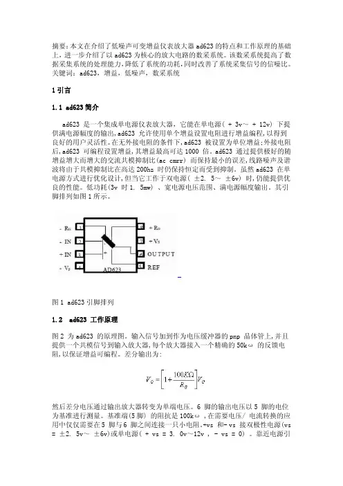
AD5426资料
- 格式:pdf
- 大小:1.31 MB
- 文档页数:32
Dual 8-,10-,12-Bit High Bandwidth
Multiplying DACs with Serial Interface AD5429/AD5439/AD5449
Rev. 0 Information furnished by Analog Devices is believed to be accurate and reliable. However, no responsibility is assumed by Analog Devices for its use, nor for any infringements of patents or other rights of third parties that may result from its use. Specifications subject to change without notice. No license is granted by implication or otherwise under any patent or patent rights of Analog Devices. Trademarks and registered trademarks are the property of their respective owners. One Technology Way, P.O. Box 9106, Norwood, MA 02062-9106, U.S.A. Tel: 781.329.4700 www.analog.com Fax: 781.326.8703© 2004 Analog Devices, Inc. All rights reserved. FEATURES
10 MHz multiplying bandwidth
50 MHz serial interface
2.5 V to 5.5 V supply operation
±10 V reference input
Pin compatible 8-, 10-, and 12-bit DACs
Extended temperature range: −40°C to +125°C
16-lead TSSOP package
Guaranteed monotonic
Power-on reset
Daisy-chain mode
Readback function
0.5 µA typical current consumption
APPLICATIONS
Portable battery-powered applications
Waveform generators
Analog processing
Instrumentation applications
Programmable amplifiers and attenuators
Digitally controlled calibration
Programmable filters and oscillators
Composite video
Ultrasound
Gain, offset, and voltage trimming FUNCTIONAL BLOCK DIAGRAM
SYNCAD5429/AD5439/AD5449
VREFBVREFA
SCLKSDIN
IOUT1BIOUT1A8-/10-/12-BITR-2R DAC A
8-/10-/12-BITR-2R DAC BRFBA
POWER-ONRESETDACREGISTER
DACREGISTER
RFBRRFBR
IOUT2A
IOUT2B
LDAC04464-0-001VDD
CLR
RFBBINPUTREGISTER
INPUTREGISTERSHIFTREGISTER
LDACSDO
Figure 1.
GENERAL DESCRIPTION
The AD5429/AD5439/AD54491 are CMOS 8-, 10-, and 12-bit
dual-channel current output digital-to-analog converters,
respectively. These devices operate from a 2.5 V to 5.5 V power
supply, making them suited to battery-powered and other
applications.
The applied external reference input voltage (VREF) determines
the full-scale output current. An integrated feedback resistor
(RFB) provides temperature tracking and full-scale voltage
output when combined with an external current-to-voltage
precision amplifier.
These DACs utilize a double-buffered, 3-wire serial interface
that is compatible with SPI®, QSPI™, MICROWIRE™, and most
DSP interface standards. In addition, a serial data out pin (SDO)
allows daisy-chaining when multiple packages are used. Data
readback allows the user to read the contents of the DAC
register via the SDO pin. On power-up, the internal shift
register and latches are filled with zeros and the DAC outputs
are at zero scale.
As a result of manufacture on a CMOS submicron process,
these parts offer excellent 4-quadrant multiplication character-
istics, with large signal multiplying bandwidths of 10 MHz.
The AD5429/AD5439/AD5449 DAC are available in 16-lead
TSSOP packages.
1 US Patent Number 5,689,257.
元器件交易网www.cecb2b.comAD5429/AD5439/AD5449
Rev. 0 | Page 2 of 32 TABLE OF CONTENTS
Specifications.....................................................................................3
Timing Characteristics.....................................................................5
Absolute Maximum Ratings............................................................7
ESD Caution..................................................................................7
Pin Configuration and Function Descriptions.............................8
Terminology......................................................................................9
Typical Performance Characteristics...........................................10
General Description.......................................................................15
Unipolar Mode............................................................................15
Bipolar Operation.......................................................................16
Stability........................................................................................16
Single-Supply Applications........................................................17
Positive Output Voltage.............................................................17 Adding Gain................................................................................18
Divider or Programmable Gain Element................................18
Reference Selection....................................................................19
Amplifier Selection....................................................................19
Serial Interface................................................................................20
Microprocessor Interfacing.......................................................22