温控阀zwt-20
- 格式:pdf
- 大小:902.71 KB
- 文档页数:37

Close-off pressures are variable and actuator dependent, consult Select Pro and/or Price Guide for specifics.ApplicationThese valves are designed to meet the needs of HVAC and commercial applications requiring bubble tight shut-off for liquids. Typical applications include chiller isolation, cooling tower isolation, change-over systems, large air handler coil control, bypass and process control applications. The large Cv values provide for an economical control valve solution for larger flow applications. Designed for use in Victaulic® piping systems.Jobsite NoteValve assembly should be stored in a weather protected area prior toinstallation. Reference the butterfly valve installation instruction for additional information.2*AFAB C DEF17.0” [433]3.8” [97]17.8” [451]15.5” [394]2.3” [58]F680VIC Technical Data SheetPressure Enhanced Rubber SeatD a t e c r e a t e d , 02/27/2020 - S u b j e c t t o c h a n g e . © B e l i m o A i r c o n t r o l s (U S A ), I n c .GKAB C DEF11.3” [286]3.8” [97]12.8” [325]10.5” [267]2.3” [58]GR N4AB C DEF14.1” [358]3.8” [97]14.1” [358]11.7” [298]2.3” [58]Dimensions (Inches [mm])GMA B C DEF9.9” [251]3.8” [97]12.8” [325]10.5” [267]2.3” [58]Dimensions (Inches [mm])AB C DEF11.7” [298]3.8” [97]14.5” [368]12.1” [307]2.3” [58]F680VIC Technical Data SheetPressure Enhanced Rubber SeatD a t e c r e a t e d , 02/27/2020 - S u b j e c t t o c h a n g e . © B e l i m o A i r c o n t r o l s (U S A ), I n c .GRAB C D EF10.8” [275]3.8” [97]10.7” [273]8.4” [214]2.3” [58]F680VIC Technical Data SheetPressure Enhanced Rubber SeatD a t e c r e a t e d , 02/27/2020 - S u b j e c t t o c h a n g e . © B e l i m o A i r c o n t r o l s (U S A ), I n c .*Variable when configured with MFT options.†Rated Impulse Voltage 800V, Type of action 1.AA, Control Pollution Degree 32*AFX24-MFT-X1 Technical Data SheetModulating, Spring Return, 24 V, Multi-Function Technology®D a t e c r e a t e d , 04/03/2020 - S u b j e c t t o c h a n g e . © B e l i m o A i r c o n t r o l s (U S A ), I n c .Wiring Diagrams!WARNING! LIVE ELECTRICAL COMPONENTS!During installation, testing, servicing and troubleshooting of this product, it may be necessary to work with live electrical components. Have a qualified licensed electrician or other individual who has been properly trained in handling live electrical components perform these tasks. Failure to follow all electrical safety precautions when exposed to live electrical components could result in death or serious injury.AActuators with appliance cables are numbered.Meets cULus requirements without the need of an electrical groundconnection.Provide overload protection and disconnect as required.Actuators may also be powered by 24 VDC.Only connect common to negative (-) leg of control circuits.A 500 Ω resistor (ZG-R01) converts the 4 to 20 mA control signal to 2to 10 VDC.Control signal may be pulsed from either the Hot (Source) or Common(Sink) 24 VAC line.For triac sink the Common connection from the actuator must be connected to the Hot connection of the controller. Position feedback cannot be used with a triac sink controller; the actuator internalcommon reference is not compatible.IN4004 or IN4007 diode. (IN4007 supplied, Belimo part number 40155).46Actuators may be controlled in parallel. Current draw and input impedance must be observed.47Master-Slave wiring required for piggy-back applications. Feedback from Master to control input(s) of Slave(s).2*AFX24-MFT-X1 Technical Data SheetModulating, Spring Return, 24 V, Multi-Function Technology®D a t e c r e a t e d , 04/03/2020 - S u b j e c t t o c h a n g e . © B e l i m o A i r c o n t r o l s (U S A ), I n c .2*AFX24-MFT-X1 Technical Data SheetModulating, Spring Return, 24 V, Multi-Function Technology®D a t e c r e a t e d , 04/03/2020 - S u b j e c t t o c h a n g e . © B e l i m o A i r c o n t r o l s (U S A ), I n c .。

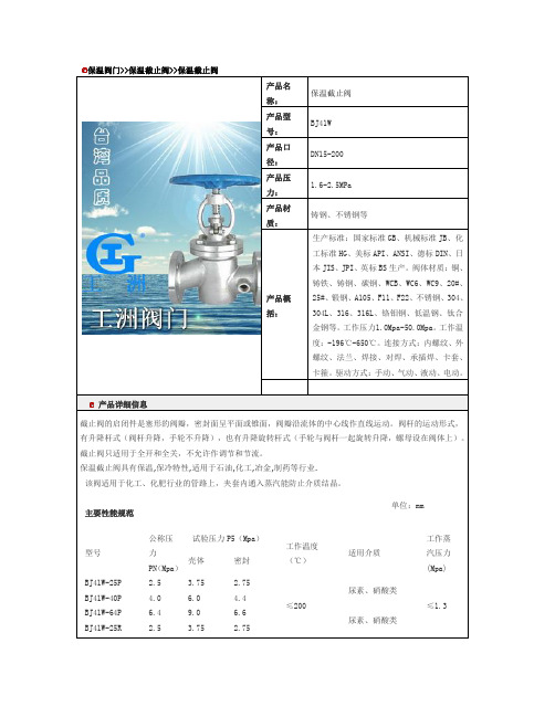
保温阀门>>保温截止阀>>保温截止阀产品名称:保温截止阀产品型号:BJ41W产品口径:DN15-200产品压力:1.6-2.5MPa产品材质:铸钢、不锈钢等产品概括:生产标准:国家标准GB、机械标准JB、化工标准HG、美标API、ANSI、德标DIN、日本JIS、JPI、英标BS生产。
阀体材质:铜、铸铁、铸钢、碳钢、WCB、WC6、WC9、20#、25#、锻钢、A105、F11、F22、不锈钢、304、304L、316、316L、铬钼钢、低温钢、钛合金钢等。
工作压力1.0Mpa-50.0Mpa。
工作温度:-196℃-650℃。
连接方式:内螺纹、外螺纹、法兰、焊接、对焊、承插焊、卡套、卡箍。
驱动方式:手动、气动、液动、电动。
产品详细信息截止阀的启闭件是塞形的阀瓣,密封面呈平面或锥面,阀瓣沿流体的中心线作直线运动。
阀杆的运动形式,有升降杆式(阀杆升降,手轮不升降),也有升降旋转杆式(手轮与阀杆一起旋转升降,螺母设在阀体上)。
截止阀只适用于全开和全关,不允许作调节和节流。
保温截止阀具有保温,保冷特性,适用于石油,化工,冶金,制药等行业.该阀适用于化工、化肥行业的管路上,夹套内通入蒸汽能防止介质结晶。
主要性能规范单位:mm型号公称压力PN(Mpa)试验压力P5(Mpa)工作温度(℃)适用介质工作蒸汽压力(Mpa) 壳体密封BJ41W-25P 2.5 3.75 2.75≤200尿素、硝酸类≤1.3BJ41W-40P 4.0 6.0 4.4BJ41W-64P 6.4 9.0 6.6尿素、硝酸类BJ41W-25R 2.5 3.75 2.75BJ41W-40R 4.0 6.0 4.4 BJ41W-64R 6.49.06.6主要尺寸公称压力 PN (Mpa )公称通径 DN (mm )尺 寸(mm )L D D1 D2 D3 B1 F0 B D6 3-G Z-φd H H1D 0 2.5 4.01517010675 55 35 8 4 16 51 3/8 4-φ14250262 120 2019011585 65 42 8 4 16 58 3/8 4-φ14292308 140 2521013510078 50 8 4 18 66 3/8 4-φ18340375 160 3223014511085 60 8 4 18 76 1/2 4-φ18338375 160 2.5 4.04026016012510072 8 4 20 88 1/2 4-φ18360386 160 5030018014512094 8 4 221101/2 8-φ18410450 240 65340195160135105 8 4 221211/2 8-φ18440485 240 80380230190160128 11 4.5 241501/2 8-φ18540600 280 100430270220188154 11 4.5 281761/2 8-φ18560625 320 125490300250218182 11 4.5 302041/2 8-φ18625737 36150 553328248212 11 4.5 32 1/212-φ257279036。

1.∙254°C〜-IOIc为“超低温阀门”适用于“超低温阀门”(-254°C(液氢)〜-10ΓC(乙烯))主体材料必须选用面心立方晶格的奥氏体不锈钢、铜合金或铝合金,其热处理后的低温力学性能,特别是低温冲击韧性必须达到标准的要求。
下列奥氏体不锈钢可用于作超低温阀门。
ASTMA351CF8M、CF3M、CF8、CF3;ASTMA182F316 、F316L> F304、F304L;ASTMA433 316、316L、304、304L;以及兰州高压阀门厂自行设计、制定的低温钢CF8D(兰州高压阀门厂工厂标准:GFQ81-93)o超低温阀门的阀体、阀盖、闸板或阀瓣等在精加工前,必须在液氮(-196°C)中进行深冷处理。
2.-100o C--30C为“低温阀门”适用于低温阀门(-100°C~-30°C)的主体材料有低温奥氏体不锈钢和低温承压件用铁素体和马氏体钢。
低温用奥氏体不锈钢有ASTMA351CF8M、CF3M、CF8、CF3,ASTMA182 F316、F316L>F304、F304L,ASTMA433 316>316L>304>304L和CF8D0以上奥氏体不锈钢也适宜工作温度为-IoO°C~-30°Co低温承压件用铁素体和马氏体钢有ASTMA352LCA(-32℃);LCB、LCC(-46℃);LCl(-59°C);LC2、LC2.1(-73℃);LC3(-100°C)oASTMA352标准中的材料,虽然材料的初级价格较低,但是其冶炼时化学成分必须有可靠且要求十分严格的工厂内控标准。
其热处理工艺复杂,需要多次作调质处。
低温冲击韧性达不到标准要求时,不允许投料作低温钢使用。
把在-29°C~200°C的这一温度区域工作的阀门,我们称其为“常温阀门:其主要理由是:这一温度区域是制造阀门的主要材料基本上都适宜的温度;而且它是耐腐蚀不锈钢在酸液介质中的耐腐蚀工作温度的上限,例如:CF8,CF3;304,304L在硝酸类介质中工作温度W200℃;CF8M,CF3M;316,316L在醋酸类介质中工作温度W200°C;200℃是用聚四氟乙烯作阀门的密封元件(如:密封阀座,密封垫片,填料等)的最高温度值;200℃是硅橡胶(SI),氟橡胶(EPM)的最高工作温度;还有在“临氢”工况中工作的阀门,在200℃以下氢分子离解为氢原子的量可以忽略不计等等。

温控阀安全操作及保养规程温控阀是一种用于进行温度控制的设备,在不同的场景中都有广泛的应用。
为了保证温控阀的正常使用效果,并保障操作人员的安全,我们需要遵循一些操作规程和保养方法。
本文将为大家介绍温控阀的安全操作及保养规程。
在操作之前,请务必仔细阅读本文并按照规程操作,以免造成损失或危险。
一、温控阀的安装及使用1. 安装1.温控阀应该安装在干燥、通风良好的场所。
2.温控阀的安装要求与使用场所的温度、压力、流量相匹配。
3.温控阀的安装要预留操作和维护所需的空间。
4.温控阀的安装需要进行承压测试和泄漏测试,测试合格方可投入使用。
5.温控阀的安装应由专业技术人员进行,确保安装正确。
2. 使用1.在使用前,应仔细熟悉该温控阀的结构、性能和规格,并按照说明书正确操作。
2.在使用温控阀时,应避免出现异常操作和非正常状态,以免造成损失或危险。
3.温控阀的使用需定期进行维护及保养,维护时间间隔视使用频率和环境而定。
4.使用温控阀时,应避免过度过热、过压及过流,以避免损坏温控阀并造成危险。
3. 停用1.在温控阀停用前,需将温度调节器调至最低温度,并切断供电。
2.在长时间停用或更换温控阀时,需将管道内的介质全部清理干净,并密封好接口。
二、温控阀的保养1. 定期清洗温控阀内部存在传动装置等机械部件,易受介质侵蚀,因此需要定期清洗以确保机械部件的正常运转。
清洗过程中,需要注意以下几点:1.清洗过程需要拆卸温控阀,慎重操作。
2.清洗完毕后,应仔细检查机械部件的运转状况,确保其正常。
3.完成清洗后,需要重新安装温控阀,确保安装正确。
2. 定期检查定期检查温控阀的工作状态和机械部件的状况,及时发现并解决存在的问题。
检查的内容主要包括:1.温度调节器的调节情况,需按照使用规程合理调节。
2.温度传感器的位置是否正确,以免造成温度误差。
3.温控阀机械部件运转状况是否正常,缺乏润滑等情况需及时解决。
3. 润滑保养温控阀的机械部件需要进行润滑保养,以确保其正常运转。

自力式温控阀(铸钢)SLZW型的详细说明SLZW型自力式温度调节阀不需外界能源而进行温度自动调节。
它适用于蒸汽、热水、热油等为介质的各种换热工况。
广泛应用于供暖、空调、生活热水中的温度自动调节,以及特殊工况的温度自动调节,如化工、纺织、制药等生产工程。
济南工达生产的-自力式温控阀一、工作原理:自力式温度调节阀利用液体受热膨胀及液体不可压缩的原理实现自动调节。
温度传感器内的液体膨胀是均匀的,其控制作用为比例调节。
被控介质温度变化时,传感器内的感温液体体积随着膨胀或收缩。
被控介质温度高于设定值时,感温液体膨胀,推动阀芯向下关闭阀门,减少热媒的流量;被控介质的温度低于设定值时,感温液体收缩,复位弹簧推动阀芯开启,增加热媒的流量。
二、使用特点:1. 安装简单。
2.无需电源气源。
3.调节设定简易。
4.平衡阀芯设计自力式压差控制阀不需外来能源,依靠被调介质自身压力变化进行自动调节,自动消除管网的剩余压头及压力波动引起的流量偏差,恒定用户进出口压差,有助于稳定系统运行,自力式压差控制阀特别适用分户计量或自动控制系统中。
自力式压差控制阀不需外来能源,依靠被调介质自身压力变化进行自动调节,自动消除管网的剩余压头及压力波动引起的流量偏差,恒定用户进出口压差,有助于稳定系统运行,自力式压差控制阀特别适用分户计量或自动控制系统中。
自力式压差控制阀的性能特点:自力式压差控制阀为双瓣结构,阀杆不平衡力小,结构紧凑,用于供热(空调)水系列中,恒定被控制系统的压差,并有以下的特点:1、恒定被控制系统压差;2、支持被控系统内部自主调节;3、吸收外网压差波动;4、采用先进的无级调压结构,控制压差可调比可达25:1;5、具备自动消除堵塞功能;6、法兰尺寸符合GB4216.2中灰铸铁法兰尺寸。
自力式压差控制阀的技术参数:1、公称压力:1.6MPa;2、介质温度:0-150℃;3、工作压差范围:0.02-0.3MPa;4、控制压差设定值:0.02MPa;控制压差可调范围0.02-0.3MPa;5、导压管长度:1.6m;6、导压管连接端尺寸:1/2"管螺纹;自力式压差控制阀的选型说明:按式KV=G/式中(G-M3/h),根据最大流量和可能的最小工作压差计算所需的最大KV值,应小于阀门的最大KV值;根据最小流量和可能的最大工作压差计算所需的最小KV值,应大于阀门的最小KV值,如G=3-10M3/h,△P"最大=200KPa,△P"最小=20KPa,KV最大=10/=25,KV 最小=3/=2.12,选择DN50即符合要求,建议尽量不变径选用阀门。
B220VS•Bronze Body, Stainless Steel Ball and StemType overviewType DNB220VS20 Technical dataFunctional data Valve size [mm]0.75" [20]Fluid chilled or hot water, up to 60% glycol, steamFluid Temp Range (water)-22...280°F [-30...138°C]Body Pressure Rating600 psig WOG psiClose-off pressure ∆ps600 psiFlow characteristic modified equal percentageMax Differential Pressure (Steam)35 psiFlow Pattern2-wayLeakage rate ANSI Class VIControllable flow range90° rotationCv51Maximum Inlet Pressure (Steam)35 psi [241 kPa]Maximum Velocity15 FPSMaterials Valve body Bronze B584-C84400Housing seal PTFESpindle316 stainless steelSpindle seal RPTFESeat RPTFELock nut stainless steelPipe connection NPT female endsRetainer B16 BrassBall316 stainless steelSuitable actuators Non-Spring NMB(X)GRCB(X)GRB(X)Spring NFSafety notesWARNING: This product can expose you to lead which is known to the State of California tocause cancer and reproductive harm. For more information go to B220VSApplicationProduct featuresThis valve is typically used in air handling units on heating or cooling coils, and fan coil unit heating or cooling coils. Some other common applications include Unit Ventilators, VAV Box re-heat coils and bypass loops. This valve is suitable for use in a hydronic system with variable flow.This valve is designed with MFT functionally which facilitates the use of various control input.Up to 35 psi steam1/2" - 2" 600 PSIG WOG, Cold Non-Shock Federal Specification: WW-V-35C, Type II Composition: BZ Style: 3Flow/Mounting detailsDimensionsType DN B220VS20B220VS+GRC..N4AB CD E F 14.1" [358]3.2" [82]12.0" [305]11.1" [282]3.4" [86]3.4" [86]FootnotesOn/Off or Floating Point, Non-Spring Return,24 VTechnical dataElectrical data Nominal voltage AC/DC 24 VNominal voltage frequency50/60 HzPower consumption in operation8 WPower consumption in rest position 2.5 WTransformer sizing11 VA (class 2 power source)Electrical Connection Terminal blocksOverload Protection electronic thoughout 0...90° rotationFunctional data Direction of motion motor selectable with switch 0/1Manual override under coverAngle of rotation90°Angle of rotation note adjustable with mechanical stopRunning Time (Motor)35 s / 90°Running time motor note constant, independent of loadNoise level, motor45 dB(A)Position indication Mechanically, 5...20 mm strokeSafety data Degree of protection IEC/EN IP66/67Degree of protection NEMA/UL NEMA 4XEnclosure UL Enclosure Type 4XAgency Listing cULus acc. to UL60730-1A/-2-14, CAN/CSAE60730-1:02, CE acc. to 2014/30/EU and2014/35/EUQuality Standard ISO 9001Ambient temperature-22...122°F [-30...50°C]Ambient temperature note-40...50°C for actuator with integrated heatingStorage temperature-40...176°F [-40...80°C]Ambient humidity Max. 100% RHServicing maintenance-freeMaterials Housing material Die cast aluminium and plastic casing†Rated Impulse Voltage 800V, Type of action 1.AA, Control Pollution Degree 3AccessoriesElectrical accessories Description TypeBattery backup system, for non-spring return models NSV24 USBattery, 12 V, 1.2 Ah (two required)NSV-BATAuxiliary switch 1 x SPDT add-on S1AAuxiliary switch 2 x SPDT add-on S2AFeedback potentiometer 140 Ω add-on, grey P140A GRFeedback potentiometer 1 kΩ add-on, grey P1000A GRFeedback potentiometer 10 kΩ add-on, grey P10000A GRFeedback potentiometer 2.8 kΩ add-on, grey P2800A GRFeedback potentiometer 500 Ω add-on, grey P500A GRFeedback potentiometer 5 kΩ add-on, grey P5000A GR Factory add-on option only Description TypeHeater, with adjustable thermostat N4 Heater Add-on24V (-H) Electrical installationINSTALLATION NOTESProvide overload protection and disconnect as required.Actuators may also be powered by DC 24 V.For triac sink the Common connection from the actuator must be connected to the Hotconnection of the controller. Position feedback cannot be used with a triac sink controller; theactuator internal common reference is not compatible.IN4004 or IN4007 diode. (IN4007 supplied, Belimo part number 40155).Actuators are provided with a numbered screw terminal strip instead of a cable.Meets cULus requirements without the need of an electrical ground connection.Warning! Live electrical components!During installation, testing, servicing and troubleshooting of this product, it may be necessaryto work with live electrical components. Have a qualified licensed electrician or other individualwho has been properly trained in handling live electrical components perform these tasks.Failure to follow all electrical safety precautions when exposed to live electrical componentscould result in death or serious injury.Wiring diagramsOn/OffFloating Point。
800-543-9038 866-805-7089 203-791-8396Technical Data Servicechilled, hot water, 60% glycol, steam to 50 psi Flow characteristic modifi ed equal percentage, unidirectional Controllable fl ow range 82°Sizes2” to 24"Type of end fi tting for use with ASME/class 125/150 fl angeMaterials Body Disc Seat ShaftGland seal Bushingscarbon steel full lug 316 stainless steel RPTFE17-4 PH stainless PTFEglass backed PTFEMedia temperature range -20°F to 400°F [-30°C to 204°C]Body pressure rating ANSI Class 150Close-off pressure 285 psiRangeability100:1 (for 30 deg to 70 deg range)Maximum velocity 32 FPS Leakagebubble tight•Bubble tight shut-off to ANSI Class 150 Standards •Long stem design allows for 2” insulation minimum• Valve Face-to-face dimensions comply with API 609 & MSS-SP-68•Designed to be installed between ASME/ANSI B16.5 Flanges •Completely assembled and tested, ready for installationApplicationThese valves are designed to meet the needs of HVAC and Commercial applications requiring positive shut-off for liquids at higher pressures and temperatures. Typical applications include chiller isolation, cooling tower isolation, change-over systems, large air handler coil control, bypass and process control applications. The large C v values provide for an economical control valve solution for larger fl ow applications.Dead End ServiceUtilizes larger retainer ring set screws to allow the valve to be placed at the end of the line without a down stream fl ange in either fl ow direction while still holding full pressure.MOD ON/OFF ValveSize C v 10°20°30°40°50°60°70°80°90°F650-150SHP 2”102 1.50 6.10142639567799102F665-150SHP 2½”146 2.208.8020375580110142146F680-150SHP 3”228 3.4014325787125171221228F6100-150SHP 4”451 6.802763114171248338437451F6125-150SHP 5”7141143100180271393536693714F6150-150SHP 6”1103176615427841960782710701103F6200-150SHP 8”2064311242895207841135154820022064F6250-150SHP 10”35175321149288613361934263834113517F6300-150SHP 12”483773290677121918382660362846924837F6350-150SHP 14”685790392914164624813592489865306857F6400-150SHP 16”92871325311230222933614865663488459287F6450-150SHP 18”11400171684159638734332627085501127011400F6500-150SHP 20”144202078281932347852447590103501380014420F6600-150SHP 24”22050315126029405292789011550157502100022050F6 Series 2-Way, ANSI Class 150 Butterfl y Valve Reinforced Tefl on Seat, 316 Stainless Disc2-way ValvesSuitable ActuatorsValve Nominal SizeType Non Fail-SafeFail-SafeSpring Return Electronic C v90°C v 60°Inches ANSI 150 2-way 150150150102562F650-150SHPG M S e r i e sP R S e r i e sA F S e r i e sG K S e r i e s146802½F665-150SHP2281253F680-150SHP 4512484F6100-150SHP 7143925F6125-150SHP P K R 11036076F6150-150SHP 206411358F6200-150SHP S Y S e r i e s (2 Y e a r W a r r a n t y )3517193410F6250-150SHP 4837266012F6300-150SHP 6857359214*F6350-150SHP 9287486516*F6400-150SHP 11400627018*F6450-150SHP 14420759020*F6500-150SHP 220501155024*F6600-150SHP866-805-7089 203-791-8396 LATIN AMERICA / CARIBBEANMaximum Dimensions (Inches)F650-150SHP 2”102 1.759.009.0019.50 4.7545/8-11 UNC 2*AF150Spring Return F665-150SHP 2½”146 1.889.009.0020.00 5.5045/8-11 UNC 150F680-150SHP 3”2281.929.009.0020.50 6.0045/8-11 UNC 150F6100-150SHP4”451 2.139.009.0021.007.5085/8-11 UNC 150F650-150SHP 2”102 1.759.009.0019.50 4.7545/8-11 UNC GK 285Electronic Fail-Safe F665-150SHP 2½”146 1.889.009.0020.00 5.5045/8-11 UNC 285F680-150SHP 3”228 1.929.009.0020.50 6.0045/8-11 UNC 285F6100-150SHP 4”451 2.139.009.0021.007.5085/8-11 UNC 150F6100-150SHP 4”4512.139.009.0021.007.5085/8-11 UNC 2*GK 285F650-150SHP2”102 1.759.009.0019.50 4.7545/8-11 UNC GM 285Non-Spring Return Electronic Fail-Safe (K)F665-150SHP 2½”146 1.889.009.0020.00 5.5045/8-11 UNC 285F680-150SHP 3”228 1.929.009.0020.50 6.0045/8-11 UNC 285F6100-150SHP 4”451 2.139.009.0021.007.5085/8-11 UNC 150F6100-150SHP 4”451 2.139.009.0021.007.5085/8-11 UNC 2*GM285F650-150SHP 2”1021.7510.0015.0014.00 4.7545/8-11 UNC PR/PK285F665-150SHP2½”146 1.8810.0016.0014.00 5.5045/8-11 UNC 285F680-150SHP 3”2281.9210.0017.0015.00 6.0045/8-11 UNC 285F6100-150SHP4”451 2.1310.0018.0016.007.5085/8-11 UNC 285F6125-150SHP 5”7142.2510.0019.0016.008.5083/4-10 UNC 285F6150-150SHP6”1103 2.2910.0020.0017.009.5083/4-10 UNC 285F6200-150SHP 8”20642.5012.0012.0032.0011.7583/4-10 UNC SY4…285F6250-150SHP 10”3517 2.8112.0012.0033.0014.25127/8-9 UNC SY4…285F6300-150SHP 12”4837 3.2312.0012.0035.0017.00127/8-9 UNC SY4…150SY5…285F6350-150SHP 14”6857 3.6214.0014.0036.0018.75121-8 UNC SY5…150SY7…285150F6400-150SHP 16”9287 4.0014.0014.0037.5021.25161-8 UNC SY8…285F6450-150SHP 18”11400 4.5014.0014.0042.2522.7516 1 1/8-8 UNC SY7…150SY8…285F6500-150SHP 20”14420 5.0014.0014.0049.5025.0020 1 1/8-8 UNC SY8…150SY10…285F6600-150SHP24”220506.0614.0014.0056.2529.50201 1/4-8 UNCSY10…150F6 Series 2-Way, ANSI Class 150 Butterfl y ValveReinforced Tefl on Seat, 316 Stainless DiscDimension “A” does not include flange gaskets. (2 required per valve)Application Notes1. Valves are rated at 285 psi differential pressure in the closed position @ 100°F media temperature.2. V alves are furnished with lugs tapped for use between ANSI Class 125/150fl anges conforming to ANSI B16.5 Standards.3. 2-way assemblies are furnished assembled, calibrated and tested, ready for installation.4. D imension “D” allows for actuator(s) removal without the need to remove the valve from the pipe.5. W eather shields are available, dimensional data furnished upon request.6. F lange gaskets (2 required, not provided with valve) MUST be used between valve and ANSI fl ange.7. F lange bolts are not included with the valve. These are furnished by others.DB CABHCSHP seriesvalves have a preferred flow direction.P r e f e r r e d F l o w r a t ePRBUP-3-TApplicationOn/Off, Floating Point, Non Fail-Safe, 24...240 V, NEMA 4XTechnical dataElectrical dataNominal voltageAC 24...240 V / DC 24...125 V Nominal voltage frequency 50/60 Hz Power consumption in operation 20 W Power consumption in rest position 6 WTransformer sizing 20 VA @ AC/DC 24 V (class 2 power source), 23 VA @ AC/DC 120 V, 52 VA @ AC 230 V Auxiliary switch2 x SPDT,3 A resistive (0.5 A inductive) @ AC 250 V, 1 x 10° / 1 x 0...90° (default setting 85°)Switching capacity auxiliary switch 3 A resistive (0.5 A inductive) @ AC 250 V Electrical Connection Terminal blocks, (PE) Ground-Screw Overload Protectionelectronic thoughout 0...90° rotation Functional dataDirection of motion motor reversible with app Manual override 7 mm hex crank, supplied Angle of rotation 90°Running Time (Motor)35 s Noise level, motor 68 dB(A)Position indicationintegral pointer Safety dataDegree of protection IEC/EN IP66/67Degree of protection NEMA/UL NEMA 4XEnclosure UL Enclosure Type 4XAgency ListingcULus acc. to UL60730-1A/-2-14, CAN/CSA E60730-1:02, CE acc. to 2014/30/EU and 2014/35/EU Quality Standard ISO 9001Ambient temperature -22...122°F [-30...50°C]Ambient humidity Max. 100% RH Servicingmaintenance-free Weight Weight13 lb [5.9 kg]MaterialsHousing materialdie cast aluminium polycarbonate coverProduct featuresPR Series valve actuators are designed with an integrated linkage and visual position indicators. For outdoor applications, the installed valve must be mounted with the actuator at or above horizontal. For indoor applications the actuator can be in any location including directly under the valve.PRBUP-3-T Operation The PR series actuator provides 90° of rotation and a visual indicator shows the position of thevalve. The PR Series actuator uses a low power consumption brushless DC motor and iselectronically protected against overload. A universal power supply is furnished to connectsupply voltage in the range of AC 24...240 V and DC 24...125 V. Included is a smart heater withthermostat to eliminate condensation. Two auxiliary switches are provided; one set at 10° openand the other is field adjustable. Running time is field adjustable from 30...120 seconds by usingthe Near Field Communication (NFC) app and a smart phone.†Use 60°C/75°C copper wire size range 12...28 AWG, stranded or solid. Use flexible metalconduit. Push the listed conduit fitting device over the actuator’s cable to butt against theenclosure. Screw in conduit connector. Jacket the actuators input wiring with listed flexibleconduit. Properly terminate the conduit in a suitable junction box. Rated impulse Voltage 4000V. Type of action 1. Control pollution degree 3.AccessoriesMechanical accessories Description TypeHand crank for PR, PKR, PM ZG-HND PR Electrical installationMeets cULus requirements without the need of an electrical ground connection.Universal Power Supply (UP) models can be supplied with 24 VAC up to 240 VAC, or 24 VDC upto 125 VDC.Disconnect power.Provide overload protection and disconnect as required.Two built-in auxiliary switches (2x SPDT), for end position indication, interlock control, fanstartup, etc.Actuators may be controlled in parallel. Current draw and input impedance must be observed.Warning! Live electrical components!During installation, testing, servicing and troubleshooting of this product, it may be necessaryto work with live electrical components. Have a qualified licensed electrician or other individualwho has been properly trained in handling live electrical components perform these tasks.Failure to follow all electrical safety precautions when exposed to live electrical componentscould result in death or serious injury.Wiring diagramsOn/OffPRBUP-3-T On/OffFloating Point Auxiliary SwitchesDimensionsDimensional drawings。
Series WE20 Butterfly ValveSpecifications - Installation and Operating InstructionsBulletin V-WE20The SERIES WE20 is offered in lug or wafer body styles and is equipped with a PTFE or EPDM liner. The most critical aspect of the Series WE20 Butterfly Valves is the cartridge seat design, which alleviates installation problems associated with common “dove tail design” seats. Valve torques are lower and more consistent as the seat dynamics are not dependent on being coupled between two flanges. Precision machining of the disc and body allow the cartridge design to maintain a tighter disc to seat tolerance, providing a perfect low torque seal each and every time the valve is cycled. The seat to disc seal is independent of flange support and capable of full rated dead end service.Actuators are directly mounted creating a compact assembly for tight spaces. Limit switches are able to be mounted directly to the valves allowing for remote position indication.The Series WE20 can be configured with either an electric or pneumatic actuator. Electric actuators are available in weatherproof or explosion-proof, a variety of supply voltages and two-position or modulating control. Two-position actuators use the supply voltage to drive the valve open or closed, while the modulating actuator accepts a 4 to 20 mA input for valve positioning. Actuators feature thermal overload protection and permanently lubricated gear train. The pneumatic double acting actuator uses an air supply to drive the valve open and closed. The actuator has two supply ports, with one driving the valve open and the other driving the valve closed. Spring return pneumatic actuators use the air supply to open the valve, and internally loaded springs return the valve to the closed position.The pneumatic double acting actuator uses an air supply to drive the valve open and closed. The actuator has two supply ports with one driving the valve open and the other driving the valve closed. Spring return pneumatic actuators use the air supply to open the valve and internally loaded springs return the valve to the closed position. Also available is the SV3 solenoid valve to electrically switch the air supply pressure between the air supply ports for opening and closing the valve. Actuators are constructed of anodized and epoxy coated aluminum for years of corrosion freeservice.WE20-CHD00-LEWE20-EDA06-LEWE20-CDA04-WP-AA07WE20-ETD04-LE-AWE20-CDA04-WP-NN08By DwyerVALVE DIMENSIONAL DRAWINGWAFER STYLE“WF”LUG STYLE“LT”AUTOMATED VALVE DRAWINGSWafer Valve withPneumatic ActuatorWafer Valve withElectric ActuatorWafer Valve withExplosion-Proof ActuatorLug Valve withPneumatic ActuatorLug Valve withElectric ActuatorLug Valve withExplosion-Proof ActuatorPNEUMATIC ACTUATORNote: For optimal operation, pneumatic actuators should be run with a supply of clean, lubricated air.Spring Return Actuator OperationAir to PORT 2 (the left hand port) causes the actuator to turn counterclockwise (CCW). Loss of air to PORT 2 causes air to exhaust and the actuator turns clockwise (CW). This is the FAIL CLOSE operation.Double Acting Actuators OperationAir to PORT 2 (the left hand port) causes the actuator to turn counterclockwise (CCW). Air to PORT 1 (the right hand port) causes the actuator to turn clockwise (CW).Pneumatic Actuator MaintenanceRoutine maintenance of pneumatic actuator:• Keep the air supply dry and clean• Keep the actuator surface clean and free from dust• Periodic checks should be done to make sure all fittings are tight• Pneumatic actuators are supplied with lubrication to last the entire life span of the actuator under normal operating conditions.The outer surface of the pneumatic actuator should be clean to avoid friction or corrosion. All fittings and connections should be tight to prevent leaks during operation. Check the bolts mounting the valve to the actuator to make sure they have not come loose during shipping or installation. Make sure the valve and actuator are not rubbing or jamming against other components during operation. The actuator should be inspected annually to make sure all fittings and bolts are tight and nothing has come loose during operation.Disassembling Pneumatic ActuatorsBefore beginning disassembly, ensure that the air supply to the actuator has been disconnected, all accessories have beenremoved, and that the actuator has been disassembled from the valve.1. Loosen the end cap fasteners (23) with a wrench (size varies depending on actuator model). On the spring return actuator, alternate 3 to 5 turns on each fastener until the springs are completely decompressed. Use caution when removing the cap since the springs are under load until the fasteners are fully extended.2. Remove the pinion snap ring (13) with a lock ring tool. The indicator (12) may now be removed.3. Turn the pinion shaft (2) counter clockwise until the pistons are at the full end of travel. Disengage the pistons (15) from the pinion. (Note: Low pressure air--3 to 5 psi MAXIMUM--might be required to force the pistons completely from the body.) Note the position of the pistons before removing them from the actuator body.4. Remove the pinion through the bottom of the actuator. The actuator is nowBe sure the actuator surfaces are free of debris and scratches before reassembling.1. Apply a light film of grease to all O-rings and the pinion before replacing.2. Put the pinion (2) back through the actuator with the flats of the pinion shaft running parallel with the body.3. When reassembling the actuator, make sure that the piston racks are square to the actuator body and returned to their original orientation. (Note: The normal operation of all spring return pneumatic actuators is FAIL CLOSED. To change the orientation to FAIL OPEN, rotate the racks 180º to create a reverse operation.4. When replacing springs in a spring return actuator, ensure that the springs are replaced in their identical position in the end cap from which they were removed. (Note: In some circumstances, you might want to change the standard 80 pound spring set to fit your application and available air pressure.5. Seal the end caps with a petroleum lubricant and bolt to actuator body.6. Check the seal of the actuator by covering seal areas (pinion, end caps) with soapy water and using low pressure air to the actuator to ensure that no bubbles are produced.Reassembling Pneumatic ActuatorsPneumatic Actuators Bill of MaterialsELECTRIC ACTUATORSElectric Installation1. Operate valve manually and place in the open position.2. Remove any mechanical stops the valve might have. (DO NOT REMOVE ANY PARTS NECESSARY FOR THE PROPER OPERATION OF THE VALVE, SUCH AS THE PACKING GLAND, PACKING NUT, ETC.)3. Ensure that the actuator output shaft and valve stem are aligned properly. If they are not, operate the valve manually until they are correct.4. Remove actuator cover.5. Bring power to the actuator. CAUTION: Make sure power is OFF at the main box.6. Wire the actuator per the diagram attached to the inside of the cover. Special actuators (those with positioner boards, etc.) will have diagrams enclosed inside the cover.7. Securely tighten bolts used to mount the actuator to a mounting bracket or directly to the valve mounting pad if it is ISO5211 compliant.8. Cycle the unit several times and check the open and closed positions of the valve. Cams are pre-adjusted at the factory; due to the variety of valve designs and types however, slight adjustments might be required.9. Replace cover and tighten screws.To Set The Open Position1. Cycle the valve to the open position by applying power to terminals. The top cam and switch control this position. In the open position, the set screw in the top cam will be accessible.2. If the valve is not open completely:A. Slightly loosen the set screw on the top cam.B. Rotate the cam clockwise (CW) by hand until the switch makes contact. Contact is made when a slight click can be heard. By making incremental CW movements of the top cam, the valve can be positioned precisely in the desired position.C. When the top cam is set, tighten the set screw securely.3. If the valve opens too far:A. Apply power to terminals. This will begin to rotate valve CW. When valve is fully open and in the exact position desired, remove power from actuator.B. Loosen the set screw in the top cam.C. Rotate the top cam counterclockwise (CCW) until the switch arm drops off the round portion of the cam onto the flat section. A slight click can be heardas the switch changes state.D. Continue applying power to terminals until valve is in the desired position.To Set The Closed Position1. Apply power to terminals to move the valve toward the closed position. The bottom cam and switch control the closed position. In the closed position, the set screw in the bottom cam will be accessible.2. If the valve is not closed completely:A. Slightly loosen the set screw on the bottom cam.B. Rotate the cam counterclockwise (CCW) by hand until the switch makes contact. Contact is made when a slight click can be heard. By making incremental CCW movements of the bottom cam, the valve can be positioned precisely in the desired position.C. When the top cam is set, tighten the set screw securely.3. If the valve closes too far:A. Apply power to terminals. This will begin to rotate valve CCW. When valve is fully closed and in the exact position desired, remove power from actuator.B. Loosen the set screw in the top cam.C. Rotate the top cam clockwise (CW) until the switch arm drops off the round portion of the cam onto the flat section. A slight click can be heard as the switch is no longer making contact with the round part of the cam.D. Continue applying power to terminals until valve is in the desired position.Electric Actuators Wiring Diagram: ACT-TH & ACT-MHWiring Diagrams forTH03-A to TH11-A: 110 VAC, TH03-B to TH11-B: 220 VAC, TH03-C to TH11-C: 24 VACHOTALVE ALVEWiring Diagrams for TH03-D to TH11-D: 24 VDCOPERATION:POWER TO 1 & 2 FOR CCW ROTATION POWER TO 3 & 4 FOR CW ROTATION TERMINALS 5 & 6 FOR FIELD LIGHT INDICATION CONNECTIONSW.#1 SW.#2SWITCH #1 OPEN SWITCH SWITCH #2 CLOSE SWITCHWiring Diagrams forMH03-A to MH11-A: 110 VAC, MH03-B to MH11-B: 220 VAC, MH03-C to MH11-C: 24 VACSW. 1, CLOSESW. 2, OPEN .SW. 3, CLOSE SW. 4, OPEN Wiring Diagrams forMH03-D to MH11-D: 24 VDCSW. 1, CLOSESW. 2, OPEN .SW. 3, CLOSE SW. 4, OPENElectric Actuators Wiring Diagram: ACT-TD & ACT-MDWiring Diagrams forTD02-A to TD07-A: 110 VAC, TD02-B to TD07-B: 220 VAC,TD02-C to TD07-C: 24 VACWiring Diagrams forTD02-D to TD07-D: 24 VDCWiring Diagrams forMD02-A to MD07-A: 110 VAC, MD02-B to MD07-B: 220 VAC,MD02-C to MD07-C: 24 VAC Note: To speed up installation of the control wires to the ACT-MDXX modulating actuator, it is recommended to remove the control module from the actuator. The control module can be removed by removing the two mounting screws on the left and right of the control module. Install the control wires to the correct terminal points and then reinstall the control module.Electric Actuator MaintenanceOnce the actuator has been properly installed, it requires no maintenance. The gear train has been lubricated and in most cases will never be opened.Duty Cycle Definition“Duty Cycle” means the starting frequency.Formula: Running Time ÷ (Running Time + Rest Time) x 100% = duty cycle–> Rest Time = Running Time x (1 - duty cycle) ÷ duty cycleFor example: The running time is 15 seconds30% duty cycle 15 x [(1 - 30%) / 30%] = 35 –> The rest time will be 35 seconds 75% duty cycle 15 x [(1 - 75%) / 75%] = 5 –> The rest time will be 5 seconds If the duty cycle is higher, the rest time will be shortened, which means the starting frequency will be higher.Thermal OverloadAll actuators are equipped with thermal overload protection to guard the motor against damage due to overheating.Mechanical OverloadAll actuators are designed to withstand stall conditions. It is not recommended to subject the unit to repeated stall conditions.Explosion-Proof Electric Actuators1. DO NOT under any circumstances remove the cover of theactuator while in a hazardous location. Removal of the cover while in a hazardous location could cause ignition of hazardous atmospheres.2. DO NOT under any circumstances use an explosion-proof electric actuator in a hazardous location that does not meet the specifications for which the actuator was designed.3. Always verify that all electrical circuits are de-energized before opening the actuator.4. Always mount and cycle test the actuator on thevalve in a non-hazardous location.5. When removing the cover, care must be taken not to scratch, scar of deform the flame path of the cover and base of the actuator, since this will negate the NEMA rating of the enclosure.6. When replacing the cover, take care that the gasket is in place to assure proper clearance after the cover is secured.7. All electrical connections must be in accordance with the specifications for which the unit is being used.8. Should the unit ever require maintenance, remove from the hazardous location before attempting to work on the unit. If the actuator is in a critical application, it is advisable to have a standby unit in stock.Electric Actuators Performance RatingMAINTENANCE/REPAIRUpon final installation of the Series WE, only routine maintenance is required. The Series WE is not field serviceable and should be returned if repair is needed. Field repair should not be attempted and may void warranty.WARRANTY/RETURNRefer to “Terms and Conditions of Sale” in our catalog and on our website. Contact customer service to receive a Return Goods Authorization number before shipping the product back for repair. Be sure to include a brief description of the problem plus any additional application notes.__________________________________________________________________________________________________________________________________________ __________________________________________________________________________________________________________________________________________ __________________________________________________________________________________________________________________________________________ __________________________________________________________________________________________________________________________________________ __________________________________________________________________________________________________________________________________________ __________________________________________________________________________________________________________________________________________ __________________________________________________________________________________________________________________________________________ __________________________________________________________________________________________________________________________________________ __________________________________________________________________________________________________________________________________________ __________________________________________________________________________________________________________________________________________ __________________________________________________________________________________________________________________________________________ __________________________________________________________________________________________________________________________________________ __________________________________________________________________________________________________________________________________________ __________________________________________________________________________________________________________________________________________ __________________________________________________________________________________________________________________________________________ __________________________________________________________________________________________________________________________________________ __________________________________________________________________________________________________________________________________________ __________________________________________________________________________________________________________________________________________ __________________________________________________________________________________________________________________________________________ __________________________________________________________________________________________________________________________________________ __________________________________________________________________________________________________________________________________________ __________________________________________________________________________________________________________________________________________ __________________________________________________________________________________________________________________________________________ __________________________________________________________________________________________________________________________________________ __________________________________________________________________________________________________________________________________________11©Copyright 2017 Dwyer Instruments, Inc.Printed in U.S.A. 7/17FR# 444279-00 Rev. 512__________________________________________________________________________________________________________________________________________________________________________________________________________________________________________________________________________________________________________________________________________________________________________________________________________________________________________________________________________________________________________________________________________________________________________________________________________________________________________________________________________________________________________________________________________________________________________________________________________________________________________________________________________________________________________________________________________________________________________________________________________________________________________________________________________________________________________________________________________________________________________________________________________________________________________________________________________________________________________________________________________________________________________________________________________________________________________________________________________________________________________________________________________________________________________________________________________________________________________________________________________________________________________________________________________________________________________________________________________________________________________________________________________________________________________________________________________________________________________________________________________________________________________________________________________________________________________________________________________________________________________________________________________________________________________________________________________________________________________________________________________________________________________________________________________________________________________________________________________________________________________________________________________________________________________________________________________________________________________________________________________________________________________________________________________________________________________________________________________________________________________________________________________________________________________________________________________________________________________________________________________________________________________________________________________________________________________________________________________________________________________________________________________________________________________________________________________________________________________________________________________________________________________________________________________________________________________________________________________________________________________________________________________________________________________________________。
自力式温度控制阀 43系列PN 25 · Class 250DN 15至DN 50 · ½"至2"G ½ 至G 1 · ½ NPT 至 1 NPT 最高为 200℃ · 最高为 390℉2006年6月版信息表 T 2170 ZHT 2170 ZH243系列自力式温度控制阀蒸汽 • • 水,液体 • • • • • • • • • 油• • • • • • 空气,非可燃性气体 • • • • • • 加热 • • • • • • • 冷却 • • • • 适用于混合••球形阀 • • • • • • • 三通阀 • • 平衡压力 • • • • • • 非平衡压力• • • 螺纹式法兰 • • • • 内螺纹 • • • • 焊接接头 • • • • •1)连接螺纹式接口 • • • • •1) 公称通径 G/DN G 1/2至G1 DN15至50 G 1/2至G1G 1/2至G1DN32至50DN15至50G 1/2至G1 DN15至50 DN15 公称压力 PN25PN16 容许温度150℃150℃200℃150℃150℃ 200℃150℃150℃120℃阀门阀体材质 红铜 • • • • • • • • •恒温器 类型 2430K设定点0 至 35 ℃ 25 至 70 ℃ 40 至 100 ℃ 50 至 120 ℃ 70 至 150 ℃ 0至100℃双向适配器/调节器 ••••• • •••传感器材质 铜 恒温器温度套管 可选铜或不锈钢类型 43-143-23)43-543-643-63)43-73)43-3 43-32)43-2 N 数据表T2171 ZH T2172 ZH T2173 ZHT2186 ZH低温应用的2040型安全温度监视器可按要求提供1)连接螺纹 G 3/4 B 用于安装钎焊接头、焊接接头或螺纹接头2)适用于焊接接头、螺纹接头或法兰的螺纹制式同样适用于换向阀恒温器 带Do3K 双向适配器的 自力式温度控制阀 图2· 组合型自力式控制阀带安全限温器(STL)的自力式温度控制阀带温度套管的温度传感器 带螺纹接头图1· 带不同传感器的恒温器T 2170 ZH3ANSI 类型• • • • • • • • • • • • • • • • • • • • • • • • • • • • • • • • • • • • • • • • • • • • • • • • • •• • • • • • • • • • • • • • • DN15 NPT 1/2至1 1/2”至2” NPT 1/2至1 11/4”至2”NPT 1/2”至11/2”至2” NPT 1/2至1 1/2”至2”PN25/16 250级150/120℃1)300℉300℉390℉300℉ 300℉390℉300℉300℉• • • • • • • • • 2430K45 至 65 ℃30 至 95 ℉ 75 至 160 ℉ 105 至 210 ℉ 125 至 250 ℉ 160 至 300 ℉• ••••••• •CrNiMo 铜 可选择铜或不锈钢43-8 43-1 43-2 43-5 43-643-643-7 43-343-3T 2178 ZHT 2175 ZHT 2174 ZHT 2177 ZH1)阀门的最大容许温度安全恒温器 图4· 2439K 型安全恒温器 带电信号变送器2403K 型 2439K 型图3· 安全恒温器T 2170 ZH4回水温度限制器蒸汽 水 · · · 油空气和其他非可燃性气体 加热 冷却 适用于混合 球形阀 · · 角阀 三通阀 平衡压力 非平衡压力· · · 螺纹式法兰 内螺纹· 出口 出口 带焊接接头的螺管接口 · · 连接带螺纹接口的螺管接口 · 入口 公称通径 G G 1/2至G1 G 3/8至G 1/2 G 3/8至G 1/2 公称压力 PN25 PN16 PN16 容许温度 120 120 120 黄铜 · · · 阀门阀体材质红铜(青铜)恒温器 类型 内嵌设定点20至70℃10至60℃双向适配器/可行的手动调整器传感器材质 黄铜 恒温器温度套管 类型 3D 4D 4E 数据表 T 2080 ZH换算系数用于选型、计算和选择阀门所需的换算如下所示:Kvs 和 Cv 值按照 DIN EN 60534 2-1 部分可进行精确计算。
温控阀zwt-20吨;平板玻璃出厂价为65元/重量箱,比上月上涨2元/重量箱,同比上涨1元/重量箱。
6月末,重点建材企业水泥库存1006万吨,同比上升16.6%;平板玻璃库存1859万重量箱,上升21.5%。
前五个月,建材行业实现利润252亿元,增长61.8%。
其中,水泥行业利润53.3亿元,增长91.1%;平板玻璃制造行业由去年同期净亏损8.2亿元转为净盈利4.9亿元。
全国十种有色金属产量1098万吨,同比增长24.1%,增速同比加快4.9个百分点。
其中,电解铝产量565万吨,增长34.9%,加快16.8个百分点;锌产量增长22.4%,加快8.4个百分点;铜、铅产量分别增长12.9%和6.8%,减缓9.9和19.8个百分点。
氧化铝产量增长58.1%,加快7.5个百分点。
主要有色金属价格保持高位。
6月份,国内电动温度调节阀一、产品概述:用途:VB-7000系列法兰阀调节阀用于空调通风、热处理厂的工业和工厂流体控制。
结构:VB-7000系列法兰阀调节阀包括阀体、阀盖、阀瓣、阀杆、轴封、密封件。
安装:1.按阀体显示的流动方向安装2.安装阀前应保证管道清洁、没有焊接时留下的氧化物。
3.管道与阀体相连接时必须完全吻合。
并不受振动。
4.用高温流体(如蒸汽、过热的水、透热液体)作业的工厂,安装时应使用伸缩接头,以避免管道膨胀挤压阀体。
5.驱动器垂直安装在阀体之上、避免驱动器装在阀的下面。
6.需留出足够的空间以便日常维护时,从阀体上拆卸驱动器。
7.阀不能安装有于爆及环境温度高于50℃和低于-5℃的环境中,也不能置于蒸汽、水力喷射或滴漏处。
二、外形尺寸:三、阀门的型号及尺寸:型号规格DN(mm)主要尺寸(mm)行程(mm)执行程△Pmax关闭压差二通三通L H H1D K C n-d(KPa) VB7200-50VB7300-505023450145165125204-1845500500 VB7200-65VB7300-6565290468150185145204-1845400400 VB7200-80VB7300-8080310475185200160208-1845300300 VB7200-100VB7300-100100350475205220180228-1845300300 VB7200-125VB7300-125125400504230250210228-1845200200VB7200-150VB7300-150150410532280285240248-2245100100 VB7200-200VB7300-2002005205502803402953012-2245100100订货须知:一、①VB-7000电动温度调节阀产品名称与型号②VB-7000电动温度调节阀口径③VB-7000电动温度调节阀是否带附件二、若已经由设计单位选定公司的VB-7000电动温度调节阀型号,请按VB-7000电动温度调节阀型号三、当使用的场合非常重要或环境比较复杂时,请您尽量提供设计图纸和详细参数,相关产品:电动二通阀VB-3000系列螺纹电动阀自力式电控温度调节阀一、产品[自力式电控温度调节阀]的详细资料:产品型号:ZZWPE产品名称:自力式电控温度调节阀产品特点:自力式电控温度调节阀(适用于较大口径及导热油控制),该阀最大的特点只需普通220V电源,利用被自身能量,直接对蒸汽、热气、热油与气体等介质的温度实行自动调节和控制,亦可使用在防止对过热或热交换场合结构简单,操作方便,选用调温范围广、响应时间快、密封性能可靠,并可在运行中随意进行调节,因而广泛应用于化工食品、轻纺、宾馆与饭店等部门的热水供应。
产品特点:本系列产品公称通径由20至200mm,公称压力有1.0、1.6.4MPa,使用温度范围由-20℃~350℃,接受信号为0~10mA.DC或4~20mA.DC来改变被调介质流量,使被控工艺参数给定值,其中单座调节型适用于压差较小,介质粘度较大或稍有颗粒杂质场合。
套筒调节型适用于压差较大场合。
二、零件材料:阀体、阀盖:HT200、ZG230-450、ZG1Cr18Ni9Ti阀芯:ZG1Cr18Ni9Ti、司太莱合金堆焊增强聚四氟乙烯填料:聚四氟乙烯、柔性石墨推杆、衬套:2Cr13垫片:橡胶石棉板、10、1Cr18Ni9Ti石棉缠绕垫片波纹管:1Cr18Ni9Ti三、技术参数:公称通径DN(mm)(阀座直径dn)20253240506580100125150 (10)(12)(15)(20)额定流量系数直级 1.8 2.8 4.4 6.91117.627.54469110176275440等百分比 1.6 2.54 6.31016254063100160250400额定行程(mm)16254060公称压力PN(MPa) 1.01.64.06.4固有流量特性直线、等百分比固有可调比50允许泄漏量单座硬密封:IV级软密封:VI级套筒硬密封:II级软密封:VI级工作温度t(℃)-20~200-40~250-40~450-60~450信号范围(mA.DC)0~104~20作用方式电关式电开式使用环境温度(℃)电动调节阀:-20~70℃使用环境湿度电动调节阀:≤95%电源电压220V 50Hz四、本产品性能指标贯彻GB/T4213-92。
配套用电动执行机构有关技术参数:公称通径DN(mm)2025324050658010012515电动执机机构普通型ZAZ-60DKZ-310ZAZ-60DKZ-310DKZ-410DKZ-4DKZ-5电子型JHZAZ1JHZAZ1JHZAZ3JHZAZ电动执行机构推力(N)全行程时间(S)普通型40040004004000640064001600电子型2000400060008000普通型12.5203248电子型30304860消耗功率(N)普通型2835电子型6152540连接尺寸及标准:法兰标准:铸铁法兰按GB4216-84、铸铁法兰按GB9113-88法兰密封面型:PN10、PN16为凸面PN40、PN64为凹凸面,阀体为凹面结构长度:GB12221-89夹套保温型夹套载热体接口:对焊φ18×4阀体法兰及法兰端面距离可以按用指定的标准制造。
如ANSI、JIS、DIN等标准bZZW型自力式温度调节阀无需外加能源,利用被调介质自身能量实现温度自动调节的执行器产品。
公称压力PN16、温度调节范围从0~270℃;温度控制器连接接头为G1外螺纹;法兰标准:PN16、40按BG9113-8;PN64按JB79.2-为凸面法兰;PN40、64为凹凸面法兰,阀体为凹面。
结构长度按GB12221-89标准。
自力式温度调节阀结构品种全,有ZZWP、ZZWM单座、套筒调节阀。
有用于加热调节(B型)和用于冷却调节(K型)二种供选择。
有较宽的温度设定范围,调节方便。
有超温过载保护措施,安全可靠。
温度设定方便,运行期间也可连续设定。
阀体ZG230-450ZGCr18Ni12Mo2TiZG1Cr18Ni9Ti 阀座1Cr18Ni9Ti Cr18Ni12Mo2Ti阀芯1Cr18Ni9Ti Cr18Ni12Mo2Ti 波纹管套1Cr18Ni9Ti Cr18Ni12Mo2Ti平衡波纹管1Cr18Ni9Ti温包H621Cr18Ni9Ti毛细管H621Cr18Ni9Ti接头351Cr18Ni9Ti五、技术参数:1、主要参数见表一公称通径CN(mm)1520253240506580100125150200阀座直径DN(mm) 1.64.0额定流量系数Kv 单座571120304875120190300480760双座1222335383132209330528836套筒1120304875120190300480760额定行程(mm)681014203允许压差Mpa) 1.6 1.50.5温度调节范围(℃)0~70、50~120、100~170、150~220、200~270调节精度(%)±5允许超载值(℃)分别为上述温度调节范围上限加50使用环境温度(℃)-40~±80安装接头G1毛细管长度(m)3、5允许泄漏量硬密封(1/h)双座、套筒:5×10ˉ3×阀额定容量、单座:10ˉ4×阀额定容量软密封(ml/min)0.150.150.150.300.300.450.600.90 1.70 4.0 4.0 6.752、外形尺寸与重量见表二公称通径(DN)1520253240506580100125150200 H5005405806407007508209501100T235、430430、630630、1000h350d25保护套直径ф28重量(kg)8101315183035607585110 3、主要零件材料见表三名称材料名称材料阀体ZG230-Ni9Ti、ZG1Cr18Ni9Ti、ZG1Cr18Ni12Mo2Ti平衡波纹管1Cr18Ni9Ti 阀座1Cr18Ni9Ti、Cr18Ni12Mo2Ti安装接头30、1Cr18Ni9Ti阀芯1Cr18Ni9Ti、Cr18Ni12Mo2Ti温包H62、1Cr18Ni9Ti 波纹管套1Cr18Ni9Ti、Cr18Ni12Mo2Ti毛细管H62、1Cr18Ni9Ti六、安装事项:安装、使用与维护:(1)安装前应对管道进和严格除污,吹净焊渣等杂物,否则将严重损坏阀门。
(2)调温阀应垂直装在水平管道上,介质流向应与阀体上的箭头指向一致。
(3)为使自控系统或检修阀门时仍能连续运行,应设置旁通阀,阀前须装过滤器,压力表,在传感器附近装测温计现场监视与温度设定。
见下图:(4)传感器须全部浸没在被控介质中,并处于水平或倾斜向上安装。
订货须知:一、①ZZWPE自力式电控温度调节阀产品名称与型号②ZZWPE自力式电控温度调节阀口径③ZZWPE自力式电控温度调节带附件二、若已经由设计单位选定公司的ZZWPE自力式电控温度调节阀型号,请按ZZWPE自力式电控温度调节阀型号三、当使用的场合非常重要或环境比较复杂时,请您尽量提供设计图纸和详细参数,相关产品:ZZWP型自力式温度调节阀ZZYP自力式压力调节阀加热型自力温度调节阀一、产品说明:冷却型自力式温度调节阀是一种无需外加驱动能源,依靠被调介质自身热能为动力源及其介质温度变化,按预定设定值,进行自动调节的节能型控制装置。
它集检测、控制、执行诸多功能于一阀,自成一个独立的仪表控制系统。
该产品由低流阻单座(套筒)阀、平衡件、温包及温度设定机构组成,其特点有:1、无需外加驱动能源的节能型自控系统,设备费用低,适用于爆炸性环境;2、结构简单,维护工作量小;3、设定点可调且范围宽,便于用户在设定范围内连续调整;4、设有温度过载保护装置,安全可靠;5、阀内采用压力平衡机构,使调节阀反应灵敏、控制精确、允许压差大。