丹佛斯Danfoss压力开关KP36
- 格式:doc
- 大小:35.00 KB
- 文档页数:2
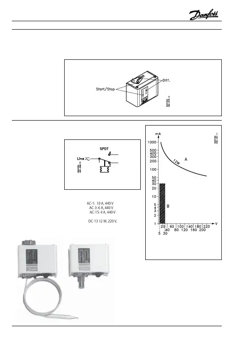
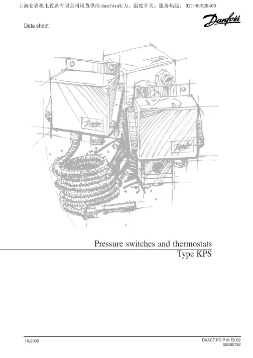
Data sheetPressure switches and thermostatsType KPS10/2003DKACT.PD.P10.E2.02520B07822DKACT.PD.P10.E2.02 Danfoss A/S 10-20033DKACT.PD.P10.E2.02Danfoss A/S 10-2003KPS 43, 45, 47KPS 31, 33KPS 35, 37, 394DKACT.PD.P10.E2.02Danfoss A/S 10-2003Pressure switches and thermostats, type KPSKPS 31:±0.2 bar KPS 39:±3.0 bar KPS 33:±0.3 bar KPS 43:±1.0 bar KPS 35:±0.5 bar KPS 45:±4.0 bar KPS 37:±1.0 barKPS 47:±6.0 barKPS 31:±0.1 bar KPS 39:±0.7 bar KPS 33:±0.2 bar KPS 43:±0.2 bar KPS 35:±0.3 bar KPS 45:±1.0 bar KPS 37:±0.4 barKPS 47:±1.5 barSwitchSingle pole changeover (SPDT)Contact material: Gold-plated silver contact Contact load1. Alternating current:Ohmic:10 A, 440 V, AC-1Inductive: 6 A, 440 V, AC-34 A, 440 V, AC-15Starting current max. 50 A (locked rotor)2. Direct current:12 W, 220 V, DC-13See curve, fig. 4Scale accuracyAmbient temperatureKPS 31 - 39: –40 to +70 °C KPS 43 - 47: –25 to +70 °CTemperature of medium KPS 31 - 39: –40 to +100 °C KPS 43 - 47: –25 to +100 °CFor water and seawater, max. 80°C.Vibration resistanceVibration-stable in the range 2-30 Hz,amplitude 1.1 mm og 30-300 Hz, 4 G.EnclosureIP 67 to IEC 529 an DIN 40050.The pressure switch housing is enamelled pressure die cast aluminium (GD-AlSi 12).The cover is fastened by four screws which are anchored to prevent loss.The enclosure can be sealed with wire.Cable entryPg 13.5 for cable diameters from 5 to 14 mm.IdentificationThe type designation and code no. of the unit is stamped in the side of the housing.Mean value of snap point variation after 400 000 operationsFig. 4. d.c.-loadCurve A gives the maximum load.Hatched area B: Acceptable load for the gold plating of the contact.Materials in contact with the mediumBellows capsule:Deep-drawn plate,material no. 1.0524 (DIN 1624)KPS 31, 33Bellows:Stainless steel,material no. 1.4306 (DIN 17440).Pressure connection:Steel C20,material no. 1.0420 (DIN 1652)KPS 35, 37,39Bellows:Stainless steel,material no. 1.4306 (DIN 17440)Pressure connection:Brass,W.No. 2.0401 (DIN 17660)KPS 43, 45, 47Diaphragm capsule:Nickel-plated brass,DIN 50 968 Cu/Ni 5 (DIN 1756)Diaphragm:Nitrile-Butadien rubberApprovals Ship approvalsEN 60 947-4-1EN 60 947-5-1Det norske Veritas, Norway American Bureau of Shipping Lloyds Register of Shipping, UKFGermanischer Lloyd, Federal Republic of Germany (FRG)Bureau Veritas, FranceIncludes thermostats with fixed sensor and pressure controls with armoured capillary tube.Registro Italiano Navale, ItalyU Underwriters Laboratories Inc., USA PPolski Rejestr Statków, PolandMRS, Maritime Register of Shipping,RussiaNippon Kaiji Kyokai, J apan5DKACT.PD.P10.E2.02Danfoss A/S 10-2003Pressure switches and thermostats, type KPSAccessoriesPartDescriptionCode no.G 3/8 connector, nipple and washer Connector with nipple(10 mm) o.d. x 6.5 mm i.d.), for 017-4368brazingG 3/8 connector, nipple and washer Connector with nipple (10 mm o.d. x 6.5 mm i.d.) for 017-4229weldingReducerG 3/8 x 7/16 - 20 UNF (1/4 flare) reduction with washer017-4205AdaptorG 3/8 x 1/8 - 27 NPT with washer060-3334NippleR 3/8 o.d x 7/16 - 20 UNF (1/4 flare)060-3240NippleG 3/8 A - 1/4 NPT with washer060-3335AdaptorG 3/8 x 1/4 - 18 NPT with washer 060-3336G 1/4 A x G 3/8 A060-3332NippleG 1/4 A x o.d. M10 x 1 with washer 060-3338Damping coil with 1/4 flare connectors and 1 m copper capillary tube. Damping coils used for applications with 3/8 RG Damping coil connector requires the use of 060-0071reducer.For informations about capillary tube lengths, please contact DanfossDamping coilDamping coil with G 3/8 connectors and 1.5 m copper capillary tube060-1047Damping coil with G 3/8 connectors and Armoured damping coil1 m armoured copper capillary tube.060-3333Standard washers included.Dimensions and weightWeight:KPS 31 - 39 approx. 1.0 kg KPS 43 - 47 approx. 1.3 kg6DKACT.PD.P10.E2.02 Danfoss A/S 10-20037DKACT.PD.P10.E2.02Danfoss A/S 10-2003Pressure switches and thermostats, type KPSFig. 10Function1. KPS 31Contacts 1-2 make and contacts 1-4 break when the pressure falls under the set range value. The contacts changeover to their initial position when the pressure again rises to the set range value plus the differential (see fig. 8).I. Alarm for falling pressure given at the set range value.II. Alarm for rising pressure given at the set range value plus the differential.Scale setting2. All other KPS pressure switchesContacts 1-4 make and contacts 1-2 break when the pressure rises above the set range value. The contacts changeover to their initial position when the pressure again fails to the range value minus the differential (see fig. 9).I. Alarm for rising pressure given at the set range value.II. Alarm for falling pressure given at the set range value minus the differential.Scale settingExample 1An alarm must be given when the lubricating oil pressure in a motor fails below 0.8 bar.The alarm is in the form of a lamp.Choose a KPS 31 (range 0 to 2.5 bar).The minimum permissible lubricating oil pressure of 0.8 bar must be set on the range spindle. The differential is fixed at 0.1 bar, i.e.the alarm will not cut out before the pressure rises to 0.9 bar. The lamp must be connected to terminals 1 and 2 in the pressure control.Example 2An alarm must be given by a bell when the pressure in a boiler rises to 10 bar. The normal operating pressure is 9 bar.Choose a KPS 36 (range from 6 to 18 bar).The range value of the pressure control must be set at 10 bar, the differential at 1 bar.The bell must be connected to terminals 1and 4.Example 3The pressure in a start air reservoir must be regulated with a compressor controlled by a KPS pressure switch so that it lies between 30 and 36 bar.Choose a KPS 45 (range 4 to 40 bar).The range value must be set at 36 bar.The differential of 6 bar must be set in accordance with the nomogram, fig. 10, at approx. 2 on the differential scale.The required start function is obtained by connection to terminals 1 and 2 in the pressure control.Mechanical differential Mechanical differentialFig. 8Fig. 98DKACT.PD.P10.E2.02Danfoss A/S 10-2003Pressure switches and thermostats, type KPSEN 60 947-4-1EN 60 947-5-1–10- 30 3-10 80 65 75 110 160 2060L3112 060L3113 KPS 7620- 603-14130-75---060L3118KPS 7720- 603-14130--110--060L3100KPS 7720- 603-14130--160-060L3136KPS 7720- 603-1413065751101602-060L3101060L3102KPS 7720- 603-14130--1101605060L3119060L3120KPS 7750-1004-16200 -75---060L3121KPS 7950-1004-16200--110-060L3103KPS 7950-1004-16200160060L3137KPS 7950-1004-1620065751101602060L3104060L3105KPS 7950-1004-16200--1101605060L3122060L3123KPS 7950-1004-16200--1101608060L3124060L3125KPS 7950-1004-16200-751101603060L3143KPS 7950-1009200-75---060L31411)KPS 7970-120 4.5-18220-75---060L3126KPS 8070-120 4.5-18220--110--060L3127KPS 8070-120 4.5-18220---160-060L3138KPS 8070-120 4.5-18220---200-060L3157KPS 8070-120 4.5-1822065751101602060L3128060L3129KPS 8070-120 4.5-18220-751101603060L3156KPS 8070-120 4.5-18220--1101605060L3130060L3131KPS 8070-120 4.5-18220--1101608060L3132060L3133KPS 8060-1505-2525065751101602060L3106060L3107KPS 8160-1505-25250--1101605060L3134060L3135KPS 8160-1505-252501101608060L3111KPS 8160-1505-25250200060L3110KPS 81100-2006.5-3030065751101602060L3108060L3109KPS 83100-2001830065751101602060L31391)060L31401)KPS 83Thermostats, introductionKPS thermostats are temperature-controlled switches. The position of the contacts depends on the temperature of the sensor and the set scale value. In this series, special attention has been given to meeting demands for : a high level of enclosure,robust and compact construction, resistance to shock and vibration.The KPS series covers most outdoor as well as indoor application requirements.KPS thermostats are suitable for use inmonitoring, alarm and regulation systems in factories, diesel plant, compressors, power stations and on board ship.KPS with rigid sensorKPS with remote sensorKPS with remote sensor and armoured capillary tube Approvals 1) Thermostat with max. reset.When ordering, please state type and code numberTechnical data and ordering Ship approvalsDet norske Veritas, Norway American Bureau of Shipping Lloyds Register of Shipping, UK F Germanischer Lloyd, Federal Republicof Germany (FRG)Bureau Veritas, FranceIncludes thermostats with fixed sensor and pressure controls with armoured capillary tube.U Underwriters Laboratories Inc., USA Registro Italiano Navale, Italy PPolski Rejestr Statków, PolandMRS, Maritime Register of Shipping,RussiaNippon Kaiji Kyokai, J apanCode nos.Mech.Max.Suitable Cap.Setting diff.sensor sensor length Tube Typerangeadjustable/temp.(see also lengthfixed“Accessories”)°C °C °C m m m9DKACT.PD.P10.E2.02Danfoss A/S 10-2003Pressure switches and thermostats, type KPSKPS 76:±3 °C KPS 80:±3 °C KPS 77:±3 °C KPS 81:±6 °C KPS 79:±3 °CKPS 83:±6 °CFig. 1Curve A gives the maximum load.Hatched area B: Acceptable load for the gold plating of the contact.Contact load (Alternating current):Ohmic:10 A, 440 V, AC-1Inductive: 6 A, 440 V, AC-34 A, 440 V, AC-15Starting current max. 50 A (locked rotor)Ambient temperature –40 to +70 °C Vibration resistanceVibration-stable in the range 2-30 Hz,amplitude 1.1 mm og 30-300 Hz, 4 G.EnclosureIP 67 to IEC 529 and DIN 40050.The thermostat housing is enamelled pres-sure die cast aluminium (GID-AlSi 12). The cover is fastened by four screws which are anchored to prevent loss.The enclosure can be sealed with fuse wire.Cable entryPg 13.5 for cable diameters from 5 to 14 mm.IdentificationThe type designation and code no. of the unit is stamped in the side of the housing,Scale accuracySnap point variation after 400 000 operations.KPS 76-83: max. drift 2 °C.SwitchSingle-pole changeover switch (SPDT).Contact material: Gold-plated silver contact.Direct current: 12 W, 220 V, DC-13 – See fig. 1Accessories: Sensor pockets Sensor A Thread Code no.Sensor A Thread Code no.for KPS-thermostats pocket m m Bpocket m m B Brass651/2 NPT060L3265751/2 NPT 060L3264Steel 18/875G 1/2 A060L326775G 1/2 A 060L3262 Brass75G 3/4 A060L326675G 1/2 A (ISO 228/1)060L328175G 3/4 A (ISO 228/1)060L34041101/2 NPT 060L3280Steel 18/8110G 1/2 A 060L3268110G 1/2 A060L32711101/2 NPT 060L3270Brass110G 1/2 A (ISO 228/1)060L3406110G 3/4 A (ISO 228/1)060L3403160G 1/2 A060L3263Steel 18/8160G 1/2 A 060L3269Brass160G 1/2 A (ISO 228/1)060L3407160G 3/4 A (ISO 228/1)060L3405200G 1/2 A060L3206Steel 18/8200G 1/2 A 060L3237Brass 200G 1/2 A (ISO 228/1)060L3408200G 3/4 A 060L3238200G 3/4 A (ISO 228/1)060L3402Brass 250G 1/2 A 060L3254Brass 330G 1/2 A 060L3255Brass 400G 1/2 A 060L3256Brass500G 1/2 A060L3257Part DescriptionNo. of per unitCode no.Clamping bandFor KPS thermostats with remote sensor (L = 392 mm)X017-4204For KPS thermostats with sensor fitted in a sensor pocket.Heat-conductive Compound for filling sensor pocket to improve heat transfer As required 041E0110compound between pocket and sensor. Application range for compound:(4.5 cm 2 tube)–20 to +150 °C, momentarily up to 220°C.Supplied without gland nut,gaskets and washer10DKACT.PD.P10.E2.02 Danfoss A/S 10-200311DKACT.PD.P10.E2.02Danfoss A/S 10-2003Pressure switches and thermostats, type KPSKPS 76–10 - +30 1.1KPS 7720 - 60 1.0 1.4KPS 7950 - 100 1.5 2.2 2.9KPS 8070 - 120 1.72.43.1KPS 8160 - 150 3.7KPS 83100 - 2006.2Scale correctionThe sensor on KPS thermostats contains an adsorption charge. Therefore function is not affected whether the sensor is placed warmer or colder than the remaining part of thethermostatic element (bellows and capillary tube). However, such a charge is to some extent sensitive to changes in thetemperature and bellows and capillary tube.Under normal conditions this is of noimportance, but if the thermostat is to be used in extreme ambient temperatures there will be a scale deviation. The deviation can be compensated for as follows:Scale correction = Z × aZ can be found from fig. 4, while a is the correction factor from the table below.Correction factor a Regulation for thermostats Typerangewith with with rigid 2 and 5 m 8 m °Csensor cap.tube cap.tubeRelative scale setting in %Electrical connectionKPS thermostats are fitted with a Pg 13.5screwed cable entry suitable for cables from 5 to 14 mm. GL approval is conditional on the use of a ship’s cable entry.Contact function is shown in Fig. 5ExamplesExample 1A diesel engine with cooling watertemperature of 85 °C (normal). An alarm must be triggered if the cooling water temperature exceeds 95 °C.Choose a KPS 80 thermostat (range 70 to 120 °C).Main spindle setting: 95 °C.Differential spindle setting: 5 °C.The required alarm function is obtained by connecting to thermostat terminals 1-4. After the system has been in operation, assess the operating differential and make a correction if necessary.Example 2Find the necessary scale correction for a KPS 80 set at 95 °C in 50 °C ambient temperature.The relative scale setting Z can be calculated from the following formula:Setting value – min. scale value max. scale value – min. scale valueRelative scale setting: 95 – 70× 100 = 50%120 – 70Factor for scale deviation Z (fig. 4 page 11),Z ≅ 0.7Correction factor a (table under fig. 4page 11) = 2.4Scale correction = Z × a = 0.7 × 2.4 = 1.7 °C The KPS must be set at 95 + 1.7 = 96.7 °CScale deviation factorFig. 4Fig. 5× 100 = %12DKACT.PD.P10.E2.02 Danfoss A/S 10-2003。


AX427479388119en-000101& Co. OHG DanfossPower Solutions GmbH Krokamp 35D-24539 Neumünster, Germany Phone: +49 4321 871 0DanfossPower Solutions (US) Company 2800 East 13th Street Ames, IA 50010, USA Phone: +1 515 239 6000Installation InformationNo. 4-421April, 1997Copyright Danfoss Corporation, 1997All Rights Reserved Printed in USANeutral Lockout Switch Kits1.Remove the switch from the adaptor.2.Connect a test light with a 12 Vdc power source or a multimeter to the switch terminals. Polarity does not matter. See gure 1-2. If a multimeter is used,set to “ohms” and note that our reference to light “On” is the same as zero ohms and light o is the same as in nite ohms.3.If the light is o when the ball in the end of the switch is not depressed but comes on when the ball is depressed, then it is a normally open (N/0) switch.Caution: Do not depress the ball beyond a point where it is ush with the housing. Permanent damage to the switch could occur.4.If the test light comes on when the ball is not depressed, but goes o when the ball is depressed, it is a normally closed (N/C) switch.Neutral Lockout – Switch Identi cationScrew Terminal SwitchSwitch with Delphi Packard ConnectorDisassemblyNeutral Lockout Switch1.Disconnect wiring from the lockout switch.2.Loosen hex set screws in adapter andremove neutral lockout switch from adapter.3.Remove neutral lockout adapter from servo control valve assembly.Figure 1-1Unexpected movement or operation of equipment may cause serious injury or death. Make sure the battery is discon-not running. Make sure the parking brake is engaged and other peripheral equipment is disengaged.NOTE: Hydraulic uid can leak from the servo control valve assembly when remov-ing the neutral lockout switch and adapter assembly. First shut o the hydraulic reservoir to the pump and drain the hydraulic uid from the pump case to a level below the servo control valve assembly.Reassembly Normally ClosedNote: Reassembly may be done with the Servo Control Valve Assembly on or o the main hydrostatic pump. The nal check of the switch must be done on the pump with all the linkage attached and before engine start-up.Normally Closed (N/C) Neutral Lockout Switch 1.With the switch removed from the adapter, install the adapter into the control assembly. Torque the adapter to 60-72 N·m (44-53 lbf·ft).2.With the adaptor installed, proceed and install the neutral lockout switch into the adapter, again refer to gure 1-1.3.The adjustment procedures for the switch are as follows;(a). First apply a high temperature water resistant grease to the threads. Screw the switch in slowly, while moving the hydraulic control arm back and forth, until “detent” action is detected in the arm movement. See gure 2-1 . Backout the switch until the “detent” action is very slight. Then position the arm out of the detent position ( gure 2 -2 ).(b). Obtain a test light and 12 Vdc power source or use a multimeter. Multimeter use is described under “Switch Identi cation”. Attach the leads from the test light to the(c). Screw the switch in until the light just goes o . Mark this as position “A” with two adjacent marks on the switch adapter. Refer below to gure 2-3. Move the control arm to the detent position and the test light should come back on.(d).Leaving the control arm in the detent position, screw the switch in until the light just goes o . Mark this position “B” on the switch adjacent to the original mark on the adapter.(e).Back out the switch o ne half the distance between “B”and “A”. Refer to gure 2 -3. Torque either hex socket head set screw to 3.2 to 3.8 N·m [28 to 34 lbf·in.] One screw may be inaccessible and does not need to be tightened.4.As a nal precaution, test the switch by moving themachine’s hydrostatic control handle to the neutral position – the light should be on. Move the control handle slightly out of the neutral position and the light should go o .5.Remove test light, reattach original wiring to the Neutral Lockout Switch and put servo control valve assembly into operation.Figure 2-1 Figure 2-2Figure 2-3Reassembly Normally OpenNormally Open (N/O) Neutral Lockout Switch 1.With the switch removed from the adapter, install the adapter into the control assembly, refer to gure 1-1.Torque the adapter to 60-72 N·m (44-53 lbf·ft).2.With the adaptor installed proceed and install the neutral lockout switch into the adapter.3.The adjustment procedures for the switch are as follows;(a). First apply a high temperature water resistent grease to the threads. Screw the switch in slowly, while moving the hydraulic control arm back and forth, until “detent”action is detected in the arm movement. See gure 3-1.Back out the switch until the “detent” action is very slight.Then position the arm out of the detent position. Seegure 3-2.(b).Obtain a test light and 12 Vdc power source or use a multimeter. Multimeter use is described under “Switch Identi cation”. Attach the leads from the test light to the switch. If the light comes on, back the switch out until it goes out.(c).Screw the switch in until the light just comes on.Mark this as position “A” with two adjacent marks on the switch and adapter. Refer to gure 3-3 below. Move the control arm to the detent position and the test light should go back o .(d).Leaving the control arm in the detent position, screw the switch in until the light just comes on. Mark thisposition “B” on the switch adjacent to the original mark on the adapter.(e).Back out the switcho ne half the distance between “B”and “A”. Refer to gure 3-3. Torque either hex socket head set screws to 3.2 to 3.8 N·m [28 to 34 lbf·in.] One screw may be inaccessible and does not need to be tightened.4.As a nal precaution, test the switch by moving the machine’s hydrostatic control handle to the neutralposition – the light should be o . Move the control handle slightly out of the neutral position and the light should go on.5.Remove test light, reattach original wiring to the Neutral Figure 3-1 Figure 3-2Figure 3-3Neutral Lockout – Adaptor Identi cation1.Please note that Eaton has manufactured two sizes ofNeutral Lockout Adaptors. Check to be sure which size youare working with.2.The “old style” adaptor accepts a 3/4" threaded switch, andthe new style accepts a 9/16" threaded switch. See gure4-1.3.When ordering a replacement switch kit the appropriateadaptor is included.Note: New switches are 9/16" threads and will n ot mate witholder style adaptors.3/4" (.750)“Old Style”“New Style”Figure 4-1Neutral Lockout Adaptors4-421Danfoss Power Solutions is a global manufacturer and supplier of high-quality hydraulic and electric components. We specialize in providing state-of-the-art technology and solutions that excel in the harsh operating conditions of the mobile o -highway market as well as the marine sector. Building on our extensive applications expertise, we work closely with you to ensure exceptional performance for a broad range of applications. We help you and other customers around the world speed up system development, reduce costs and bring vehicles and vessels to market faster.Danfoss Power Solutions – your strongest partner in mobile hydraulics and mobile electri cation.Go to for further product information.We o er you expert worldwide support for ensuring the best possible solutions foroutstanding performance. And with an extensive network of Global Service Partners, we also provide you with comprehensive global service for all of our components.Local address:DanfossPower Solutions GmbH & Co. OHG Krokamp 35D-24539 Neumünster, Germany Phone: +49 4321 871 0DanfossPower Solutions ApS Nordborgvej 81DK-6430 Nordborg, Denmark Phone: +45 7488 2222DanfossPower Solutions (US) Company 2800 East 13th Street Ames, IA 50010, USA Phone: +1 515 239 6000DanfossPower Solutions Trading (Shanghai) Co., Ltd.Building #22, No. 1000 Jin Hai Rd Jin Qiao, Pudong New District Shanghai, China 201206Phone: +86 21 2080 6201Danfoss can accept no responsibility for possible errors in catalogues, brochures and other printed material. Danfoss reserves the right to alter its products without notice. This also applies to products already on order provided that such alterations can be made without subsequent changes being necessary in speci cations already agreed.All trademarks in this material are property of the respective companies. Danfoss and the Danfoss logotype are trademarks of Danfoss A/S. All rights reserved.© Danfoss | September 2022Products we o er:•Cartridge valves •DCV directional control valves•Electric converters •Electric machines •Electric motors •Gear motors •Gear pumps •Hydraulic integrated circuits (HICs)•Hydrostatic motors •Hydrostatic pumps •Orbital motors •PLUS+1® controllers •PLUS+1® displays •PLUS+1® joysticks and pedals•PLUS+1® operator interfaces•PLUS+1® sensors •PLUS+1® software •PLUS+1® software services,support and training •Position controls and sensors•PVG proportional valves •Steering components and systems •TelematicsHydro-GearDaikin-Sauer-Danfoss。
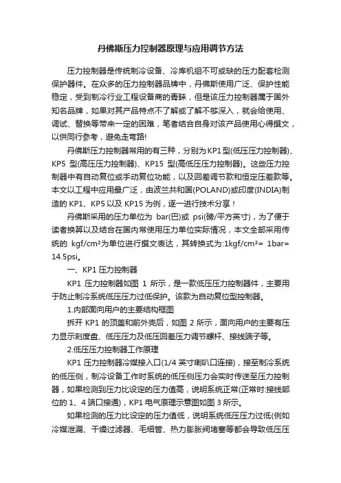
丹佛斯压力控制器原理与应用调节方法压力控制器是传统制冷设备、冷库机组不可或缺的压力配套检测保护器件。
在众多的压力控制器品牌中,丹佛斯使用广泛、保护性能稳定,受到制冷行业工程设备商的青睐,但是该压力控制器属于国外知名品牌,如果对其产品特点不了解或了解不够深入,就会给使用、调试、替换等带来一定的困难,笔者结合自身对该产品使用心得撰文,以供同行参考,避免走弯路!丹佛斯压力控制器常用的有三种,分别为KP1型(低压压力控制器)、KP5型(高压压力控制器)、KP15型(高低压压力控制器)。
这些压力控制器中有自动复位或手动复位功能,以及回差调节款和恒定压差款等。
本文以工程中应用最广泛,由波兰共和国(POLAND)或印度(INDIA)制造的KP1、KP5以及KP15为例,逐一进行技术分享 !丹佛斯采用的压力单位为bar(巴)或psi(磅/平方英寸),为了便于读者换算以及结合在国内常使用压力单位实际情况,本文全部采用传统的kgf/cm²为单位进行撰文表达,其转换式为:1k gf/cm²= 1bar=14.5psi。
一、KP1压力控制器KP1压力控制器如图1所示,是一款低压压力控制器件,主要用于防止制冷系统低压压力过低保护。
该款为自动复位型控制器。
1.内部面向用户的主要结构框图拆开KP1的顶盖和前外壳后,如图2所示,面向用户的主要有压力显示刻度盘、低压压力及低压回差压力调节螺杆、接线端子等。
2.低压压力控制器工作原理KP1压力控制器冷媒接入口(1/4英寸喇叭口连接),接至制冷系统的低压侧,制冷设备工作时系统的低压侧压力会实时传送至压力控制器,如果检测到压力比设定的压力值高,说明系统正常(正常时:接线部位的1、4端口接通),KP1电气原理示意图如图3所示。
如果检测的压力比设定的压力值低,说明系统低压压力过低(例如冷媒泄漏、干燥过滤器、毛细管、热力膨胀阀堵塞等都会导致低压压力过低),为了保护压缩机,不至于在压力过低或者没冷媒的系统中运行时,导致压缩机温升过高、磨损加剧、加速老化等,所以一旦检测到低压压力低于设定值时,就会报警保护,触头1、4断开,切断压缩机电路,1、2接通促使指示灯或喇叭得电报警等,使压缩机保护停机等,实现低压过低保护功能。
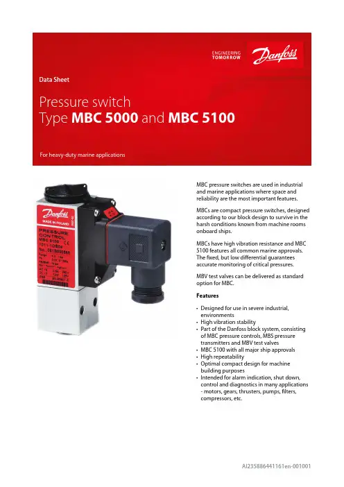
MBC pressure switches are used in industrial and marine applications where space and reliability are the most important features.MBCs are compact pressure switches, designed according to our block design to survive in the harsh conditions known from machine rooms onboard ships.MBCs have high vibration resistance and MBC 5100 features all common marine approvals.The fixed, but low differential guarantees accurate monitoring of critical pressures.MBV test valves can be delivered as standard option for MBC.Features•Designed for use in severe industrial,environments•High vibration stability•Part of the Danfoss block system, consisting of MBC pressure controls, MBS pressure transmitters and MBV test valves•MBC 5100 with all major ship approvals •High repeatability•Optimal compact design for machine building purposes•Intended for alarm indication, shut down,control and diagnostics in many applications - motors, gears, thrusters, pumps, filters,compressors, etc.Product specification Technical dataFigure 1: Electrical connectionf o s s 19.11Figure 3: ThreadFigure 4: Flange connection on MBV 5000 Test ValveMechanical connectionNOTE:Flange connection is not applicable for piston type MBCHow to chooseTo achieve the best operating conditions for MBC pressure controls, it is recommended to apply the following rules of thumb.Choose:Figure 5: MBC 5000, Net weight: 0.25 kgFigure 6: MBC 5100, Net weight: 0.25 kgOrdering standard types(1)Max value, all values lower or equal are correct (2)Preferred versionsOrdering stainless steel types(1)Max value, all values lower or equal are correctPressure switch, MBC 5000 and MBC 5100AccessoriesThe list contains all certificates, declarations, and approvals for this product type. Individual code number may have some or all of these approvals, and certain local approvals may not appear on the list.Some approvals may change over time. You can check the most current status at or contact your local Danfoss representative if you have any questions.CE-marked in accordance with:LVD 2014/35/EU (EN 60947-1, EN 60947-4-1, EN 60947-5-1)Pressure switch, MBC 5000 and MBC 5100Any information, including, but not limited to information on selection of product, its application or use, product design, weight, dimensions, capacity or any other technical data in product manuals, catalogues descriptions, advertisements, etc. and whether made available in writing, orally, electronically, online or via download,shall be considered informative, and is only binding if and to the extent, explicit reference is made in a quotation or order confirmation. Danfoss cannot accept any responsibility for possible errors in catalogues, brochures, videos and other material. Danfoss reserves the right to alter its products without notice. This also applies to products ordered but not delivered provided that such alterations can be made without changes to form, fit or function of the product. All trademarks in this material are property of Danfoss A/S or Danfoss group companies. Danfoss and the Danfoss logo are trademarks of Danfoss A/S. All rights reserved.Online supportDanfoss offers a wide range of support along with our products, including digital product information, software,mobile apps, and expert guidance. See the possibilities below.The Danfoss Product StoreThe Danfoss Product Store is your one-stop shop for everything product related—no matter where you are in the world or what area of the cooling industry you work in. Get quick access to essential information like product specs, code numbers, technical documentation, certifications, accessories,and more.Start browsing at .Find technical documentationFind the technical documentation you need to get your project up and running. Get direct access to our official collection of data sheets, certificates and declarations, manuals and guides, 3D models and drawings, case stories, brochures, and much more.Start searching now at /en/service-and-support/documentation .Danfoss LearningDanfoss Learning is a free online learning platform. It features courses and materials specifically designed to help engineers, installers, service technicians, and wholesalers better understand the products, applications, industry topics, and trends that will help you do your job better.Create your Danfoss Learning account for free at /en/service-and-support/learning .Get local information and supportLocal Danfoss websites are the main sources for help and information about our company andproducts. Find product availability, get the latest regional news, or connect with a nearby expert—all in your own language.Find your local Danfoss website here: /en/choose-region .。
danfoss三通阀门使用说明Danfoss三通阀门是指采用高强度不锈钢、合金、陶瓷等材料制成的一种阀门。
其主要特点在于强度高、耐磨损、寿命长。
特别适用于化工、石油、冶金、机械等行业。
本阀门的使用寿命一般为40-50年左右,在使用过程中如出现漏水等问题应及时检修,避免造成不必要的损失。
1. Danfoss三通阀门不允许用手直接接触阀门内的介质,否则将损坏阀门结构。
如必须接触时,应注意防止液体飞溅到阀体上,造成损坏。
当阀门开启时,手不能接触到阀门内部,请使用其它保护工具对阀门进行检修。
由于阀门内部泄漏或损坏引起阀门关闭不严密或停止工作时,使阀门处于关闭状态。
如操作不当将会造成泄漏或损坏阀门内部元件。
2.阀门安装前应检查各零件、管件是否完整以及内部有无油污、铁锈等。
在安装阀门前,必须先清洗管道和阀门,以免安装时出现卡塞等现象。
安装阀门时,应使阀门置于合适的位置。
阀门的密封面和球面之间的间隙应保持在1-2 mm内,以免影响密封效果。
在安装阀门前一定要将阀门打开检查密封是否完好。
在管道上安装阀门时应尽量减少阀门之间的距离。
阀门的安装方向应与管道上安装阀门时所选定的方向一致。
关闭时阀门应处于开启状态。
安装阀门后应进行检验,确保密封性能良好。
阀门应有良好的密封性能,且密封面不得有砂眼、气孔、裂纹、疏松和缩孔等缺陷,密封性能应符合表1-3要求。
3.在安装过程中应注意的是必须安装好法兰和垫片,以免阀门因振动、冲击而损坏。
如果没有法兰和垫片,可以安装在法兰上,也可以安装在阀门上。
安装时要注意法兰上与阀门壳体垂直、相互平行,在安装时应使阀门在水平位置,不能与管道平行以免影响阀门的密封。
安装法兰和密封垫片时应注意保证法兰的密封面和垫片压紧,以免阀门因振动、冲击而损坏。
Danfoss三通阀门使用说明对阀门各部位的安装要求严格执行下列规定:首先要进行预处理在阀门安装前应对管道和阀门内部进行清洗,检查是否存在污物、异物等杂质。
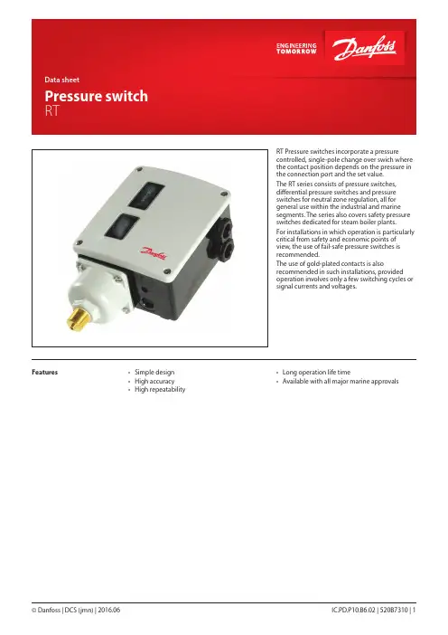
RT Pressure switches incorporate a pressure controlled, single-pole change over swich where the contact position depends on the pressure in the connection port and the set value.The RT series consists of pressure switches, differential pressure switches and pressure switches for neutral zone regulation, all for general use within the industrial and marine segments. The series also covers safety pressure switches dedicated for steam boiler plants.For installations in which operation is particularly critical from safety and economic points of view, the use of fail-safe pressure switches is recommended.The use of gold-plated contacts is also recommended in such installations, provided operation involves only a few switching cycles or signal currents and voltages.Features• Simple design• High accuracy• High repeatability • Long operation life time• Available with all major marine approvalsData sheet | Pressure switch, RT Note:in addition we refer to the certificates, the copies of which can be ordered from Danfoss y CE marked in accordance with EN 60947-4/-5 for sale in Europey Further, the RT 19 , RT 30, RT 35, RT 112 W, RT 33, RT 31 and RT 32 series is CE markd in accordance with PED 97/23/EC, category IV, safety equipment.Approvals Overview/SurveyData sheet | Pressure switch, RTTechnical dataand code nos.When ordering, please state typeand code number.The type designationfor the letters below means:A: Unit suitable for the medium ammoniaL: Unit with neutral zonePressure switchesRT 113for manual setting;cover with windowsRT 116for tamper proof;cap and blank coverRT 262 ADifferential pressure switchPressure switches with adjustable neutral zoneDifferential pressure switches1)Supplied with ø6 / ø10 mm nipple. / 2)Non-snap action contacts (see spare parts and accessories, contact system 017-018166)3) With SPST and SPDT contact system for alarm and cut off function at 0.8 and 1 bar1) Supplied with ø6 / ø10 mm weld nipple1) Supplied with ø6 / ø10 mm weld nipple. / 2) With seal capPreferred versionsData sheet | Pressure switch, RT B: Safety units with external reset S: Safety units with internal resetThe designation letters mean:A: Units suitable for the medium ammonia.W: Units for control purposes.Pressure switches for steam plant, PED approved acc. to EN 12953-9 and EN 12922-11For rising pressureFor falling pressurePressure switches for low pressure steam plant (pressure monitoring)- not PED approvedTechnical data and orderingTechnical dataPreferred versionsData sheet | Pressure switch, RTMaterials in contact with the mediumMaterials in contact with the medium, PED approved switchesData sheet | Pressure switch, RTb. All other RT pressure switchesWhen the pressure falls to the set range value, contacts 1-2 make and contacts 1-4 brake. The contacts changeover to their original position when the pressure again rises to the set range plus the differential (see fig. 5).I. Alarm for falling pressure givenat the set range value.II. Alarm for rising pressure given at the set range value plus the differential.Units with min. reset can only be resetat a pressure corresponding to the set range value plus the differential.Functiona. RT 19, RT 30, and pressure switcheswith max. resetWhen the pressure exceeds the set range value, contacts 1-4 make and contact 1-2 brake. The contacts changeover to their initial position when the pressure falls to the range value minus the differential (see fig. 4). I.Alarm for rising pressure givenat the set range value.II. Alarm for falling pressure given at the set range value minus the differential.Units with max. reset can only be reset at a pressure corresponding to the set range value minus the differential, or a lower pressure.Data sheet | Pressure switch, RTExample 1An extra cooling water pump must start if the cooling water pressure falls below 6 bar, and must stop when the pressure exceeds 7 bar.Choose an RT 116 with a range of 1 – 10 bar and an adjustable differential of 0.2 – 1.3 bar.The start pressure of 6 bar must be set on the range scale. The differential must be set as the difference between the stop pressure (7 bar) and the start pressure (6 bar) = 1 bar. According to fig. 3, the differential setting disc must be set on 8.Example 2The burner on a steam boiler must cut out when the pressure exceeds 17 bar. Automatic restart must not occur.Choose an RT 19B with external reset. If extra safety is demanded, an RT 19S with internal max. reset can be used.The range is 5 – 25 bar and the differential is fixed at approx. 1 bar. The range scale must be set at 17 bar. After cut-out of the burner, manual reset is possible only when the pressure had fallen to the setting of 17 bar minus the differential: in this case, 16 bar and below.Example 3The min. permissible lubricating oil pressure for a gear is 3 bar. Reset must not be possible until the reason for oil pressure failure has been investigated. Choose an RT 200 with min. reset.The range value must be set while reading the range scale. Manual reset is possible only when the pressure has reached 3.2 bar (the differential is fixed at 0.2 bar or higher).Function (continuation)Functional description of RT unitswith fail-safe designFail-safe function for falling pressureFig. 5a shows a cross-section of a bellowselement for the RT 32W with fail-safe functionfor falling pressure. On rising pressure thecontact arm is actuated to break the connectionbetween terminals 1 and 2.On falling pressure the contact arm is actuatedto break the connection between terminals1 and 4. If a defect occurs in the bellows thesetting spring actuates the contact arm to breakthe connection between terminals 1 and 4, asin the case of falling pressure. This will occurirrespective of the pressure on the bellows.Fail-safe function for rising pressureFig. 5b shows a cross-section through a bellowselement for the RT 30W with fail-safe for risingpressure. On rising pressure the contact armis actuated to break the connection betweenterminals 1 and 2 .If a defect occurs in the inner bellows thepressure is led to the outer bellows. The outerbellows has an area three times as large as theinner bellows. The connection between terminals1 and2 becomes broken.If a defect occurs in the outer bellows, there willbe atmospheric pressure in the gap between thetwo bellows. This actuates the contact system tobreak the connection between terminals 1 and2. The important factor with the double bellowsdesign is the vacuum between the two bellows,and that in case of bellows break, no media willleak into the environment.Fig 5aFig. 5bData sheet | Pressure switch, RTPressure switches for liquid level control RT 1133. Connection to the side of the tankwith the RT 113 below the liquid levelWhere possible, this form of connection shouldbe used. If an air-absorbing liquid like oil isinvolved, it is preferable to 1 and 2. The resultingrange setting is the distance from the liquidsurface to the centre of the diaphragm housing.4. Connection in the tank with the RT 113above the liquid levelThis method is for use with air-absorbing liquidswhere connection type 3 is not possible. Theshortest horizontal tube length is determinedas described in 2. A shut-off valve is installedbetween the oil tank and water reservoir shownso that impurities can be drained from the waterreservoir through a bottom drain plug. Freshwater can then be poured into the reservoirthrough a filling connector in its top.The RT 113 pressure switch can be usedto control the liquid level in open tanks.Fig. 6 shows in principle, four different typesof installation.1. With air bell (see “Accessories”)For control purpose, the air bell should beinstalled 20 – 40 mm below the lowest liquidlevel. In addition, the tube between the RT 113and the air bell must be absolutely airtight. Ifonly an indication is required, the bell can beplaced 100 mm below the max. level. The RT 113must be set at 0 cm wg and the differential discon 1.2. Connection to the side of the tankwith the RT 113 above the liquid levelThe horizontal tube A must have a certain lengthin relation to the vertical tube B in order toensure reliable control. The length ofA can befound from fig. 7, using B and the range settingpressure C.Data sheet | Pressure switch, RT Application5. Setting knob 9. Range scale40. Neutral zone discRT-L pressure switches are fitted with a switch with an adjustable neutral zone. This enables the units to be used for floating control.The terminology involved is explained below.Floating controlA form of discontinuous control where thecorrecting element (e.g. valve, damper, or similar) moves towards one extreme position at a rate independent of the magnitude of the error when the error exceeds a definit positive value, and towards the opposite extreme position when the error exceeds a definite negative value.HuntingPeriodic variations of the controlled variable from the fixed reference.Neutral zoneThe interval in the controlled variable in which the correcting element does not respond (see fig. 13)The contact system in neutral zone units cannot be exchanged, as the contact system adjustment is adjusted to the other parts of the unit.Setting of neutral zoneThe range is set using the setting knob (5) fig. 8 while reading the range scale (9). The pressure set is the break pressure for contacts 1-4 (see fig. 13).The required neutral zone can be found in the diagram for the unit concerned. The position at which the neutral zone disc (40) must be set can be read from the lower scale in the diagram. The function can be seen in fig. 13.Data sheet | Pressure switch, RTExampleTogether with a VLT® static frequency converter, RT 200L neutral zone pressure switches can be used for the infinite control of a pump in, for example, a pressure boosting plant.In this case, the pump must be up and downregulated at 32 m and 25 m wg.The RT 200L must be set using the setting knob (5) fig. 8 page 9 at 3.5 bar (35 m wg) minus the fixed differential of 0.2 bar.The range setting is 3.5 - 0.2 = 3.3 bar.The neutral zone, 35 - 32 = 3 m wg,corresponding to 0.3 bar, must be set on the neutral zone disc (40) fig. 8 page 9. According to the diagram fig. 12 the disc setting is 1 or just over. A more accurate setting can be obtained by using the test setup shown in fig. 14.Setting of neutral zone© Danfoss | DCS (jmn) | 2016.06Data sheet | Pressure switch, RT IC.PD.P10.B6.02 | 520B7310 | 11ApplicationControl and monitoring of pressure differentials A differential pressure switch is a pressure controlled switch that cuts in and cuts out the current dependent on the pressure differential between the counteracting bellowselements and the set scale value. This unit is also available with an adjustable neutral zone (like the RT-L which is described on page 9.The setting disc (5) becomes accessible when the front cover is removed. The differential pressure is set by turning the disc with a screwdriver while reading the scale (9).For differential pressure switches with a changeover contact system, the contactdifferential is given as the differential pressure switches have a fixed differential. In units with an adjustable neutral zone, the neutral zone disc must also be set. See diagram in fig. 16.5. Setting disc 9. Range scaleSettingNote :When installing, the low pressure connection (LP) must always be upwards© Danfoss | DCS (jmn) | 2016.06Data sheet | Pressure switch, RT 12 | 520B7310 | IC.PD.P10.B6.02Functiona. Units with changeover switch (SPDT)b. Units with adjustable neutral zone (SPDTNP)If the differential pressure rises above the set value plus the differential, contacts 1-4 make.If the pressure falls by the amount of thedifferential (which is fixed in this unit), contacts 1-4 break. If the pressure falls to the neutral zone minus the differential, contacts 1-2 make. When the differential pressure rises again by an amount corresponding to the differential, contacts 1-2 break again.The contact function can be summed up as follows:I. Setting disc set for falling differential pressure.II. Neutral zone disc set for rising differential pressure.Example 1When the differential pressure exceeds 1.3 bar, a filter needs cleaning. The static pressure over the filter is 10 bar.According to the ordering table on page 4, the choice is an RT 260A (the RT 262A has a max. operating pressure on the low pressure side (LP) of 6 bar and is therefore not suitable for this application).Setting: Since a signal is required for rising differential pressure, the setting becomes 1.3 - 0.3 bar = 1.0 bar.Example 2The speed of a circulation pump must becontrolled to give a constant differential pressure of 10 m wg in a heating plant. The static plant pressure is 4 bar. The choice is an RT 262AL.The differential disc (5) fig. 15 page 13, must be set at 1 bar (10 m wg) minus the fixed differential of 0.1 bar, i.e. 0.9 bar. The neutral zone disc is factory-set (marked in red).I. Contacts make when differential pressure falls below the range scale setting.© Danfoss | DCS (jmn) | 2016.06RT 260A / RT 260ALRT 262A / RT 262A /RT 263ALData sheet | Pressure switch, RT IC.PD.P10.B6.02 | 520B7310 | 13Dimensions [mm] and weights [kg]Data sheet | Pressure switch, RT Spare parts and accessoriesSwitches1)At load types with low currents/voltages contact failure may occure on the silver contacts because of oxidation. In systems where such a contact failure is of great importance (alarm etc.), gold plated contacts are recommended.Contact systems for neutral zone units are not available as spare parts. Exchange not possible, as the contact system adjustment is adjusted to the other parts of the unit.The switch contacts are shown in the position they assume on falling pressure/temperature, i.e. after downward movement of the RT main spindle. The setting pointer of the control shows the scale value at which contact changeover occurs on falling pressure/temperature. An exception is switch no. 017-403066 with max. reset where the setting pointer shows the scale value at which contact changeover occurs on rising pressure.Data sheet | Pressure switch, RT© Danfoss | DCS (jmn) | 2016.06IC.PD.P10.B6.02 | 520B7310 | 15© Danfoss | DCS (jmn) | 2016.06Data sheet | Pressure switch, RT 16 | 520B7310 | IC.PD.P10.B6.02RT units have two mounting holes which become accessible when the front cover isremoved. Units fitted with switch 017-018166*) must be installed with the setting knob upwards. When installing differential pressure switches, the low pressure side (marked LP) must be installed upwards.The other pressure switches in the RT series can be installed in any position, expect that on plant subjected to severe vibrations it is advantageous to have the screwed cable entry downwards.*) Contact system with snap-action contact. See spare parts and accessories, page 13.Pressure connectionWhen fitting or removing pressure lines, the spanner flats on the pressure connection should be used to apply counter-torque.Steam plantTo protect the pressure element against temperature in excess to the maximumtemperature of the medium 150 °C (RT 113 90 °C), the insertion of water-filled loop is recommended. Water systemsWater in the pressure element is not harmful, but if frost is likely to occur a water-filled pressure element may burst. To prevent this happening, the pressure control can be allowed to operate on an air cushion.Media resistanceSee table of materials in contact with the medium. If seawater is involved, diaphragm pressure switches types KPS 43, KPS 45 and KPS 47 are recommended.PulsationsThe pressure switch must be connected in such a way that the pressure element is affected by pulsations as little as possible. A damping coil can be inserted (see “Accessories”). With strongly pulsating media, diaphragm pressure switches types KPS 43, KPS 45 and KPS 47 can be advantageous.Installation5. Setting knob 9. Range scale19. Differential setting disc SettingThe range is set by using the setting knob (5) while at the same time reading the scale (9). Tools must be used to set pressure switches fitted with a seal cap.In units having a fixed differential, the difference between cut-in and cut-out pressures is of course determined. On units having an adjustabledifferential the front cover must be removed. The differential disc (19) must be set in accordance with the diaphragm.Fig. 1. Positioning of unit© Danfoss | DCS (jmn) | 2016.06IC.PD.P10.B6.02 | 520B7310 | 17Selection of differentialTo ensure that the plant functions properly, a suitable differential pressure is necessary. Too small a differential will give rise to short running periods with a risk of hunting. Too high a differential will result in large pressure oscillations.Differential scale values are guiding.Installation。

EN 60947-4-1EN 60947-5-1CCC, China Compulsory Certifi cateBellows versions Repeatability Diaphragm versionsPiston versions± 0.2 % FS (typ.)± 0.5 % FS (max.)± 0.5 % FS (typ.)± 1 % FS (max.)± 1 % FS (typ.)± 1 % FS (max.)Response time < 4 ms Max. switch frequency 10/min (0.16 Hz)Diff erentialsee page 3Permissible operating pressure see page 3Burst pressure see page 3Life time Mechanical for diaphragm and bellows Mechanical for piston typeElectrical at max. contact load > 400,000 cycles >1 million cycles > 100,000 cycles• Designed for use in severe industrialenvironments• High vibration stability• Part of the Danfoss block system, consisting of MBC pressure controls, MBS pressure transmitters and MBV test valves• MBC 5100 with all major ship approvals • H igh repeatability• Optimal compact design for machine building purposes• Intended for alarm indication, shut down, control and diagnostics in manyapplications - motors, gears, thrusters, pumps, fi lters, compressors etc.Heavy duty pressure controls MBC 5000 and MBC 5100FeaturesShip approvalsMBC 5100Lloyd’s Register of Shipping Germanischer LloydRINA, Registro Italiano Navale NKK, Nippon Kaiji Kyokai DNV, Det Norske VeritasBV, Bureau VeritasAmerican Bureau of Shipping KRS, Korean Register of ShippingRMRS, Russian Maritime Register of ShippingData sheetPerformanceTechnical data Electrical specifi cationsSwitch SPDT Contact loadAC 110 A, 250 V AC 150.5A, 250 V AC 33A, 250 VDC 1312 W, 125 VEnvironmental conditionsOperationBellows versions TemperatureDiaphragm versions Piston versions TransportBellows versions Diaphragm versionsPiston versions -40 to +85 °C-10 to +85 °C -40 to +85 °C -50 to +85 °C -50 to +85 °C -40 to +85 °CEnclosure IP 65, IEC 529Vibration stability Sinusoidal20 g, 25 Hz - 2 kHzpiston type 4.4g, 25-200 HzIEC 68-2-6IEC 60068-2-27ApprovalsINDUSTRIAL CONTROLS IC.PD.P10.A2.02- 520B22172 IC.PD.P10.A2.02- 520B2217IC.PD.P10.A2.02- 520B2217 34 IC.PD.P10.A2.02- 520B2217。
丹佛斯Danfoss压力开关KP361、环境温度:-40 - +65°C (+80°C 最多持续2 小时).2、DIN认证单元:40 - +65°C (+80°C 最多持续2 小时).3、最大工作压力= 32 bar, KP 6 = 46.5 bar4、最大测试压力= 35 bar, KP 6 = 46.5 bar5、触点负荷, AC:6、AC1: 16 A, 400 V7、AC3: 16 A, 400 V8、AC15: 10 A, 400 V9、最大启动电流(L.R.): 112 A, 400 V10、触点负荷, DC:11、DC13: 12 W, 220 V 控制电流郭工0595 28 767 808phone 152 **** ****特性值类型KP35质量[公斤] 0.328 [kg]环境温度[摄氏度] -40 - 65 °C环境温度[华氏度] -40 - 149 °F是否氨用否认证 C UL US接口尺寸G 1/4 A连接标准ISO 228-1接口类型管螺纹触点功能镀金触点,单刀双掷触点负荷12 W/220 V dc触点负荷Max.regul.: 100 mA/30 V ac/dc触点负荷Min: 1mA/5 V ac/5 V dc触点负荷警报: Max. 10 A/400 V ac回差[bar] 0.7 - 4.0 bar回差[psi] 10.2 - 58.0 psi封装等级IP30最大测试压力[bar] 14 bar最大工作压力[bar] 10 bar最大工作压力[psig] 145 psig包装格式Multi pack每标准包装的数量36 pc调节范围[bar] -0.2 - 7.5 bar调节范围[psig] -2.9 - 108.7 psigDanfoss KP系列压力开关适用于工业应用中的调节、监控和报警系统。
KP系列适用于气体介质,避免过低的吸气压力和过高的排气压力。
丹佛斯压差控制阀说明书丹佛斯压力开关KP系列的安装及使用众所周知,在一般的制冷系统中,都会用到高低压力开关,用来控制压缩机的启停、风机启停,从而确保制冷系统的正常运行。
今天和大家简单的交流一下压力开关KP的安装和使用。
KP的安装在托架上或者在纯平表面上安装KP压力控制器。
也可以在压缩机上安装压力控制器。
在不利条件下,角铁托架可能会增强安装平面的振动。
因此在出现强烈振动的地方应始终使用墙装托架。
如果有出现水滴或水雾的风险,则必须使用附带的顶板。
顶板可将外壳的防护等级增加到IPIP 44并且适用于所有的KP压力控制器。
要达到IP 44的防护等级,必须将控制器安装在角铁托架(060-105666)或墙板托架(060-105566)上来盖住其背板上的孔。
包含自动复位功能的所有装置均配有顶板。
带有手动复位的装置也可以使用顶板,但在这种情况下,必须单独购买(单压,代码为060-109766;双压,代码为060-109866)。
如果装置要用在污浊的条件下或者暴露在浓重的水雾中—从顶部或从侧面—则必须安装防护帽。
防护帽可与角铁托架或墙装托架一起使用。
如果装置存在暴露在多水环境中的风险,则当产品安装在特殊IP55外壳中后可达到更高的防IP 55护等级。
IP 55外壳有单压(060-033066)和双压(060-035066)可供选择。
控制器的压力管连接必须始终以正确的方式安装到管路上,即使液体不会聚积在波纹管底部。
尤其是在以下情况下,很可能会出现该风险:装置位于很低的周围环境中时,例如在气流中在管路的底部进行连接时。
这样的液体可能会损坏高压控制器。
因此,压缩机的振动得不到抑制并可能引发触点颤动。
放置多余的毛细管如果发生振动,多余的毛细管可能会破裂并导致失去所有的系统充注物。
因此遵守以下原则便显得非常重要:当直接安装在压缩机上时:固定毛细管,使压缩机/控制器装置作为一个整体一起振动。
必须盘起并扎紧多余的毛细管。
注意:根据EN规则,禁止使用毛细管来连接安全压力控制器。
Revised 10/01/88I–3557-SWet Armature Solenoid Operated Directional ValveDG4S*-01*A-W(3)-*-50Service GuideVickers by Danfoss®Directional ValvesAX439457235961en-000101’d) (F3 Viton - 5 req’d)Model CodePrinted in U.S.A.For satisfactory service life of these components, use full ow ltration to provide uid which meets ISO cleanliness code 20/18/15 or cleane r. Selections from Danfoss OF P, OFR, and OFRS series are recommended.Danfoss Power Solutions is a global manufacturer and supplier of high-quality hydraulic and electric components. We specialize in providing state-of-the-art technology and solutions marine sector. Building on our extensive applications expertise, we work closely with you to ensure exceptional performance for a broad range of applications. We help you and other customers around the world speed up system development, reduce costs and bring vehicles and vessels to market faster.Danfoss Power Solutions – your strongest partner in mobile hydraulics and mobile Go to for further product information.outstanding performance. And with an extensive network of Global Service Partners, we also provide you with comprehensive global service for all of our components.Local address:DanfossPower Solutions GmbH & Co. OHG Krokamp 35D-24539 Neumünster, Germany Phone: +49 4321 871 0DanfossPower Solutions ApS Nordborgvej 81DK-6430 Nordborg, Denmark Phone: +45 7488 2222DanfossPower Solutions (US) Company 2800 East 13th Street Ames, IA 50010, USA Phone: +1 515 239 6000DanfossPower Solutions Trading (Shanghai) Co., Ltd.Building #22, No. 1000 Jin Hai Rd Jin Qiao, Pudong New District Shanghai, China 201206Phone: +86 21 2080 6201Danfoss can accept no responsibility for possible errors in catalogues, brochures and other printed material. Danfoss reserves the right to alter its products without notice. This also applies to productsagreed.All trademarks in this material are property of the respective companies. Danfoss and the Danfoss logotype are trademarks of Danfoss A/S. All rights reserved.© Danfoss | December 2022•Cartridge valves •DCV directional control valves•Electric converters •Electric machines •Electric motors •Gear motors •Gear pumps •Hydraulic integrated circuits (HICs)•Hydrostatic motors •Hydrostatic pumps •Orbital motors •PLUS+1® controllers •PLUS+1® displays •PLUS+1® joysticks and pedals•PLUS+1® operator interfaces•PLUS+1® sensors •PLUS+1® software •PLUS+1® software services,support and training •Position controls and sensors•PVG proportional valves •Steering components and systems •TelematicsHydro-GearDaikin-Sauer-Danfoss。
kp36压力开关技术参数
【实用版】
目录
1.概述
2.技术参数详解
3.应用领域
4.结论
正文
1.概述
kp36 压力开关是一种用于测量和控制流体介质压力的设备。
它可以在各种工业和民用领域中使用,以确保系统的安全运行。
kp36 压力开关具有高可靠性和稳定性,能够在恶劣的环境条件下正常工作。
2.技术参数详解
kp36 压力开关的主要技术参数如下:
- 测量范围:0-100MPa
- 控制精度:±1%
- 工作温度:-20℃-80℃
- 电源电压:DC 24V
- 输出信号:4-20mA 或 0-10V
- 接口方式:M12×1
此外,kp36 压力开关还具有抗干扰能力强、响应速度快等特点。
3.应用领域
kp36 压力开关广泛应用于石油、化工、冶金、电力、船舶、制药等
行业。
在这些领域中,kp36 压力开关可以有效地监测流体介质的压力,确保系统的正常运行,防止事故的发生。
4.结论
kp36 压力开关具有较高的测量精度和稳定性,能够在恶劣的环境条件下正常工作。
它的广泛应用有助于确保各行业的生产安全。
丹佛斯Danfoss压力开关KP36
1、环境温度:-40 - +65°C (+80°C 最多持续2 小时).
2、DIN认证单元:40 - +65°C (+80°C 最多持续2 小时).
3、最大工作压力= 32 bar, KP 6 = 46.5 bar
4、最大测试压力= 35 bar, KP 6 = 46.5 bar
5、触点负荷, AC:
6、AC1: 16 A, 400 V
7、AC3: 16 A, 400 V
8、AC15: 10 A, 400 V
9、最大启动电流(L.R.): 112 A, 400 V
10、触点负荷, DC:
11、DC13: 12 W, 220 V 控制电流
郭工0595 28 767 808
phone 152 **** ****
特性值
类型KP35
质量[公斤] 0.328 [kg]
环境温度[摄氏度] -40 - 65 °C
环境温度[华氏度] -40 - 149 °F
是否氨用否
认证 C UL US
接口尺寸G 1/4 A
连接标准ISO 228-1
接口类型管螺纹
触点功能镀金触点,单刀双掷
触点负荷12 W/220 V dc
触点负荷Max.regul.: 100 mA/30 V ac/dc
触点负荷Min: 1mA/5 V ac/5 V dc
触点负荷警报: Max. 10 A/400 V ac
回差[bar] 0.7 - 4.0 bar
回差[psi] 10.2 - 58.0 psi
封装等级IP30
最大测试压力[bar] 14 bar
最大工作压力[bar] 10 bar
最大工作压力[psig] 145 psig
包装格式Multi pack
每标准包装的数量36 pc
调节范围[bar] -0.2 - 7.5 bar
调节范围[psig] -2.9 - 108.7 psig
Danfoss KP系列压力开关适用于工业应用中的调节、监控和报警系统。
KP系列适用于气体介质,避免过低的吸气压力和过高的排气压力。
控制器也可用于制冷和空调系统中制冷压缩机和带风冷冷凝器风扇的启动和停止。
KP 型压力控制器带有单级双郑转换开关,开关位置根据压力控制器的设定值和接口处的压力确定。