创成式外形设计、曲面优化、展开外形和 BiW 模板
- 格式:doc
- 大小:500.01 KB
- 文档页数:33

第三章C A T I A V5创成式外形设计目录1产品介绍................................................................................................. 错误!未指定书签。
2图标功能介绍(基本概念、基本界面介绍) ................................................ 错误!未指定书签。
2.1线框造型(Wireframe)图标 ..................................................... 错误!未指定书签。
2.2曲面造型(Surfaces)............................................................... 错误!未指定书签。
2.3几何操作(Operations) ........................................................... 错误!未指定书签。
2.4分析(Analysis)....................................................................... 错误!未指定书签。
2.5约束(Constraints).................................................................. 错误!未指定书签。
2.6注解(Annotations)................................................................. 错误!未指定书签。
2.7高级复制工具(AdvancedReplicationTools) ........................... 错误!未指定书签。
CATIA V5版本具有:1.重新构造的新一代体系结构为确保CATIA产品系列的发展,CATIA V5新的体系结构突破传统的设计技术,采用了新一代的技术和标准,可快速地适应企业的业务发展需求,使客户具有更大的竞争优势。
2.支持不同应用层次的可扩充性CATIA V5对于开发过程、功能和硬件平台可以进行灵活的搭配组合,可为产品开发链中的每个专业成员配置最合理的解决方案。
允许任意配置的解决方案可满足从最小的供货商到最大的跨国公司的需要。
3.与NT和UNIX硬件平台的独立性CATIA V5是在Windows NT平台和UNIX平台上开发完成的,并在所有所支持的硬件平台上具有统一的数据、功能、版本发放日期、操作环境和应用支持。
CATIA V5在Windows平台的应用可使设计师更加简便地同办公应用系统共享数据;而UNIX平台上NT风格的用户界面,可使用户在UNIX平台上高效地处理复杂的工作。
4.专用知识的捕捉和重复使用CATIA V5结合了显式知识规则的优点,可在设计过程中交互式捕捉设计意图,定义产品的性能和变化。
隐式的经验知识变成了显式的专用知识,提高了设计的自动化程度,降低了设计错误的风险。
5.给现存客户平稳升级CATIA V4和V5具有兼容性,两个系统可并行使用。
对于现有的CATIA V4用户,V5年引领他们迈向NT世界。
对于新的CATIA V5客户,可充分利用CATIA V4成熟的后续应用产品,组成一个完整的产品开发环境。
航空航天:CATIA 源于航空航天工业,是业界无可争辩的领袖。
以其精确安全,可靠性满足商业、防御和航空航天领域各种应用的需要。
在航空航天业的多个项目中,CATIA 被应用于开发虚拟的原型机,其中包括Boeing飞机公司(美国)的Boeing 777 和Boeing 737,Dassault 飞机公司(法国)的阵风(Rafale)战斗机、Bombardier飞机公司(加拿大)的Global Express 公务机、以及Lockheed Martin飞机公司(美国)的Darkstar无人驾驶侦察机。

CATIA创成式外形造型设计第三章 CATIA V5 创成式外形设计目录1产品介绍 (8)2图标功能介绍(基本概念、基本界面介绍) (8)2.1线框造型(Wireframe)图标 (8)2.2曲面造型(Surfaces) (15)2.3几何操作(Operations) (18)2.4分析(Analysis) (27)2.5约束(Constraints) (29)2.6注解(Annotations) (29)2.7高级复制工具(Advanced Replication Tools) (30)2.8用户特征(UserFeature) (33)2.9高级曲面造型(Advanced Surfaces) (33)2.10与创成式外形设计有关的工具 (34)3软件环境设定(Customizing Settings) (39)3.1一般环境参数设定(General选项) (39)3.2显示环境参数设定(Display选项) (40)3.3零件文档参数设定(Part Document选项) (40)4功能详细介绍 (41)4.1线框造型功能(Wireframes) (41)4.1.1........................................................ 点的生成(Point)详解414.1.2............................. 创建多点/平面(Points and Planes Repetition)详解424.1.3............................................... 创建极值元素(Extremum)详解444.1.4.................................... 创建极坐标极值元素(Polar Extremum)详解454.1.5....................................................... 直线的生成(Line)详解474.1.6.................................................... 折线的生成(Polyline)详解484.1.7...................................................... 平面的生成(Plane)详解484.1.8.................................. 在两平面间创建多平面(Planes Between)详解494.1.9........................................................ 圆的生成(Circle)详解504.1.10.................................................... 拐角的生成(Corner)详解514.1.11.............................................. 桥接曲线(Connect Curve)详解4.1.13........................................................ 样条线(Spline)详解544.1.14......................................................... 螺旋线(Helix)详解554.1.15..................................................... 平面螺旋线(Spiral)详解564.1.16....................................................... 脊骨曲线(Spine)详解574.1.17................................................. 平行线(Parallel Curve)详解584.1.18.................................................... 投影线(Projection)详解604.1.19.................................................. 组合投影线(Combine)详解614.1.20............................................... 反射曲线(Reflect Curve)详解624.1.21................................................. 相交元素(Intersection)详解624.2曲面造型功能(Surfaces) (64)4.2.1........................................................ 拉伸面(Extrude)详解644.2.2..................................................... 回转面(Revolution)详解654.2.3.......................................................... 球面(Sphere)详解664.2.4....................................................... 偏移曲面(Offset)详解674.2.5....................................................... 扫描曲面(Sweep)详解684.2.6...................................... 自适应扫描曲面(Adaptative Sweep)详解764.2.7.......................................................... 填充曲面(Fill)详解784.2.8......................................................... 放样曲面(Loft)详解794.2.9........................................................ 过渡曲面(Blend)详解824.3几何操作功能(Operations) (84)4.3.1....................................................... 合并几何体(Join)详解844.3.2...................................................... 修补曲面(Healing)详解864.3.3................................................ 光顺曲线(Curve smooth)详解4.3.5............................................. 分解几何元素(Disassemble)详解894.3.6......................................................... 切割元素(Split)详解904.3.7......................................................... 修剪元素(Trim)详解914.3.8.................................................. 提取边界线(Boundary)详解934.3.9.................................................... 提取几何体(Extract)详解944.3.10................................... 提取多边界(Multiple Edge Extraction)详解954.3.11............................................... 两曲面倒圆(Shape Fillet)详解954.3.12.................................................. 棱线倒圆(Edge Fillet)详解974.3.13...................................... 变半径倒圆(Variable Radius Fillet)详解994.3.14........................................... 面-面倒圆(Face-Face Fillet)详解1004.3.15......................................... 三面相切倒圆(Tritangent Fillet)详解1014.3.16................................................. 平移几何体(Translate)详解1014.3.17.................................................... 旋转几何体(Rotate)详解1024.3.18................................................. 对称几何体(Symmetry)详解1034.3.19................................................... 缩放几何体(Scaling)详解1034.3.20..................................................... 仿射对象(Affinity)详解1044.3.21............................... 将几何体移动到另一坐标系上(Axis to Axis)详解1054.3.22............................................. 延长曲线/曲面(Extrapolate)详解1054.3.23....................................... 曲线/曲面反向(Invert Orientation)详解1064.3.24.............................................. 提取最近部分几何体(Near)详解1074.3.25........................................................ 创建规则(Law)详解1074.4分析功能(Analysis) (108)1094.4.3.............................................. 拔模角分析(Draft Analysis)详解1104.4.4.................................... 曲面曲率映射分析(Mapping Analysis)详解1104.4.5....................................... 曲线曲率分析(Curvature Analysis)详解1114.5约束功能(Constraints) (111)4.5.1..................................... 对单个几何元素施加约束(Constraint)详解1114.5.2................... 在几何元素间施加约束(Constraint defined in dialog box)详解1124.6注解功能(Annotations) (112)4.6.1.................................. 创建带引出箭头的注解(Text with Leader)详解1124.6.2................................................ 创建超级链接(Flag Note)详解1134.7高级复制功能(Advanced Replication Tools) (114)4.7.1............................................. 对象复制(Object Repetition)详解1144.7.2............................................ 矩行阵列(Rectangle Pattern)详解1154.7.3.............................................. 圆形阵列(Circular Pattern)详解1164.7.4................................... 复制Open Body(Duplicate OpenBody)详解1184.7.5...................................... 创建高级复制(PowerCopy Creation)详解1194.7.6......................... 将高级复制存入目录(PowerCopy Save In Catalog)详解1204.7.7.................................. 实例化高级复制(Instantiate PowerCopy)详解1204.8用户特征功能(UserFeature) (121)4.8.1..................................... 创建用户特征(UserFeature Creation)详解1214.8.2...................... 将用户特征存入目录中(UserFeature Save In Catalog)详解1214.8.3................................. 实例化用户特征(Instantiate UserFeature)详解1214.9高级曲面造型功能(Advanced Surfaces) (121)4.9.1............................... 线与点的展开(Developing wire and points)详解1224.9.2..................................................... 交汇曲面(Junction)详解4.9.4...................................... 根据曲线替换变形曲面(Wrap Curve)详解1264.10与创成式外形设计有关的工具 (128)4.10.1..................................................... 更新模型(Update)详解1294.10.2............................................ 生成新坐标系(Axis System)详解1294.10.3..................................... 显示历史树(Show Historical Graph)详解1304.10.4...................................... 在支撑面上工作(Work On Support)详解1304.10.5................................................. 捕捉点(Snap to Point)详解1314.10.6.................................... 创建笛卡尔格栅组(Create a New Set)详解1314.10.7........................... 生成带或不带历史记录的几何体(Create Datum)详解1324.10.8................................................................ 插入元素详解1334.10.9........................................ 实体选择器(Select Current Tool)详解1335应用实例 (134)5.1实例一筋类曲面 (134)5.2实例二三倒圆曲面交汇处的曲面处理方法 (137)5.2.1............................................................. 三角边曲面补丁法1375.2.2................................................................. 变半径倒圆法1385.2.3............................................................... 四边曲面补丁法1395.3实例三六倒圆曲面交汇处的曲面处理方法 (141)5.4实例四多倒圆曲面交汇处的曲面处理方法 (143)5.5实例五瓶子曲面 (146)5.6实例六旋钮 (148)1 产品介绍CATIA V5的创成式外形设计(GSD)模块包括线框和曲面造型功能,它为用户提供了一系列应用广泛、功能强大、使用方便的工具集,以建立和修改用于复杂外形设计所需的各种曲面。

第三章 CATIA V5 创成式外形设计目录1产品介绍 (6)2图标功能介绍(基本概念、基本界面介绍) (6)2.1线框造型(Wireframe)图标 (6)2.2曲面造型(Surfaces) (13)2.3几何操作(Operations) (17)2.4分析(Analysis) (25)2.5约束(Constraints) (27)2.6注解(Annotations) (28)2.7高级复制工具(Advanced Replication Tools) (29)2.8用户特征(UserFeature) (31)2.9高级曲面造型(Advanced Surfaces) (31)2.10与创成式外形设计有关的工具 (33)3软件环境设定(Customizing Settings) (38)3.1一般环境参数设定(General选项) (38)3.2显示环境参数设定(Display选项) (39)3.3零件文档参数设定(Part Document选项) (39)4功能详细介绍 (40)4.1线框造型功能(Wireframes) (40)4.1.1点的生成(Point)详解 (40)4.1.2创建多点/平面(Points and Planes Repetition)详解 (41)4.1.3创建极值元素(Extremum)详解 (43)4.1.4创建极坐标极值元素(Polar Extremum)详解 (45)4.1.5直线的生成(Line)详解 (47)4.1.6折线的生成(Polyline)详解 (48)4.1.7平面的生成(Plane)详解 (49)4.1.8在两平面间创建多平面(Planes Between)详解 (50)4.1.9圆的生成(Circle)详解 (50)4.1.10拐角的生成(Corner)详解 (51)4.1.11桥接曲线(Connect Curve)详解 (52)4.1.12圆锥线(Conic)详解 (53)4.1.13样条线(Spline)详解 (55)4.1.14螺旋线(Helix)详解 (56)4.1.15平面螺旋线(Spiral)详解 (57)4.1.16脊骨曲线(Spine)详解 (59)4.1.17平行线(Parallel Curve)详解 (60)4.1.18投影线(Projection)详解 (61)4.1.19组合投影线(Combine)详解 (62)4.1.20反射曲线(Reflect Curve)详解 (63)4.1.21相交元素(Intersection)详解 (64)4.2曲面造型功能(Surfaces) (65)4.2.1拉伸面(Extrude)详解 (66)4.2.2回转面(Revolution)详解 (67)4.2.3球面(Sphere)详解 (68)4.2.4偏移曲面(Offset)详解 (69)4.2.5扫描曲面(Sweep)详解 (70)4.2.6自适应扫描曲面(Adaptative Sweep)详解 (78)4.2.7填充曲面(Fill)详解 (80)4.2.8放样曲面(Loft)详解 (82)4.2.9过渡曲面(Blend)详解 (85)4.3几何操作功能(Operations) (86)4.3.1合并几何体(Join)详解 (87)4.3.2修补曲面(Healing)详解 (88)4.3.3光顺曲线(Curve smooth)详解 (90)4.3.4恢复被剪切的曲面或曲线(Untrim)详解 (91)4.3.5分解几何元素(Disassemble)详解 (92)4.3.6切割元素(Split)详解 (93)4.3.7修剪元素(Trim)详解 (94)4.3.8提取边界线(Boundary)详解 (96)4.3.9提取几何体(Extract)详解 (97)4.3.10提取多边界(Multiple Edge Extraction)详解 (98)4.3.11两曲面倒圆(Shape Fillet)详解 (99)4.3.12棱线倒圆(Edge Fillet)详解 (100)4.3.13变半径倒圆(Variable Radius Fillet)详解 (102)4.3.14面-面倒圆(Face-Face Fillet)详解 (103)4.3.15三面相切倒圆(Tritangent Fillet)详解 (104)4.3.16平移几何体(Translate)详解 (105)4.3.17旋转几何体(Rotate)详解 (106)4.3.18对称几何体(Symmetry)详解 (106)4.3.19缩放几何体(Scaling)详解 (107)4.3.20仿射对象(Affinity)详解 (108)4.3.21将几何体移动到另一坐标系上(Axis to Axis)详解 (108)4.3.22延长曲线/曲面(Extrapolate)详解 (109)4.3.23曲线/曲面反向(Invert Orientation)详解 (110)4.3.24提取最近部分几何体(Near)详解 (111)4.3.25创建规则(Law)详解 (111)4.4分析功能(Analysis) (112)4.4.1曲面连接性检查(Connect Checker)详解 (112)4.4.2曲线连接性检查(Curve Connect Checker)详解 (113)4.4.3拔模角分析(Draft Analysis)详解 (114)4.4.4曲面曲率映射分析(Mapping Analysis)详解 (114)4.4.5曲线曲率分析(Curvature Analysis)详解 (115)4.5约束功能(Constraints) (115)4.5.1对单个几何元素施加约束(Constraint)详解 (115)4.5.2在几何元素间施加约束(Constraint defined in dialog box)详解 (116)4.6注解功能(Annotations) (116)4.6.1创建带引出箭头的注解(Text with Leader)详解 (116)4.6.2创建超级链接(Flag Note)详解 (117)4.7高级复制功能(Advanced Replication Tools) (118)4.7.1对象复制(Object Repetition)详解 (118)4.7.2矩行阵列(Rectangle Pattern)详解 (119)4.7.3圆形阵列(Circular Pattern)详解 (120)4.7.4复制Open Body(Duplicate OpenBody)详解 (122)4.7.5创建高级复制(PowerCopy Creation)详解 (123)4.7.6将高级复制存入目录(PowerCopy Save In Catalog)详解 (124)4.7.7实例化高级复制(Instantiate PowerCopy)详解 (124)4.8用户特征功能(UserFeature) (125)4.8.1创建用户特征(UserFeature Creation)详解 (125)4.8.2将用户特征存入目录中(UserFeature Save In Catalog)详解 (125)4.8.3实例化用户特征(Instantiate UserFeature)详解 (125)4.9高级曲面造型功能(Advanced Surfaces) (125)4.9.1线与点的展开(Developing wire and points)详解 (126)4.9.2交汇曲面(Junction)详解 (128)4.9.3曲面凸起(Bump)详解 (129)4.9.4根据曲线替换变形曲面(Wrap Curve)详解 (131)4.10与创成式外形设计有关的工具 (134)4.10.1更新模型(Update)详解 (134)4.10.2生成新坐标系(Axis System)详解 (135)4.10.3显示历史树(Show Historical Graph)详解 (135)4.10.4在支撑面上工作(Work On Support)详解 (136)4.10.5捕捉点(Snap to Point)详解 (136)4.10.6创建笛卡尔格栅组(Create a New Set)详解 (137)4.10.7生成带或不带历史记录的几何体(Create Datum)详解 (138)4.10.8插入元素详解 (138)4.10.9实体选择器(Select Current Tool)详解 (139)5应用实例 (139)5.1实例一筋类曲面 (139)5.2实例二三倒圆曲面交汇处的曲面处理方法 (143)5.2.1三角边曲面补丁法 (143)5.2.2变半径倒圆法 (144)5.2.3四边曲面补丁法 (145)5.3实例三六倒圆曲面交汇处的曲面处理方法 (147)5.4实例四多倒圆曲面交汇处的曲面处理方法 (149)5.5实例五瓶子曲面 (152)5.6实例六旋钮 (154)1 产品介绍CATIA V5的创成式外形设计(GSD)模块包括线框和曲面造型功能,它为用户提供了一系列应用广泛、功能强大、使用方便的工具集,以建立和修改用于复杂外形设计所需的各种曲面。

第三章 CATIA V5 创成式外形设计目录1产品介绍 (6)2图标功能介绍(基本概念、基本界面介绍) (6)2.1线框造型(Wireframe)图标 (6)2.2曲面造型(Surfaces) (7)2.3几何操作(Operations) (7)2.4分析(Analysis) (9)2.5约束(Constraints) (9)2.6注解(Annotations) (9)2.7高级复制工具(Advanced Replication Tools) (10)2.8用户特征(UserFeature) (10)2.9高级曲面造型(Advanced Surfaces) (10)2.10与创成式外形设计有关的工具 (10)3软件环境设定(Customizing Settings) (12)3.1一般环境参数设定(General选项) (12)3.2显示环境参数设定(Display选项) (13)3.3零件文档参数设定(Part Document选项) (13)4功能详细介绍 (14)4.1线框造型功能(Wireframes) (14)4.1.1点的生成(Point)详解 (14)4.1.2创建多点/平面(Points and Planes Repetition)详解 (14)4.1.3创建极值元素(Extremum)详解 (15)4.1.4创建极坐标极值元素(Polar Extremum)详解 (16)4.1.5直线的生成(Line)详解 (18)4.1.6折线的生成(Polyline)详解 (18)4.1.7平面的生成(Plane)详解 (18)4.1.8在两平面间创建多平面(Planes Between)详解 (19)4.1.9圆的生成(Circle)详解 (19)4.1.10拐角的生成(Corner)详解 (20)4.1.11桥接曲线(Connect Curve)详解 (20)4.1.12圆锥线(Conic)详解 (21)4.1.13样条线(Spline)详解 (22)4.1.14螺旋线(Helix)详解 (23)4.1.15平面螺旋线(Spiral)详解 (24)4.1.16脊骨曲线(Spine)详解 (24)4.1.17平行线(Parallel Curve)详解 (25)4.1.18投影线(Projection)详解 (26)4.1.19组合投影线(Combine)详解 (27)4.1.20反射曲线(Reflect Curve)详解 (27)4.1.21相交元素(Intersection)详解 (27)4.2曲面造型功能(Surfaces) (28)4.2.1拉伸面(Extrude)详解 (28)4.2.2回转面(Revolution)详解 (29)4.2.3球面(Sphere)详解 (30)4.2.4偏移曲面(Offset)详解 (30)4.2.5扫描曲面(Sweep)详解 (31)4.2.6自适应扫描曲面(Adaptative Sweep)详解 (39)4.2.7填充曲面(Fill)详解 (40)4.2.8放样曲面(Loft)详解 (41)4.2.9过渡曲面(Blend)详解 (44)4.3几何操作功能(Operations) (45)4.3.1合并几何体(Join)详解 (45)4.3.2修补曲面(Healing)详解 (47)4.3.3光顺曲线(Curve smooth)详解 (47)4.3.4恢复被剪切的曲面或曲线(Untrim)详解 (48)4.3.5分解几何元素(Disassemble)详解 (48)4.3.6切割元素(Split)详解 (49)4.3.7修剪元素(Trim)详解 (50)4.3.8提取边界线(Boundary)详解 (50)4.3.9提取几何体(Extract)详解 (51)4.3.10提取多边界(Multiple Edge Extraction)详解 (52)4.3.11两曲面倒圆(Shape Fillet)详解 (52)4.3.12棱线倒圆(Edge Fillet)详解 (53)4.3.13变半径倒圆(Variable Radius Fillet)详解 (55)4.3.14面-面倒圆(Face-Face Fillet)详解 (55)4.3.15三面相切倒圆(Tritangent Fillet)详解 (55)4.3.16平移几何体(Translate)详解 (56)4.3.17旋转几何体(Rotate)详解 (56)4.3.18对称几何体(Symmetry)详解 (57)4.3.19缩放几何体(Scaling)详解 (57)4.3.20仿射对象(Affinity)详解 (57)4.3.21将几何体移动到另一坐标系上(Axis to Axis)详解 (57)4.3.22延长曲线/曲面(Extrapolate)详解 (58)4.3.23曲线/曲面反向(Invert Orientation)详解 (58)4.3.24提取最近部分几何体(Near)详解 (58)4.3.25创建规则(Law)详解 (59)4.4分析功能(Analysis) (59)4.4.1曲面连接性检查(Connect Checker)详解 (59)4.4.2曲线连接性检查(Curve Connect Checker)详解 (60)4.4.3拔模角分析(Draft Analysis)详解 (60)4.4.4曲面曲率映射分析(Mapping Analysis)详解 (60)4.4.5曲线曲率分析(Curvature Analysis)详解 (60)4.5约束功能(Constraints) (60)4.5.1对单个几何元素施加约束(Constraint)详解 (61)4.5.2在几何元素间施加约束(Constraint defined in dialog box)详解 (61)4.6注解功能(Annotations) (61)4.6.1创建带引出箭头的注解(Text with Leader)详解 (61)4.6.2创建超级链接(Flag Note)详解 (61)4.7高级复制功能(Advanced Replication Tools) (62)4.7.1对象复制(Object Repetition)详解 (62)4.7.2矩行阵列(Rectangle Pattern)详解 (62)4.7.3圆形阵列(Circular Pattern)详解 (63)4.7.4复制Open Body(Duplicate OpenBody)详解 (64)4.7.5创建高级复制(PowerCopy Creation)详解 (65)4.7.6将高级复制存入目录(PowerCopy Save In Catalog)详解 (65)4.7.7实例化高级复制(Instantiate PowerCopy)详解 (65)4.8用户特征功能(UserFeature) (66)4.8.1创建用户特征(UserFeature Creation)详解 (66)4.8.2将用户特征存入目录中(UserFeature Save In Catalog)详解 (66)4.8.3实例化用户特征(Instantiate UserFeature)详解 (66)4.9高级曲面造型功能(Advanced Surfaces) (66)4.9.1线与点的展开(Developing wire and points)详解 (67)4.9.2交汇曲面(Junction)详解 (68)4.9.3曲面凸起(Bump)详解 (69)4.9.4根据曲线替换变形曲面(Wrap Curve)详解 (70)4.10与创成式外形设计有关的工具 (72)4.10.1更新模型(Update)详解 (73)4.10.2生成新坐标系(Axis System)详解 (73)4.10.3显示历史树(Show Historical Graph)详解 (73)4.10.4在支撑面上工作(Work On Support)详解 (73)4.10.5捕捉点(Snap to Point)详解 (73)4.10.6创建笛卡尔格栅组(Create a New Set)详解 (73)4.10.7生成带或不带历史记录的几何体(Create Datum)详解 (74)4.10.8插入元素详解 (74)4.10.9实体选择器(Select Current Tool)详解 (74)5应用实例 (75)5.1实例一筋类曲面 (75)5.2实例二三倒圆曲面交汇处的曲面处理方法 (79)5.2.1三角边曲面补丁法 (79)5.2.2变半径倒圆法 (80)5.2.3四边曲面补丁法 (81)5.3实例三六倒圆曲面交汇处的曲面处理方法 (83)5.4实例四多倒圆曲面交汇处的曲面处理方法 (85)5.5实例五瓶子曲面 (88)5.6实例六旋钮 (90)1 产品介绍CATIA V5的创成式外形设计(GSD)模块包括线框和曲面造型功能,它为用户提供了一系列应用广泛、功能强大、使用方便的工具集,以建立和修改用于复杂外形设计所需的各种曲面。
第三章创成式外形风格造型设计(GSD)CATIA V5的创成式外形风格造型设计模块包括(GSD)线框和曲面造型功能的组合,它为用户提供了一系列功能强大、使用方便的工具集以建立和修改复杂外形设计所需的各种曲面。
创成式外形风格造型设计采用基于特征的设计方法和全相关技术,在设计过程中能有效地捕捉设计者的设计意图,因此,极大地提高设计质量与效率,为后续设计更改提供强有力的技术支持。
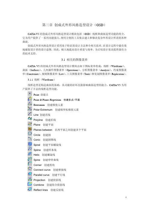
3.1 相关的图像菜单CATIA V5的创成式外形风格造型设计模块由如下图标菜单组成:线框(Wireframe)、曲面(Surfaces)、几何操作图像菜单(Operations)、分析图像菜单(Analysis)、约束图像菜单(Constraints)、规则图像菜单(Law)、工具图像菜单(Tools)和复制图像菜单(Replication)。
3.1.1 线框(Wireframe)线框造型是构造曲面的基础,其功能的好坏直接影响曲面造型的能力。
CATIA V5为用户提供了丰富的线框造型功能。
Point 创建点Point & Planes Repetition创建多点/平面Extremum创建极值元素Polar Extremum创建极坐标极值元素Line 创建直线Polyline创建折线Plane创建平面Planes between在两平面之间创建多个平面Circle创建圆Conic创建圆锥线Spiral创建平面螺旋线Spline创建样条线Helix创建螺旋线Spine创建脊骨曲线Corner创建拐角Connect curve创建桥接线Parallel curve创建平行线Projection创建投影线Combine创建组合投影线Reflect lines创建反射线Intersection创建交线3.1.2 曲面(Surfaces)曲面造型广泛应用于汽车外形、模具型面等设计上。
CATIA V5为用户提供了丰富而实用的曲面造型功能(如下所示)。
创成式曲面设计模块论述引言创成式曲面设计模块是一种使用户能够通过自由绘制、变形和编辑曲面来创造自定义形状的设计工具。
该模块在许多领域中都得到了广泛的应用,包括工业设计、汽车设计、航空航天工程等。
在本文中,我们将对创成式曲面设计模块的原理、应用和发展进行论述。
创成式曲面设计模块原理创成式曲面设计模块的原理基于参数化曲面的设计和变形。
通过定义曲面上的控制点和控制网格,用户可以通过拖动和调整这些控制点和网格来实现曲面的自由变形。
通常,创成式曲面设计模块使用的是贝塞尔曲线和贝塞尔曲面来描述曲面的形状,这些曲线和曲面是由控制点确定的。
用户可以通过在曲面上添加、删除和调整控制点来调整曲面的形状。
创成式曲面设计模块的应用工业设计在工业设计中,创成式曲面设计模块可以用于创建各种产品的外观曲面。
通过自由绘制和调整曲面的形状,设计师可以快速设计出符合需求的产品外观。
这种模块可以帮助设计师节省时间和精力,提高设计效率。
汽车设计在汽车设计中,创成式曲面设计模块可以用于创建汽车的外型曲面。
设计师可以通过调整曲面的参数来改变汽车的线条和曲率,从而实现不同风格和外观的汽车设计。
创成式曲面设计模块还可以与其他工具相结合,如汽车动态仿真软件,以实现更真实的汽车设计和性能分析。
航空航天工程在航空航天工程中,创成式曲面设计模块可以用于设计飞机和航天器的曲面结构。
通过自由绘制和编辑曲面,工程师可以优化飞行器的空气动力学性能,同时满足结构强度和航空工程要求。
创成式曲面设计模块还可以与其他工程仿真软件相结合,以验证设计方案的合理性。
创成式曲面设计模块的发展随着计算机技术和图形学的快速发展,创成式曲面设计模块在功能和性能方面得到了不断的提升。
现代创成式曲面设计模块具有更强大的绘制和编辑功能,可以实现更复杂和精细的曲面设计。
同时,创成式曲面设计模块还可以与其他设计软件和工程仿真软件进行集成,实现更高效和全面的设计流程。
未来,创成式曲面设计模块还有许多发展的方向。


Entering the Generative Shape DesignWorkbenchThis first task shows you how to enter the Generative Shape Design workbench and open a wireframe design part.Before starting this scenario, you should be familiar with the basic commands common to all workbenches. These are described in the Infrastructure User's Guide.1.Select Shape-> Generative Shape Design from the Start menu.The Shape Design workbench is displayed.The New Part name dialog box may appear depending on the way you customized your session. It provides a field for entering the name you wish to assign to the part, an option that enables hybrid design an two other options to insert a geometrical set and/or an ordered geometrical set in the part to be created.If you select Enable hybrid design, the capability then applies to all the bodies you will create in your CATIA session (and not only to the new CATPart document you are opening). Consequently, if your session contains CATPart documents already includingtraditional bodies, the new bodies you will create subsequently in these documents will possibly include wireframe and surfaceelements.To facilitate your design, It is therefore recommended that you do not change this setting during your session.For more information, refer to the Part Document chapter inCustomizing section of the Part Design documentation.2.Select File -> Open and navigate to the samples directory.3.Select the GettingStartedShapeDesign.CATPart document.A wireframe design part is displayed:o You can add the Generative Shape Design workbench to your Favorites, using the Tools ->Customize item.For more information, refer to the Infrastructure User'sGuide.o If you wish to use the whole screen space forthe geometry, remove the specification tree by selectingthe View -> Specifications c ommand or pressing F3.Lofting, Offsetting and IntersectingThis task shows you how to create a multi-sections and an offset surfaces as well as an intersection.1.Click the Multi-sections Surface icon .The Multi-sections Surface Definition dialog box appears.2.Select the two section curves.3.Click within the Guides window then select the two guide curves.4.Click OK to create the multi-sections surface.5.Click the Offset icon .6.Select the multi-sections surface.7.Enter an offset value of 2mm.The offset surface is displayed normal to the multi-sections surface.8.Click OK to create the offset surface.9.Click the Intersection icon .The Intersection dialog box appears.10.Select the offset surface then the first plane (Plane.2) to create theintersection between these two elements.11.Click OK in the dialog box.The created elements are added to the specification tree:12.Splitting, Lofting and FilletingThis task shows how to split surfaces then create a multi-sections surface and two fillets.1.Click the Split icon .The Split Definition dialog box appears.2.Select the offset surface by clicking on the portion that you want to keepafter the split.3.Select the first plane (Plane.2) as cutting element.4.Click OK to split the surface.5.Repeat the previous operations by selecting the multi-sections surfacethen the second plane (Plane.3) to define the intersection first, then to cut the surface.6.Click OK to split the surface.7.Click the Multi-sections Surface icon .The Multi-sections Surface Definition dialog box appears.8.Select the intersection edges of the two split surfaces as sections.9.Click OK to create the multi-sections surface between the two splitsurfaces.10.Click the Shape Fillet icon .The Fillet Definition dialog box appears.11.Select the first split surface as the first support element (Split.3).12.Select the multi-sections surface you just created as the second supportelement (Multi-sections Surface.3).13.Enter a fillet radius of 3mm.The orientations of the surfaces are shown by means of arrows.14.Make sure that the surface orientations are correct (arrows pointingdown) then click OK to create the first fillet surface.15.Repeat the filleting operation, clicking the icon, then selecting thesecond split surface as the first support element.16.Select the previously created filleted surface as the second supportelement.17.Enter a fillet radius of 3mm.18.Make sure that the surface orientations are correct (arrows pointing up)then click OK to create the second filleted surface.The created elements are added to the specification tree:Sweeping and FilletingThis task shows how to create swept surfaces and fillets on both sides of the part.You will use the profile element on the side of the part for this. In this task you will also create a symmetrical profile element on the opposite side of the part.1.Click the Swept Surface icon .The Swept Surface Definition dialog box appears.2.Click the Explicit sweep icon.3.Select the profile element (Corner.1).4.Select the guide curve (Guide.1).5.Select the central curve (Spline.1) as the spine.6.Click OK to create the swept surface.7.Click the Symmetry icon .The Symmetry Definition dialog box appears.8.Select the profile element to be transformed by symmetry.9.Select the YZ plane as reference element.10.Click OK to create the symmetrical profile element.11.Click the Sweep icon again.12.Select the profile (Symmetry.3) and the guide curve (Guide.2).13.Select the central curve (Spline.1) as the spine.14.Click OK to create the swept surface.15.To create a fillet between the side portion and the central part click theShape Fillet icon .16.Select the side sweep element and the central portion of the part, thenenter a fillet radius of 1mm (make sure the arrows are pointing up).17.Click Preview to preview the fillet, then OK to create it.18.Repeat the filleting operation between the other sweep element and thecentral portion of the part, and entering a fillet radius of 1mm (make sure the arrows are pointing up).19.Click OK to create the fillet.The created elements are added to the specification tree:20.Using the Historical GraphThis task shows how to use the Historical Graph's commands and contextualcommands.Open any .CATPart document.1.Select the element for which you want to display the historical graph.2.Click the Show Historical Graph icon .The Historical Graph dialog box appears.In this case, you can examine the history of events that led to theconstruction of the Multi-sections surface.1 element. Each branch ofthe graph can be expanded or collapsed depending on the level of detail required.The following icon commands are available:Add Graph Adds a selected element to the graphRemove Graph Removes a selected element from the graphReframe Centers the graph in the windowSurface or Part graphrepresentationGives a horizontal or verticalrepresentationParametersDisplays any parameters associated withthe elements in the graphConstraintsDisplays any constraints associated withthe elements in the graph3.Right-click anywhere in the historical graph to display the contextualmenu:Hide/Show Hides or shows an elementProperties Displays the properties of an element ReframegraphCenters the graph in the windowPrint whole Allows you to obtain a print of the graphGraph All Displays the whole graph of the part (as well as the roots and their first parents)Clean Graph C lears the graph from the window Refresh Refreshes the graph displayExpand All Displays the parents of the elements in the graph (but not the roots)4.Transforming the PartThis task shows you how to modify the part by applying an affinity operation.1.Click the Affinity icon .The Affinity Definition dialog box appears.2.Select the end section profile to be transformed by the affinity.3.Specify the characteristics of the axis system to be used for the affinityoperation:o point PT0 as the origino plane XY as reference planeo X axis as the reference axis.4.Specify the affinity ratios: X=1, Y=1 and Z=1.5.5.Click OK to create the new profile.6.Edit the definition of the multi-sections surface (Multi-sectionsSurface.1), by double-clicking it, then select the second section, click the Replace button and select the new profile.7.Click OK in the dialog box.8.If needed, click the Update icon to update your design.Multi-selection is available. Refer to Selecting Using Multi-Output to find out how to display and manage the list of selected elements.9.。
Entering the Generative Shape DesignWorkbenchThis first task shows you how to enter theGenerative Shape Design workbench and opena wireframe design part.Before starting this scenario, you should be familiarwith the basic commands common to allworkbenches. These are described in theInfrastructure User's Guide.1.Select Shape-> Generative Shape Designfrom the Start menu.The Shape Design workbench is displayed.The New Part name dialog box mayappear depending on the way youcustomized your session. It provides afield for entering the name you wish toassign to the part, an option thatenables hybrid design an two otheroptions to insert a geometrical setand/or an ordered geometrical set inthe part to be created.If you select Enable hybrid design, thecapability then applies to all the bodiesyou will create in your CATIA session(and not only to the new CATPartdocument you are opening).Consequently, if your session containsCATPart documents already includingtraditional bodies, the new bodies youwill create subsequently in thesedocuments will possibly includewireframe and surface elements.To facilitate your design, It is thereforerecommended that you do not changethis setting during your session.For more information, refer to the PartDocument chapter in Customizingsection of the Part Designdocumentation.2.Select File -> Open and navigate to thesamples directory.3.Select theGettingStartedShapeDesign.CATPartdocument.A wireframe design part is displayed:o Y ou canaddtheGenerativeShapeDesignworkbenchto yourFavorites,usingtheTools->Customizeitem.Formoreinformation,referto theInfrastructureUser'sGuide.o If youwish tousethewholescreenspacefor thegeometry,remove thespecificationtree byselecting theView->Specificationsc ommand orpressing F3. Lofting, Offsetting and IntersectingThis task shows you how to create amulti-sections and an offset surfaces as well as an intersection.1.Click the Multi-sections Surface icon.The Multi-sections Surface Definitiondialog box appears.2.Select the two section curves.3.Click within the Guides window thenselect the two guide curves.4.Click OK to create the multi-sectionssurface.5.Click the Offset icon.6.Select the multi-sections surface.7.Enter an offset value of 2mm.The offset surface is displayed normal to the multi-sections surface.8.Click OK to create the offset surface.9.Click the Intersection icon.The Intersection dialog box appears.10.Select the offset surface then the firstplane (Plane.2) to create theintersection between these twoelements.11.Click OK in the dialog box.The created elements are added to the specification tree:12.Splitting, Lofting and FilletingThis task shows how to split surfaces then create a multi-sections surface and two fillets.1.Click the Split icon.The Split Definition dialog box appears.2.Select the offset surface by clicking onthe portion that you want to keep afterthe split.3.Select the first plane (Plane.2) ascutting element.4.Click OK to split the surface.5.Repeat the previous operations byselecting the multi-sections surfacethen the second plane (Plane.3) todefine the intersection first, then to cut the surface.6.Click OK to split the surface.7.Click the Multi-sections Surface icon.The Multi-sections Surface Definitiondialog box appears.8.Select the intersection edges of the twosplit surfaces as sections.9.Click OK to create the multi-sectionssurface between the two split surfaces.10.Click the Shape Filleticon.The Fillet Definition dialog box appears.11.Select the first split surface as the firstsupport element (Split.3).12.Select the multi-sections surface youjust created as the second supportelement (Multi-sections Surface.3). 13.Enter a fillet radius of 3mm.The orientations of the surfaces areshown by means of arrows.14.Make sure that the surface orientationsare correct (arrows pointing down) thenclick OK to create the first fillet surface.15.Repeat the filleting operation, clickingthe icon, then selecting the second split surface as the first support element.16.Select the previously created filletedsurface as the second support element.17.Enter a fillet radius of 3mm.18.Make sure that the surface orientationsare correct (arrows pointing up) thenclick OK to create the second filletedsurface.The created elements are added to the specification tree:Sweeping and FilletingThis task shows how to create swept surfacesand fillets on both sides of the part.You will use the profile element on the side ofthe part for this. In this task you will alsocreate a symmetrical profile element on theopposite side of the part.1.Click the Swept Surface icon.The Swept Surface Definition dialogbox appears.2.Click the Explicit sweep icon.3.Select the profile element (Corner.1).4.Select the guide curve (Guide.1).5.Select the central curve (Spline.1) asthe spine.6.Click OK to create the swept surface.7.Click the Symmetryicon.The Symmetry Definition dialog box appears.8.Select the profile element to betransformed by symmetry.9.Select the YZ plane as referenceelement.10.Click OK to create the symmetricalprofile element.11.Click the Sweep iconagain.12.Select the profile (Symmetry.3) andthe guide curve (Guide.2).13.Select the central curve (Spline.1) asthe spine.14.Click OK to create the swept surface.15.To create a fillet between the sideportion and the central part click theShape Filleticon.16.Select the side sweep element and thecentral portion of the part, then enter a fillet radius of 1mm (make sure thearrows are pointing up).17.Click Preview to preview the fillet, thenOK to create it.18.Repeat the filleting operation betweenthe other sweep element and thecentral portion of the part, and enteringa fillet radius of 1mm (make sure thearrows are pointing up).19.Click OK to create the fillet.The created elements are added to the specification tree:20.Using the Historical GraphThis task shows how to use the Historical Graph's commands and contextual commands.Open any .CATPart document.1.Select the element for which you want to displaythe historical graph.2.Click the Show Historical Graph icon. The Historical Graph dialog box appears.In this case, you can examine the history of events that led to the construction of the Multi-sections surface.1 element. Each branch of the graph can be expanded or collapsed depending on the level of detail required. The following icon commands are available:Add Graph Adds a selected element to the graphRemove Graph Removes a selected element from the graphReframe Centers the graph in the windowSurface or Part graph represen tation Gives a horizonta l or vertical represen tationParamet ers Displays any paramet ers associate d with the elements in the graphConstrai nts Displays any constrain ts associate d with the elements in the graph3.Right-click anywhere in the historical graph todisplay the contextual menu:Hide/Show Hides or shows an elementProperties Displays the properties of an elementReframe graph Centers the graph in the windowPrint whole Allows you to obtain a print of the graphGraph All Displays the whole graph of the part (as well as the roots and their first parents)Clean Graph Clears the graph from the windowRefresh Refreshes the graph displayExpand All Displays the parents of the elements in the graph (but not the roots)Selecting andright-clicki ng an element enables the user to add the children to the selected element.4.Transforming the PartThis task shows you how to modify the part byapplying an affinity operation.1.Click the Affinity icon.The Affinity Definition dialog box appears.2.Select the end section profile to betransformed by the affinity.3.Specify the characteristics of the axissystem to be used for the affinity operation:o point PT0 as the origino plane XY as reference plane o X axis as the reference axis.4.Specify the affinity ratios: X=1, Y=1 andZ=1.5.5.Click OK to create the new profile.6.Edit the definition of the multi-sectionssurface (Multi-sections Surface.1), bydouble-clicking it, then select the secondsection, click the Replace button and select the new profile.7.Click OK in the dialog box.8.If needed, click the Update iconto update your design.Multi-selection isavailable.Refer toSelectingUsingMulti-Output to findout how todisplayandmanagethe list ofselectedelements. 9.。