
K34100Q1EB1S中文资料
- 格式:pdf
- 大小:276.92 KB
- 文档页数:3


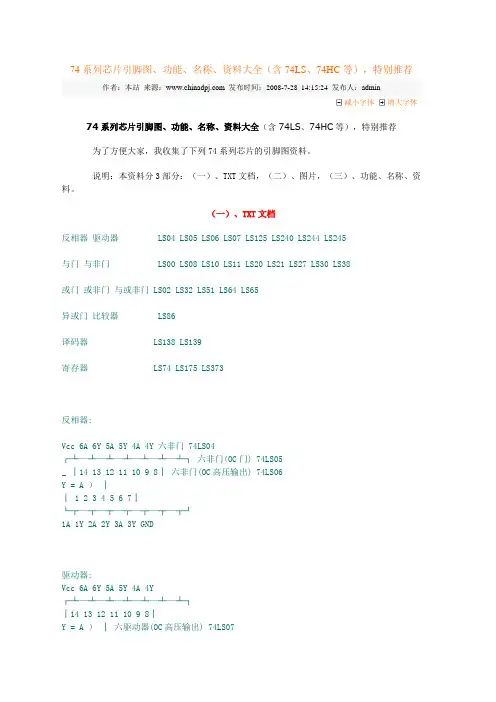
74系列芯片引脚图、功能、名称、资料大全(含74LS、74HC等),特别推荐作者:本站来源: 发布时间:2008-7-28 14:15:24 发布人:admin减小字体增大字体74系列芯片引脚图、功能、名称、资料大全(含74LS、74HC等),特别推荐为了方便大家,我收集了下列74系列芯片的引脚图资料。
说明:本资料分3部分:(一)、TXT文档,(二)、图片,(三)、功能、名称、资料。
(一)、TXT文档反相器驱动器LS04 LS05 LS06 LS07 LS125 LS240 LS244 LS245与门与非门LS00 LS08 LS10 LS11 LS20 LS21 LS27 LS30 LS38或门或非门与或非门 LS02 LS32 LS51 LS64 LS65异或门比较器LS86译码器LS138 LS139寄存器LS74 LS175 LS373反相器:Vcc 6A 6Y 5A 5Y 4A 4Y 六非门 74LS04┌┴—┴—┴—┴—┴—┴—┴┐六非门(OC门) 74LS05_ │14 13 12 11 10 9 8│六非门(OC高压输出) 74LS06Y = A )││ 1 2 3 4 5 6 7│└┬—┬—┬—┬—┬—┬—┬┘1A 1Y 2A 2Y 3A 3Y GND驱动器:Vcc 6A 6Y 5A 5Y 4A 4Y┌┴—┴—┴—┴—┴—┴—┴┐│14 13 12 11 10 9 8│Y = A )│六驱动器(OC高压输出) 74LS07│ 1 2 3 4 5 6 7│└┬—┬—┬—┬—┬—┬—┬┘1A 1Y 2A 2Y 3A 3Y GNDVcc -4C 4A 4Y -3C 3A 3Y┌┴—┴—┴—┴—┴—┴—┴┐_ │14 13 12 11 10 9 8│Y =A+C )│四总线三态门 74LS125│ 1 2 3 4 5 6 7│└┬—┬—┬—┬—┬—┬—┬┘-1C 1A 1Y -2C 2A 2Y GNDVcc -G B1 B2 B3 B4 B8 B6 B7 B8┌┴—┴—┴—┴—┴—┴—┴—┴—┴—┴┐ 8位总线驱动器 74LS245 │20 19 18 17 16 15 14 13 12 11│)│ DIR=1 A=>B│ 1 2 3 4 5 6 7 8 9 10│ DIR=0 B=>A└┬—┬—┬—┬—┬—┬—┬—┬—┬—┬┘DIR A1 A2 A3 A4 A5 A6 A7 A8 GND页首非门,驱动器与门,与非门或门,或非门异或门,比较器译码器寄存器正逻辑与门,与非门:Vcc 4B 4A 4Y 3B 3A 3Y┌┴—┴—┴—┴—┴—┴—┴┐│14 13 12 11 10 9 8│Y = AB )│ 2输入四正与门 74LS08│ 1 2 3 4 5 6 7│└┬—┬—┬—┬—┬—┬—┬┘1A 1B 1Y 2A 2B 2Y GNDVcc 4B 4A 4Y 3B 3A 3Y┌┴—┴—┴—┴—┴—┴—┴┐__ │14 13 12 11 10 9 8│Y = AB )│ 2输入四正与非门 74LS00│ 1 2 3 4 5 6 7│└┬—┬—┬—┬—┬—┬—┬┘1A 1B 1Y 2A 2B 2Y GNDVcc 1C 1Y 3C 3B 3A 3Y┌┴—┴—┴—┴—┴—┴—┴┐___ │14 13 12 11 10 9 8│Y = ABC )│ 3输入三正与非门 74LS10│ 1 2 3 4 5 6 7│└┬—┬—┬—┬—┬—┬—┬┘1A 1B 2A 2B 2C 2Y GNDVcc H G Y┌┴—┴—┴—┴—┴—┴—┴┐│14 13 12 11 10 9 8│)│ 8输入与非门 74LS30│ 1 2 3 4 5 6 7│ ________└┬—┬—┬—┬—┬—┬—┬┘ Y = ABCDEFGHA B C D E F GND页首非门,驱动器与门,与非门或门,或非门异或门,比较器译码器寄存器正逻辑或门,或非门:Vcc 4B 4A 4Y 3B 3A 3Y┌┴—┴—┴—┴—┴—┴—┴┐ 2输入四或门 74LS32│14 13 12 11 10 9 8│)│ Y = A+B│ 1 2 3 4 5 6 7│└┬—┬—┬—┬—┬—┬—┬┘1A 1B 1Y 2A 2B 2Y GNDVcc 4Y 4B 4A 3Y 3B 3A┌┴—┴—┴—┴—┴—┴—┴┐ 2输入四或非门 74LS02│14 13 12 11 10 9 8│ ___)│ Y = A+B│ 1 2 3 4 5 6 7│└┬—┬—┬—┬—┬—┬—┬┘1Y 1A 1B 2Y 2A 2B GNDVcc 2Y 2B 2A 2D 2E 1F┌┴—┴—┴—┴—┴—┴—┴┐双与或非门 74S51│14 13 12 11 10 9 8│ _____)│ 2Y = AB+DE│ 1 2 3 4 5 6 7│ _______└┬—┬—┬—┬—┬—┬—┬┘ 1Y = ABC+DEF1Y 1A 1B 1C 1D 1E GNDVcc D C B K J Y┌┴—┴—┴—┴—┴—┴—┴┐ 4-2-3-2与或非门 74S64 74S65(OC门)│14 13 12 11 10 9 8│ ______________)│ Y = ABCD+EF+GHI+JK│ 1 2 3 4 5 6 7│└┬—┬—┬—┬—┬—┬—┬┘A E F G H I GND页首非门,驱动器与门,与非门或门,或非门异或门,比较器译码器寄存器2输入四异或门 74LS86Vcc 4B 4A 4Y 3Y 3B 3A┌┴—┴—┴—┴—┴—┴—┴┐│14 13 12 11 10 9 8│)│ _ _│ 1 2 3 4 5 6 7│ Y=AB+AB└┬—┬—┬—┬—┬—┬—┬┘1A 1B 1Y 2Y 2A 2B GND8*2输入比较器 74LS688_Vcc Y B8 A8 B7 A7 B6 A6 B5 A5┌┴—┴—┴—┴—┴—┴—┴—┴—┴—┴┐ 8*2输入比较器 74LS688│20 19 18 17 16 15 14 13 12 11│)││ 1 2 3 4 5 6 7 8 9 10│└┬—┬—┬—┬—┬—┬—┬—┬—┬—┬┘CE A1 B1 A2 B2 A3 B3 A4 B4 GND_Y=A1⊙B1+A2⊙B2+A3⊙B3+A4⊙B4+A5⊙B5+A6⊙B6+A7⊙B7+A8⊙B8页首非门,驱动器与门,与非门或门,或非门异或门,比较器译码器寄存器3-8译码器 74LS138Vcc -Y0 -Y1 -Y2 -Y3 -Y4 -Y5 -Y6 __ _ _ _ __ _ _ __ _ _ __ _┌┴—┴—┴—┴—┴—┴—┴—┴┐ Y0=A B C Y1=A B B Y2=A B C Y3=A B C │16 15 14 13 12 11 10 9 │)│ __ _ _ __ _ __ _ __│ 1 2 3 4 5 6 7 8│ Y4=A B C Y5=A B C Y6=A B C Y7=A B C└┬—┬—┬—┬—┬—┬—┬—┬┘A B C -CS0 -CS1 CS2 -Y7 GND双2-4译码器 74LS139Vcc -2G 2A 2B -Y0 -Y1 -Y2 -Y3 __ __ __ __ __ __ __ __┌┴—┴—┴—┴—┴—┴—┴—┴┐ Y0=2A 2B Y1=2A 2B Y2=2A 2B Y3=2A 2B │16 15 14 13 12 11 10 9 │)│ __ __ __ __ __ __ __ __│ 1 2 3 4 5 6 7 8│ Y0=1A 1B Y1=1A 1B Y2=1A 1B Y3=1A 1B└┬—┬—┬—┬—┬—┬—┬—┬┘-1G 1A 1B -Y0 -Y1 -Y2 -Y3 GND8*2输入比较器 74LS688_Vcc Y B8 A8 B7 A7 B6 A6 B5 A5┌┴—┴—┴—┴—┴—┴—┴—┴—┴—┴┐ 8*2输入比较器 74LS688│20 19 18 17 16 15 14 13 12 11│)││ 1 2 3 4 5 6 7 8 9 10│└┬—┬—┬—┬—┬—┬—┬—┬—┬—┬┘CE A1 B1 A2 B2 A3 B3 A4 B4 GND_Y=A1⊙B1+A2⊙B2+A3⊙B3+A4⊙B4+A5⊙B5+A6⊙B6+A7⊙B7+A8⊙B8寄存器:Vcc 2CR 2D 2Ck 2St 2Q -2Q┌┴—┴—┴—┴—┴—┴—┴┐双D触发器74LS74│14 13 12 11 10 9 8 │)││ 1 2 3 4 5 6 7│└┬—┬—┬—┬—┬—┬—┬┘1Cr 1D 1Ck 1St 1Q -1Q GNDVcc 8Q 8D 7D 7Q 6Q 6D 5D 5Q ALE┌┴—┴—┴—┴—┴—┴—┴—┴—┴—┴┐ 8位锁存器 74LS373│20 19 18 17 16 15 14 13 12 11│)││ 1 2 3 4 5 6 7 8 9 10│└┬—┬—┬—┬—┬—┬—┬—┬—┬—┬┘-OE 1Q 1D 2D 2Q 3Q 3D 4D 4Q GND等.(二)、图片(可点击放大,或下载后放大)(三)、功能、名称、资料下面介绍一下常用的74芯片,以便大家在电路中遇到了查询---------------------------------------------------- 型号内容---------------------------------------------------- 74ls00 2输入四与非门74ls01 2输入四与非门 (oc)74ls02 2输入四或非门74ls03 2输入四与非门 (oc)74ls04 六倒相器74ls05 六倒相器(oc)74ls06 六高压输出反相缓冲器/驱动器(oc,30v) 74ls07 六高压输出缓冲器/驱动器(oc,30v)74ls08 2输入四与门74ls09 2输入四与门(oc)74ls10 3输入三与非门74ls11 3输入三与门74ls12 3输入三与非门 (oc)74ls13 4输入双与非门 (斯密特触发)74ls14 六倒相器(斯密特触发)74ls15 3输入三与门 (oc)74ls16 六高压输出反相缓冲器/驱动器(oc,15v) 74ls17 六高压输出缓冲器/驱动器(oc,15v)74ls18 4输入双与非门 (斯密特触发)74ls19 六倒相器(斯密特触发)74ls20 4输入双与非门74ls21 4输入双与门74ls22 4输入双与非门(oc)74ls23 双可扩展的输入或非门74ls24 2输入四与非门(斯密特触发)74ls25 4输入双或非门(有选通)74ls26 2输入四高电平接口与非缓冲器(oc,15v) 74ls27 3输入三或非门74ls28 2输入四或非缓冲器74ls30 8输入与非门74ls31 延迟电路74ls32 2输入四或门74ls33 2输入四或非缓冲器(集电极开路输出) 74ls34 六缓冲器74ls35 六缓冲器(oc)74ls36 2输入四或非门(有选通)74ls37 2输入四与非缓冲器74ls38 2输入四或非缓冲器(集电极开路输出) 74ls39 2输入四或非缓冲器(集电极开路输出) 74ls40 4输入双与非缓冲器74ls41 bcd-十进制计数器74ls42 4线-10线译码器(bcd输入)74ls43 4线-10线译码器(余3码输入)74ls44 4线-10线译码器(余3葛莱码输入)74ls45 bcd-十进制译码器/驱动器74ls46 bcd-七段译码器/驱动器74ls47 bcd-七段译码器/驱动器74ls48 bcd-七段译码器/驱动器74ls49 bcd-七段译码器/驱动器(oc)74ls50 双二路2-2输入与或非门(一门可扩展)74ls51 双二路2-2输入与或非门74ls51 二路3-3输入,二路2-2输入与或非门74ls52 四路2-3-2-2输入与或门(可扩展)74ls53 四路2-2-2-2输入与或非门(可扩展)74ls53 四路2-2-3-2输入与或非门(可扩展)74ls54 四路2-2-2-2输入与或非门74ls54 四路2-3-3-2输入与或非门74ls54 四路2-2-3-2输入与或非门74ls55 二路4-4输入与或非门(可扩展)74ls60 双四输入与扩展74ls61 三3输入与扩展74ls62 四路2-3-3-2输入与或扩展器74ls63 六电流读出接口门74ls64 四路4-2-3-2输入与或非门74ls65 四路4-2-3-2输入与或非门(oc)74ls70 与门输入上升沿jk触发器74ls71 与输入r-s主从触发器74ls72 与门输入主从jk触发器74ls73 双j-k触发器(带清除端)74ls74 正沿触发双d型触发器(带预置端和清除端)74ls75 4位双稳锁存器74ls76 双j-k触发器(带预置端和清除端)74ls77 4位双稳态锁存器74ls78 双j-k触发器(带预置端,公共清除端和公共时钟端) 74ls80 门控全加器74ls81 16位随机存取存储器74ls82 2位二进制全加器(快速进位)74ls83 4位二进制全加器(快速进位)74ls84 16位随机存取存储器74ls85 4位数字比较器74ls86 2输入四异或门74ls87 四位二进制原码/反码/oi单元74ls89 64位读/写存储器74ls90 十进制计数器74ls91 八位移位寄存器74ls92 12分频计数器(2分频和6分频)74ls93 4位二进制计数器74ls94 4位移位寄存器(异步)74ls95 4位移位寄存器(并行io)74ls96 5位移位寄存器74ls97 六位同步二进制比率乘法器74ls100 八位双稳锁存器74ls103 负沿触发双j-k主从触发器(带清除端)74ls106 负沿触发双j-k主从触发器(带预置,清除,时钟) 74ls107 双j-k主从触发器(带清除端)74ls108 双j-k主从触发器(带预置,清除,时钟)74ls109 双j-k触发器(带置位,清除,正触发)74ls110 与门输入j-k主从触发器(带锁定)74ls111 双j-k主从触发器(带数据锁定)74ls112 负沿触发双j-k触发器(带预置端和清除端)74ls113 负沿触发双j-k触发器(带预置端)74ls114 双j-k触发器(带预置端,共清除端和时钟端)74ls116 双四位锁存器74ls120 双脉冲同步器/驱动器74ls121 单稳态触发器(施密特触发)74ls122 可再触发单稳态多谐振荡器(带清除端)74ls123 可再触发双单稳多谐振荡器74ls125 四总线缓冲门(三态输出)74ls126 四总线缓冲门(三态输出)74ls128 2输入四或非线驱动器74ls131 3-8译码器74ls132 2输入四与非门(斯密特触发)74ls133 13输入端与非门74ls134 12输入端与门(三态输出)74ls135 四异或/异或非门74ls136 2输入四异或门(oc)74ls137 八选1锁存译码器/多路转换器74ls138 3-8线译码器/多路转换器74ls139 双2-4线译码器/多路转换器74ls140 双4输入与非线驱动器74ls141 bcd-十进制译码器/驱动器74ls142 计数器/锁存器/译码器/驱动器74ls145 4-10译码器/驱动器74ls147 10线-4线优先编码器74ls148 8线-3线八进制优先编码器74ls150 16选1数据选择器(反补输出)74ls151 8选1数据选择器(互补输出)74ls152 8选1数据选择器多路开关74ls153 双4选1数据选择器/多路选择器74ls154 4线-16线译码器74ls155 双2-4译码器/分配器(图腾柱输出)74ls156 双2-4译码器/分配器(集电极开路输出)74ls157 四2选1数据选择器/多路选择器74ls158 四2选1数据选择器(反相输出)74ls160 可预置bcd计数器(异步清除)74ls161 可预置四位二进制计数器(并清除异步)74ls162 可预置bcd计数器(异步清除)74ls163 可预置四位二进制计数器(并清除异步)74ls164 8位并行输出串行移位寄存器74ls165 并行输入8位移位寄存器(补码输出)74ls166 8位移位寄存器74ls167 同步十进制比率乘法器74ls168 4位加/减同步计数器(十进制)74ls169 同步二进制可逆计数器74ls170 4*4寄存器堆74ls171 四d触发器(带清除端)74ls172 16位寄存器堆74ls173 4位d型寄存器(带清除端)74ls174 六d触发器74ls175 四d触发器74ls176 十进制可预置计数器74ls177 2-8-16进制可预置计数器74ls178 四位通用移位寄存器74ls179 四位通用移位寄存器74ls180 九位奇偶产生/校验器74ls181 算术逻辑单元/功能发生器74ls182 先行进位发生器74ls183 双保留进位全加器74ls184 bcd-二进制转换器74ls185 二进制-bcd转换器74ls190 同步可逆计数器(bcd,二进制)74ls191 同步可逆计数器(bcd,二进制)74ls192 同步可逆计数器(bcd,二进制)74ls193 同步可逆计数器(bcd,二进制)74ls194 四位双向通用移位寄存器74ls195 四位通用移位寄存器74ls196 可预置计数器/锁存器74ls197 可预置计数器/锁存器(二进制)74ls198 八位双向移位寄存器74ls199 八位移位寄存器74ls210 2-5-10进制计数器74ls213 2-n-10可变进制计数器74ls221 双单稳触发器74ls230 八3态总线驱动器74ls231 八3态总线反向驱动器74ls240 八缓冲器/线驱动器/线接收器(反码三态输出) 74ls241 八缓冲器/线驱动器/线接收器(原码三态输出)74ls243 4同相三态总线收发器74ls244 八缓冲器/线驱动器/线接收器74ls245 八双向总线收发器74ls246 4线-七段译码/驱动器(30v)74ls247 4线-七段译码/驱动器(15v)74ls248 4线-七段译码/驱动器74ls249 4线-七段译码/驱动器74ls251 8选1数据选择器(三态输出)74ls253 双四选1数据选择器(三态输出)74ls256 双四位可寻址锁存器74ls257 四2选1数据选择器(三态输出)74ls258 四2选1数据选择器(反码三态输出)74ls259 8为可寻址锁存器74ls260 双5输入或非门74ls261 4*2并行二进制乘法器74ls265 四互补输出元件74ls266 2输入四异或非门(oc)74ls270 2048位rom (512位四字节,oc)74ls271 2048位rom (256位八字节,oc)74ls273 八d触发器74ls274 4*4并行二进制乘法器74ls275 七位片式华莱士树乘法器74ls276 四jk触发器74ls278 四位可级联优先寄存器74ls279 四s-r锁存器74ls280 9位奇数/偶数奇偶发生器/较验器74ls28174ls283 4位二进制全加器74ls290 十进制计数器74ls291 32位可编程模74ls293 4位二进制计数器74ls294 16位可编程模74ls295 四位双向通用移位寄存器74ls298 四-2输入多路转换器(带选通)74ls299 八位通用移位寄存器(三态输出)74ls348 8-3线优先编码器(三态输出)74ls352 双四选1数据选择器/多路转换器74ls353 双4-1线数据选择器(三态输出)74ls354 8输入端多路转换器/数据选择器/寄存器,三态补码输出74ls355 8输入端多路转换器/数据选择器/寄存器,三态补码输出74ls356 8输入端多路转换器/数据选择器/寄存器,三态补码输出74ls357 8输入端多路转换器/数据选择器/寄存器,三态补码输出74ls365 6总线驱动器74ls367 六同向三态缓冲器/线驱动器74ls368 六反向三态缓冲器/线驱动器74ls373 八d锁存器74ls374 八d触发器(三态同相)74ls375 4位双稳态锁存器74ls377 带使能的八d触发器74ls378 六d触发器74ls379 四d触发器74ls381 算术逻辑单元/函数发生器74ls382 算术逻辑单元/函数发生器74ls384 8位*1位补码乘法器74ls385 四串行加法器/乘法器74ls386 2输入四异或门74ls390 双十进制计数器74ls391 双四位二进制计数器74ls395 4位通用移位寄存器74ls396 八位存储寄存器74ls398 四2输入端多路开关(双路输出)74ls399 四-2输入多路转换器(带选通)74ls422 单稳态触发器74ls423 双单稳态触发器74ls440 四3方向总线收发器,集电极开路74ls441 四3方向总线收发器,集电极开路74ls442 四3方向总线收发器,三态输出74ls443 四3方向总线收发器,三态输出74ls444 四3方向总线收发器,三态输出74ls445 bcd-十进制译码器/驱动器,三态输出74ls446 有方向控制的双总线收发器74ls448 四3方向总线收发器,三态输出74ls449 有方向控制的双总线收发器74ls465 八三态线缓冲器74ls466 八三态线反向缓冲器74ls467 八三态线缓冲器74ls468 八三态线反向缓冲器74ls490 双十进制计数器74ls540 八位三态总线缓冲器(反向)74ls541 八位三态总线缓冲器74ls589 有输入锁存的并入串出移位寄存器74ls590 带输出寄存器的8位二进制计数器74ls591 带输出寄存器的8位二进制计数器74ls592 带输出寄存器的8位二进制计数器74ls593 带输出寄存器的8位二进制计数器74ls594 带输出锁存的8位串入并出移位寄存器74ls595 8位输出锁存移位寄存器74ls596 带输出锁存的8位串入并出移位寄存器74ls597 8位输出锁存移位寄存器74ls598 带输入锁存的并入串出移位寄存器74ls599 带输出锁存的8位串入并出移位寄存器74ls604 双8位锁存器74ls605 双8位锁存器74ls606 双8位锁存器74ls607 双8位锁存器74ls620 8位三态总线发送接收器(反相)74ls621 8位总线收发器74ls622 8位总线收发器74ls623 8位总线收发器74ls640 反相总线收发器(三态输出)74ls641 同相8总线收发器,集电极开路74ls642 同相8总线收发器,集电极开路74ls643 8位三态总线发送接收器74ls644 真值反相8总线收发器,集电极开路74ls645 三态同相8总线收发器74ls646 八位总线收发器,寄存器74ls647 八位总线收发器,寄存器74ls648 八位总线收发器,寄存器74ls649 八位总线收发器,寄存器74ls651 三态反相8总线收发器74ls652 三态反相8总线收发器74ls653 反相8总线收发器,集电极开路74ls654 同相8总线收发器,集电极开路74ls668 4位同步加/减十进制计数器74ls669 带先行进位的4位同步二进制可逆计数器74ls670 4*4寄存器堆(三态)74ls671 带输出寄存的四位并入并出移位寄存器74ls672 带输出寄存的四位并入并出移位寄存器74ls673 16位并行输出存储器,16位串入串出移位寄存器74ls674 16位并行输入串行输出移位寄存器74ls681 4位并行二进制累加器74ls682 8位数值比较器(图腾柱输出)74ls683 8位数值比较器(集电极开路)74ls684 8位数值比较器(图腾柱输出)74ls685 8位数值比较器(集电极开路)74ls686 8位数值比较器(图腾柱输出)74ls687 8位数值比较器(集电极开路)74ls688 8位数字比较器(oc输出)74ls689 8位数字比较器74ls690 同步十进制计数器/寄存器(带数选,三态输出,直接清除)74ls691 计数器/寄存器(带多转换,三态输出)74ls692 同步十进制计数器(带预置输入,同步清除)74ls693 计数器/寄存器(带多转换,三态输出)74ls696 同步加/减十进制计数器/寄存器(带数选,三态输出,直接清除)74ls697 计数器/寄存器(带多转换,三态输出)74ls698 计数器/寄存器(带多转换,三态输出)74ls699 计数器/寄存器(带多转换,三态输出)74ls716 可编程模n十进制计数器74ls718 可编程模n十进制计数器[本站(中国单片机网),摘自/chip/167.html作者,如还有需要请上电子论坛/bbs/]。

Communicative linear actuator fail-safe and extended functionalities for adjusting dampers and slide valves in technical building installations and in laboratories• Air damper size up to approx. 3 m²• Actuating force 450 N• Nominal voltage AC/DC 24 V• Control modulating, communicative 2...10 V variable• Position feedback 2...10 V variable • Length of Stroke Max. 100 mm, adjustable in 20 mm increments • Conversion of sensor signals•Communication via Belimo MP-BusTechnical dataElectrical dataNominal voltageAC/DC 24 V Nominal voltage frequency 50/60 HzNominal voltage rangeAC 19.2...28.8 V / DC 21.6...28.8 V Power consumption in operation 11 W Power consumption in rest position 3 W Power consumption for wire sizing21 VAPower consumption for wire sizing note Imax 20 A @ 5 msConnection supply / control Cable 1 m, 4 x 0.75 mm²Parallel operation Yes (note the performance data)Functional dataActuating force motor 450 N Communicative control MP-Bus Operating range Y 2...10 V Input Impedance100 kΩOptions positioning signalOpen/close3-point (AC only)Modulating (DC 0...32 V) Operating range Y variableStart point 0.5...30 V End point 2.5...32 V Position feedback U2...10 VPosition feedback U note Max. 0.5 mAPosition feedback U variable Start point 0.5...8 V End point 2.5...10 VSetting fail-safe position 0...100%, adjustable in increments of 10%(POP rotary knob on 0 corresponds to retracted gear rod) Bridging time (PF)2 s Bridging time (PF) variable 0...10 s Position accuracy±5%Direction of motion motor selectable with switchDirection of motion note Y = 0 V: with switch 0 (retracted) / 1 (extended) Direction of motion variable electronically reversibleDirection of motion fail-safe selectable with switch 0...100% (retracted 0%) Manual override with push-button Stroke100 mmLength of Stroke Max. 100 mm, adjustable in 20 mm increments Stroke limitationcan be limited on both sides with mechanical end stopsRunning time motor120 s / 100 mm Running time motor variable 90...150 s / 100 mm Running time fail-safe35 s / 100 mm Running time fail-safe note <35 s @ 0...50°C Adaptation setting rangemanualAdaptation setting range variableNo actionAdaptation when switched onAdaptation after pushing the gear disengagement buttonOverride controlMAX (maximum position) = 100%MIN (minimum position) = 0%ZS (intermediate position, AC only) = 50%P ro du ct nol on ge r a v a i l ab l eFunctional dataOverride control variable MAX = (MIN + 5%)...100%MIN = 0%...(MAX – 5%)ZS = MIN...MAX Sound power level, motor 52 dB(A)Sound power level, fail-safe 61 dB(A)SafetyProtection class IEC/EN III Safety Extra-Low Voltage (SELV) Protection class ULUL Class 2 Supply Degree of protection IEC/EN IP54 Degree of protection NEMA/UL NEMA 2Enclosure UL Enclosure Type 2EMCCE according to 2014/30/EUCertification IEC/EN IEC/EN 60730-1 and IEC/EN 60730-2-14Certification UL cULus according to UL60730-1A, UL60730-2-14 and CAN/CSA E60730-1:02Certification UL noteThe UL marking on the actuator depends on the production site, the device is UL-compliant in any case Mode of operationType 1.AA Rated impulse voltage supply / control 0.8 kV Control pollution degree 3Ambient temperature -30...50°C Storage temperature -40...80°CAmbient humidity Max. 95% r.H., non-condensingServicing maintenance-free Weight Weight 1.6 kgTermsAbbreviationsPOP = Power off position / fail-safe position PF = Power fail delay time / bridging timeLinear actuator fail-safe, modulating, communicative, AC/DC 24 V, 450 N, Communication via Belimo MP-BusTechnical dataP ro du ct nol on ge r a v a i l ab l e!• The device must not be used outside the specified field of application, especially not in aircraft or in any other airborne means of transport.• Outdoor application: only possible in case that no (sea) water, snow, ice, insolation or aggressive gases interfere directly with the actuator and that is ensured that the ambient conditions remain at any time within the thresholds according to the data sheet.• Only authorised specialists may carry out installation. All applicable legal or institutional installation regulations must be complied during installation.• The device may only be opened at the manufacturer’s site. It does not contain any parts that can be replaced or repaired by the user.• Cables must not be removed from the device.• The rotary supports and coupling pieces available as accessories and must always be used if transverse forces are likely. In addition, the actuator must not be tightly bolted to the application. It must remain movable via the rotary support (refer to «Assembly notes»).• If a rotary support and/or coupling piece is used, actuation force losses are to be expected.• If the actuator is exposed to severely contaminated ambient air, appropriateprecautions must be taken on the system side. Excessive deposits of dust, soot etc. can prevent the gear rod from being extended and retracted correctly.• If not installed horizontally, the gear disengagement push-button may only be actuated when there is no pressure on the gear rod.• To calculate the actuating force required for air dampers and slide valves, thespecifications supplied by the damper manufacturers concerning the cross section, the design, the installation site and the ventilation conditions must be observed.• Self-adaptation is necessary when the system is commissioned or whenever the stroke limiting is adjusted (press the adaptation push-button).• The device contains electrical and electronic components and must not be disposed of as household refuse. All locally valid regulations and requirements must be observed.Product featuresMode of operationThe actuator moves the damper to the desired operating position at the same time as the integrated capacitors are charged. Interrupting the supply voltage causes the damper to be rotated back into the fail-safe position by means of stored electrical energy.Conventional operation:The actuator is connected with a standard modulating signal of 0...10 V and drives to the position defined by the positioning signal. Measuring voltage U serves for the electrical display of the damper position 0.5...100% and as a slave control signal for other actuators.Operation on Bus:The actuator receives its digital positioning signal from the higher level controller via the MP-Bus and drives to the position defined. Connection U serves as communication interface and does not supply an analogue measuring voltage.Linear actuator fail-safe, modulating, communicative, AC/DC 24 V, 450 N, Communication via Belimo MP-BusSafety notesP ro du ct nol on ge r a v a i l ab l ePre-charging time (start up)The capacitor actuators require a pre-charging time. This time is used for charging the capacitors up to a usable voltage level. This ensures that, in the event of a power failure, the actuator can move at any time from its current position into the preset fail-safe position.The duration of the pre-charging time depends mainly on following factors:– Duration of the power failure – PF delay time (bridging time)[d] = Electricity interruption in days [s] = Pre-charging time in secondsPF[s] = Bridging timeCalculation example: Given an electricityinterruption of 7 days and a bridging time (PF) set at 2 s, the actuator requires a pre-charging time of 18 s after the electricity has been reconnected (seegraphic).07≥20211182310162529[d]PF [s]Delivery condition (capacitors)The actuator is completely discharged after delivery from the factory, which is why the actuator requires approximately 20 s pre-charging time before initial commissioning in order to bring the capacitors up to the required voltage level.Converter for sensorsConnection option for a sensor (passive or active sensor or switching contact). The MP actuator serves as an analogue/digital converter for the transmission of the sensor signal via MP-Bus to the higher level system.Parametrisable actuators The factory settings cover the most common applications. Single parameters can be modified with the Belimo Service Tools MFT-P or ZTH EU.Simple direct mountingThe actuator can be directly connected with the application using the enclosed screws. The head of the gear rod is connected to the moving part of the ventilating application individually on the mounting side or with the Z-KS1 coupling piece provided for this purpose.Manual overrideManual control with push-button possible - temporary. The gear is disengaged and the actuator decoupled for as long as the button is pressed.Adjustable strokeIf a stroke limitation will be adjusted, the operating range on this side of the gear rod can be used starting with an extension length of 20 mm and then can be limited respectively in increments of 20 mm by means of the mechanical end stops Z-AS1.High functional reliabilityThe actuator is overload protected, requires no limit switches and automatically stops when the end stop is reached.Home positionThe first time the supply voltage is switched on, i.e. at the time of commissioning, the actuator carries out a synchronisation. The synchronisation is in the home position (0%).The actuator then moves into the position defined by the positioning signal.Setting direction of strokeWhen actuated, the stroke direction switch changes the running direction in normal operation. The stroke direction switch has no influence on the fail-safe position which has been set.P ro du ct nol on ge r a l eSetting fail-safe position (POP)The rotary knob fail-safe position can be used to adjust the desired fail-safe position 0...100% in 10% increments. The rotary knob only refers to the adapted stroke range 30...100mm. No set min or max values are observed. In the event of a power failure, the actuator will move into the selected fail-safe position, taking into account the bridging time which was set.Settings: The rotary knob must be set to the «Tool» position for retroactive settings of the fail-safe position with the Belimo service tool MFT-P. Once the rotary knob is set back to the range 0…100%, the manually set value will have positioning authority.Bridging timeElectrical interruptions can be bridged up to a maximum of 10 s.In the event of a power failure, the actuator will remain stationary in accordance with the set bridging time. If the power failure is greater than the set bridging time, then the actuator will move into the selected fail-safe position.The bridging time set ex-works is 2 s. This can be modified on site in operation with the use of the Belimo service tool MFT-P.Settings: The rotary knob must not be set to the “Tool” position!For retroactive adjustments of the bridging time with the Belimo service tool MFT-P or with the ZTH EU adjustment and diagnostic device only the values need to be entered.Adaption and synchronisationAn adaption can be triggered manually by pressing the “Adaption” button or with the PC-Tool. Both mechanical end stops are detected during the adaption (entire setting range).A range of settings can be adapted using the PC-Tool (see MFT-P documentation)AccessoriesDescriptionType GatewaysGateway MP to Modbus RTU UK24MOD Gateway MP zu BACnet MS/TP UK24BAC Gateway MP to LonWorks UK24LONGateway MP to KNXUK24EIB DescriptionType Electrical accessoriesSignal converter voltage/current 100 kΩ Supply AC/DC 24 V Z-UIC Range controller for wall mounting SBG24 Positioner for wall mounting SGA24 Positioner for built-in mounting SGE24 Positioner for front-panel mounting SGF24 Positioner for wall mountingCRP24-B1Connection cable 5 m, A: RJ11 6/4 ZTH EU, B: 6-pin service socket for Belimo deviceZK1-GEN Connection cable 5 m, A: RJ11 6/4 ZTH EU, B: free wire end for connection to MP/PP terminalZK2-GEN Connecting board MP-Bus for wiring boxes EXT-WR-FP..-MP ZFP2-MPMP-Bus power supply for MP actuators ZN230-24MPDescriptionType Mechanical accessoriesEnd stop kit, Multipack 20 pcs.Z-AS1 Rotary support, for linear actuator Z-DS1Coupling piece M8Z-KS1DescriptionType Service ToolsService Tool, with ZIP-USB functionZTH EU Belimo PC-Tool, Software for adjustments and diagnostics MFT-PAdapter for Service-Tool ZTHMFT-CElectrical installation!Notes• Connection via safety isolating transformer.• Parallel connection of other actuators possible. Observe the performance data.P ro du ct nol on ge r a v a i l ab l eWiring diagramsAC/DC 24 V, modulatingOperation on the MP-BusT~VVCable colours:1 = black2 = red3 = white5 = orange T~Cable colours:1 = black2 = red3 = white5 = orangeFunctionsFunctions when operated on MP-BusConnection on the MP-Bus MP-Bus Network topologyTA) more actuators and sensors(max.8)There are no restrictions for thenetwork topology (star, ring, tree ormixed forms are permitted).Supply and communication in oneand the same 3-wire cable• no shielding or twisting necessary• no terminating resistors required Connection of active sensors Connection of external switching contactTA) more actuators and sensors(max.8)• Supply AC/DC 24 V• Output signal DC 0...10 V(max. DC 0...32 V)• Resolution 30 mVA) more actuators and sensors(max.8)• Switching current 16 mA @ 24 V• Start point of the operating rangemust be parameterised on the MPactuator as ≥ 0.5 VConnection of passive sensorsTNi1000PT1000NTC–28...+98°C–35...+155°C–10...+160°C 1)850...1600 Ω 2)850...1600 Ω 2)200 Ω...60 kΩ 2)A) more actuators and sensors(max.8)1) Depending on the type2) Resolution 1 OhmLinear actuator fail-safe, modulating, communicative, AC/DC 24 V, 450 N, Communication via Belimo MP-BusElectrical installationroctnoloilableFunctions with basic values (conventional mode)Override control with AC 24 V with relay contactsOverride control with AC 24 V with rotary switchab c0%ZS 50% 100% Y)Control remotely 0...100% with positioner SG..Minimum limit with positioner SG..T%]Follow-up control (position-dependent)Control with 4...20 mA via external resistorT ~ V VmA VTCaution:The operating range must be set to DC 2...10 V.The 500 Ω resistor converts the4...20 mA current signal to a voltage signal DC 2...10 VFunctional check1325–+T~UY Procedure1. Apply 24 V to connection 1 and 22. Disconnect connection 3:- for direction of stroke 0: Actuator travels in the direction “retracted” - for direction of stroke 1: Actuator travels in the direction “extended”3. Short circuit connections 2 and 3: - Actuator runs in the opposite directionP ro du ogi l ab l eFunctions for devices with specific parameters (Parametrisation necessary)Override control and limiting with AC 24 V with relay contacts Override control and limiting with AC 24 V with rotary switch))1) Caution: This function is onlyguaranteed if the start point of theoperating range is defined as min.0.5 V.Control open/close Control 3-pointT~ProductnolongvailableStatus Address 100.10.50.9TOOLPower AdaptionPOP 67234895011Direction of stroke switch Cover, POP button POP buttonScale for manual adjustment Position for adjustment with tool Tool socketDisengagement button Press button: Acknowledgment of addressingPress button: Triggers stroke adaption, followed by standard operationLinear actuator fail-safe, modulating, communicative, AC/DC 24 V, 450 N, Communication via Belimo MP-BusOperating controls and indicatorsP ro da!Notes• If a rotary support and/or coupling piece is used, losses in the actuation force losses are to be expected.Applications without transverse forceThe linear actuator is screwed directly to the housing at three points. Afterwards, the head of the gear rod is fastened to the moving part of the ventilation application (e.g. damper or slide valve).Applications with transverse forcesThe coupling piece with the internal thread (Z-KS1) is connected to the head of the gear rod. The rotary support (Z-DS1) is screwed to the ventilation application. Afterwards, the linear actuator is screwed to the previously mounted rotary support with the enclosed screw. Afterwards, the coupling piece, which is mounted to the head of the gear rod, is attached to the moving part of the ventilating application (e.g. damper or slide valve). The transverse forces can be compensated for to a certain limit with the rotary support and/or coupling piece. The maximum permissible swivel angle of the rotary support and coupling piece is 10° (angle), laterally and upwards.Stroke limitationIf the stroke limitations are used on the gear rod, the mechanical operating range on this side of the gear rod can be used starting with an extension length of 20 mm.ServiceService Tools connectionThe actuator can be parametrised by ZTH EU via the service socket.For an extended parametrisation the PC tool can be connected.Connection ZTH EU / PC-ToolAC 24 VT~Linear actuator fail-safe, modulating, communicative, AC/DC 24 V, 450 N, Communication via Belimo MP-BusInstallation notesP ro du ct na v a i l ab l eDimensional drawings81233.510036141190419994Further documentation• Overview MP Cooperation Partners• Tool connections• Introduction to MP-Bus TechnologyLinear actuator fail-safe, modulating, communicative, AC/DC 24 V, 450 N, Communication via Belimo MP-BusDimensions [mm]SHK24A-MP100 • en-gb • 2020-01-13 • subject to changes11P ro du ct nol on ge r a v a i l ab l e。