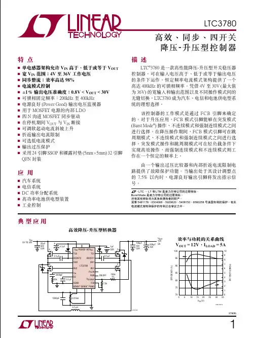
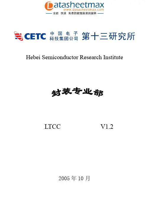
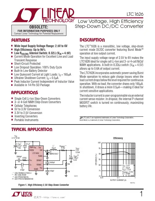
132201fbT YPICAL APPLICATIONF EATURESA PPLICATIONSD ESCRIPTION 18-Channel LED DriverThe L TC3220/L TC3220-1 are highly integrated multi-display LED drivers. These parts contain a high effi ciency, low noise charge pump to provide power to up to eighteen universal LED current sources. The L TC3220/L TC3220-1 require only fi ve small ceramic capacitors to form a complete LED power supply and current controller .The LED currents are set by an internal precision cur-rent reference. Independent dimming, on/off, blinking and gradation control for all universal current sources is achieved via the I 2C serial interface. 6-bit linear DACs are available to adjust brightness levels independently for each universal LED current source.The L TC3220/L TC3220-1 charge pump optimizes effi ciency based on the voltage across the LED current sources. The part powers up in 1x mode and will automatically switch to boost mode whenever any enabled LED current source begins to enter dropout. The fi rst dropout switches the parts into 1.5x mode and a subsequent dropout switches the L TC3220/L TC3220-1 into 2x mode. The parts reset to 1x mode whenever a data bit is updated via the I 2C port.nEighteen 20mA Universal Current Sources with 64-Step Linear Brightness Controln Independent On/Off, Brightness Level, Blinking and Gradation Control for Each Current Source Using 2-Wire I 2C Interfacen Low Noise Multi-Mode Charge Pump (1x, 1.5x, 2x) Provides Up to 91% Effi ciencyn Slew Limited Switching Reduces Conducted and Radiated Noise (EMI)n Up to 360mA Total Output Current n Internal Current Referencen Single Reset Pin for Asynchronous Shutdown and Reset of All Data Registers n T wo I 2C Addresses Are Available (L TC3220: 0011100, L TC3220-1: 0011101)n Automatic or Forced Mode Switching n Internal Soft-Start Limits Inrush Current n Short-Circuit/Thermal Protection n 4mm × 4mm Ultrathin (0.55mm) 28-Lead QFN PackagenVideo Phones with QVGA+ Displays n Keypad Lightingn General/Miscellaneous LightingL , L T , L TC and L TM are registered trademarks of Linear Technology Corporation. All other trademarks are the property of their respective owners. Protected by U.S. Patents including 6411531.DVI C2C36-LED Main, 4 RGB LEDs232201fbP IN CONFIGURATIONA BSOLUTE MAXIMUM RATINGS V IN , DV CC , CPO to GND ................................–0.3V to 6V ULED1-ULED18 to GND ...............................–0.3V to 6V SDA, SCL, RST ............................–0.3V to (DV CC + 0.3V)I CPO (Continuous) (Note 2) ..................................360mA I ULED1-18 (Note 2) ..................................................25mA CPO Short-Circuit Duration ..............................Indefi nite Operating Temperature Range (Note 3)L TC3220E/L TC3220E-1 ........................–40°C to 85°C L TC3220I/L TC3220I-1 ........................–40°C to 125°C Storage Temperature Range ...................–65°C to 150°C(Notes 1, 4)28272625242389TOP VIEW29PF PACKAGE28-LEAD UTQFN (4mm s 4mm)1011121314ULED1ULED2ULED3ULED4ULED5ULED6ULED7ULED18ULED17ULED16ULED15ULED14ULED13ULED12C P OC 1PC 2PR S TV I NC 1MC 2MU L E D 8U L E D 9D V C CS C LS D A U L E D 10U L E D 1116151718192021675432122T JMAX = 125°C, θJA = 37°C/WEXPOSED PAD (PIN 29) IS GND, MUST BE SOLDERED TO PCBORDER INFORMATIONLEAD FREE FINISH TAPE AND REEL PART MARKING *PACKAGE DESCRIPTION TEMPERATURE RANGE L TC3220EPF#PBF L TC3220EPF#TRPBF 3220T 28-Lead UTQFN (4mm × 4mm)–40°C to 85°C L TC3220EPF-1#PBF L TC3220EPF-1#TRPBF 2201T 28-Lead UTQFN (4mm × 4mm)–40°C to 85°C L TC3220IPF#PBF L TC3220IPF#TRPBF 3220T 28-Lead UTQFN (4mm × 4mm)–40°C to 125°C L TC3220IPF-1#PBFL TC3220IPF-1#TRPBF2201T28-Lead UTQFN (4mm × 4mm)–40°C to 125°CConsult L TC Marketing for parts specifi ed with wider operating temperature ranges. *The temperature grade is identifi ed by a label on the shipping container .Consult L TC Marketing for information on non-standard lead based fi nish parts.For more information on lead free part marking, go to: http://www.linear .com/leadfree/ For more information on tape and reel specifi cations, go to: http://www.linear .com/tapeandreel/E LECTRICAL CHARACTERISTICS SYMBOLPARAMETERCONDITIONSMINTYP MAX UNITSV IN Operating Voltage l2.95.5V I VIN Operating Current I CPO = 0, 1x Mode I CPO = 0, 1.5x Mode I CPO = 0, 2x Mode5802.43.2μA mA mA DV CC UVLO Threshold 1V DV CC Operating Voltage l1.55.5V V IN UVLO Threshold1.5VThe l denotes the specifi cations which apply over the full operating temperature range, otherwise specifi cations are at T A = 25°C. V IN = 3.6V , DV CC = 3V , RST = high, C1 = C2 = C3 = 2.2μF , C4 = 4.7μF , unless otherwise noted.E LECTRICAL CHARACTERISTICSThel denotes the specifi cations which apply over the full operating temperature range, otherwise specifi cations are at T A = 25°C. V IN = 3.6V, DV CC = 3V, RST = high, C1 = C2 = C3 = 2.2μF, C4 = 4.7μF, unless otherwise noted.SYMBOL PARAMETER CONDITIONS MIN TYP MAX UNITS V IN Shutdown Current l 3.27μADV CC Shutdown Current l1μA Universal LED Current, 6-Bit Linear DACs, ULED = 1VFull-Scale LED Current l182022mAMinimum (I LSB) LED Current Step0.314mAMinimum Programmable Current ULED Data Register Programmed to0b000000010.395mALED Current Matching Any T wo Outputs, 50% of FS 1.5%LED Dropout Voltage I LED = FS120mVBlink Rate Period REG19, D3 and D4 1.252.5Sec SecULED Up/Down Gradation Ramp Times REG19, D1 and D20.240.480.96Sec Sec SecGradation Period REG19, D1 and D20.3130.6251.250.4100.8201.640SecSecSecV OL General Purpose Output Mode (GPO)I OUT = 1mA, Single Output Enabled5mVLED Turn-On Delay From Stop Bit, Part Enabled4μs Charge Pump (CPO)1x Mode Output Impedance0.6Ω1.5x Mode Output Impedance V IN = 3V, V CPO = 4.2V (Note 5) 3.6Ω2x Mode Output Impedance V IN = 3V, V CPO = 4.8V (Note 5) 4.1ΩCPO Regulation Voltage 1.5x Mode, I CPO = 20mA2x Mode, I CPO = 20mA 4.55.03VVClock Frequency l0.650.85 1.05MHz CPO Short-Circuit DetectionThreshold Voltage l0.4 1.3VTest Current CPO = 0V l1030mA SDA, SCL, RSTV IL l0.3 • DV CC V V IH l0.7 • DV CC V I IH SDA, SCL, RST = DV CC l–11μA I IL SDA, SCL, RST = 0V l–11μA V OL Digital Output Low (SDA)I PULLUP = 3mA l0.120.4V RST Timing Reset Pulse Duration10ns Serial Port Timing (Notes 6, 7)f SCL Clock Operating Frequency400kHz t BUF Bus Free Time Between Stop and StartCondition1.3μs t HD,STA Hold Time After (Repeated) Start Condition0.6μs t SU,STA Repeated Start Condition Setup Time0.6μs t SU,STO Stop Condition Setup Time0.6μs332201fb432201fbT YPICAL PERFORMANCE CHARACTERISTICS Mode Switch Dropout Times1.5x Mode CPO Ripple2x Mode CPO RippleNote 1: Stresses beyond those listed under Absolute Maximum Ratings may cause permanent damage to the device. Exposure to any Absolute Maximum Rating condition for extended periods may affect device reliability and lifetime.Note 2: Based on long term current density limitations.Note 3: The L TC3220E/L TC3220E-1 are guaranteed to meet performance specifi cations from 0°C to 85°C. Specifi cations over the –40°C to 85°C operating temperature range are assured by design, characterization and correlation with statistical process controls. The L TC3220I/L TC3220I-1 are guaranteed to meet performance specifi cations over the full –40°C to 125°C operating temperature range.T A = 25°C unless otherwise noted.Note 4: These devices include overtemperature protection that is intended to protect the devices during momentary overload conditions. Junction temperatures will exceed 125°C when overtemperature protection is active. Continuous operation above the specifi ed maximum operating junction temperature may result in device degradation or failure.Note 5: 1.5x mode output impedance is defi ned as (1.5V IN – V CPO )/I OUT . 2x mode output impedance is defi ned as (2V IN – V CPO )/I OUT .Note 6: All values are referenced to V IH and V IL levels.Note 7: Guaranteed by design.V CPO 1V/DIVV IN = 3.6V250μs/DIV3220 G011s1.5s2sV CPO20mV/DIV AC COUPLEDV IN = 3.6V I CPO = 200mA C CPO = 4.7μF500ns/DIV3220 G02V CPO 20mV/DIV AC COUPLEDV IN = 3.6V I CPO = 200mA C CPO = 4.7μF500ns/DIV3220 G03E LECTRICAL CHARACTERISTICS The l denotes the specifi cations which apply over the full operatingtemperature range, otherwise specifi cations are at T A = 25°C. V IN = 3.6V , DV CC = 3V , RST = high, C1 = C2 = C3 = 2.2μF, C4 = 4.7μF , unless otherwise noted.SYMBOL PARAMETER CONDITIONSMIN TYPMAX UNITSt HD,DAT(OUT)Data Hold Time0900ns t HD,DAT(IN)Input Data Hold Time 0ns t SU,DAT Data Setup Time 100ns t LOW Clock Low Period 1.3μs t HIGH Clock High Period 0.6μs t f Clock Data Fall Time 20300ns t r Clock Data Rise Time 20300ns t SPSpike Supression Time50ns532201fb1x Mode Switch Resistancevs Temperature1.5x Mode Charge Pump Open-Loop Output Resistance vs Temperature1.5x Mode CPO Voltage vs I CPO2x Mode Charge Pump Open-Loop Output Resistance vs Temperature2x Mode CPO Voltage vs I CPOOscillator Frequency vs V IN VoltageV IN Shutdown Current vs V IN VoltageDV CC Current vs DV CC VoltageT YPICAL PERFORMANCE CHARACTERISTICS T A = 25°C unless otherwise noted.TEMPERATURE (°C)–40S W I T C H R E S I S T A N C E (Ω)0.450.500.5551253220 G040.400.350.30–25–102035506580951100.600.650.700.750.80TEMPERATURE (°C)–402.5O P E N -L O O P O U T P U T R E S I S T A N C E (Ω)2.72.93.13.33.53.94.14.34.5–25–1056520355080951103220 G05125I CPO (mA)03.6C P O V O L T A G E (V )3.84.04.24.44.8601201802403220 G063003604.6TEMPERATURE (°C)–403.94.14.34.54.74.9953220 G073.73.5–25–10352055065801101253.33.12.9O P E N -L O O P O U T P U T R E S I S T A N C E (Ω)I CPO (mA)4.2C P O V O L T AG E (V )4.44.64.8601201802403220 G083005.05.24.34.54.74.95.1360V IN VOLTAGE (V)2.9F R E Q U EN C Y (k H z )770780790 5.53220 G09760750730 3.55 4.2 4.85740810800VOLTAGE (V)2.91.5V I N S H U T DO W N C U R R E N T (μA )2.53.54.55.56.57.5 3.554.24.855.53220 G101x Mode No Load V IN Current vs V INVoltageDV CC VOLTAGE (V)1.5D V C C C U R RE N T (μA )0.51.01.52.02.53.0 2.53.54.55.53220 G11V IN VOLTAGE (V)2.9580V I N C U R R E N T (μA )585590595600605610 3.554.2 4.855.53220 G12632201fbP IN FUNCTIONST YPICAL PERFORMANCE CHARACTERISTICS T A = 25°C unless otherwise noted.18-LED ULED Display Effi ciency vs V IN VoltageULED1-ULED18 (Pins 1-9,13-21): Current Source Outputs for Driving LEDs. The LED current can be set from 0mA to 20mA in 64 steps via software control and internal 6-bit linear DAC. Each output can be disabled by setting the associated data register REG1 to REG18 low. ULED1 to ULED18 can also be used as I 2C controlled open-drain general purpose outputs. Connect unused outputs to ground.DV CC (Pin 10): Supply Voltage for All digital I/O lines. This pin sets the logic reference level of the L TC3220/L TC3220-1. DV CC will reset the data registers when set below the undervoltage lockout threshold. A 0.1μF X5R or X7R ceramic capacitor should be connected to ground.SCL (Pin 11): I 2C Clock Input. The logic level for SCL is referenced to DV CC .ULED Current vs Input CodeINPUT CODE (HEX)09U L E D C U R R E N T (m A )102512242D3220 G16520151B 363FV IN VOL TAGE (V)2.9U L E D E F F I C I E N C Y (P L E D /P I N ) (%)10010907050308060402004.5253.8755.1753220 G175.54.23.55 4.853.2251.5x Mode V IN Current vs I CPO(I VIN – 1.5I CPO )2x Mode V IN Current vs I CPO (I VIN – 2I CPO )ULED Pin Current vs ULED Pin VoltageI CPO (mA)V I N C U R R E N T (m A )68101803003220 G1342060120240121416360I CPO (mA)141210864201803003220 G1460120240360V I N C U R R E N T (m A )ULED PIN VOLTAGE (V)U L E D P I N C U R R E N T (m A )10150.23220 G1550.050.10.152520732201fbPIN FUNCTIONSBLOCK DIAGRAMSDA (Pin 12): Input Data for the Serial Port. Serial data is shifted in one bit per clock cycle to control the L TC3220/L TC3220-1. The logic level is referenced to DV CC .C1P , C2P , C1M, C2M (Pins 27, 26, 23, 22): Charge Pump Flying Capacitor Pins. A 2.2μF X7R or X5R ceramic ca-pacitor should be connected from C1P to C1M and C2P to C2M.V IN (Pin 24): Supply Voltage for the Entire Device. This pin must be bypassed with a single 2.2μF low ESR ceramic capacitor .RST (Pin 25): Active Low Reset Input. RST Resets all internal registers and forces L TC3220/L TC3220-1 into shutdown mode.CPO (Pin 28): Output of the Charge Pump. Used to power all LEDs. A 4.7μF X5R or X7R ceramic capacitor should be connected to ground.Exposed Pad (Pin 29): Ground. The Exposed Pad must be soldered to PCB ground.832201fbO PERATION Power ManagementThe L TC3220/L TC3220-1 use a switched capacitor charge pump to boost CPO as much as 2 times the input voltage up to 5.1V . The part starts up in 1x mode. In this mode, V IN is connected directly to CPO. This mode provides maximum effi ciency and minimum noise. The L TC3220/L TC3220-1 will remain in 1x mode until an LED current source drops out. Dropout occurs when a current source voltage becomes too low for the programmed current to be supplied. When dropout is detected, the L TC3220/L TC3220-1 will switch into 1.5x mode. The CPO voltage will then start to increase and will attempt to reach 1.5× V IN up to 4.6V . Any subsequent dropout will cause the part to enter the 2x mode. The CPO voltage will attempt to reach 2× V IN up to 5.1V .A 2-phase non-overlapping clock activates the charge pump switches. In the 2x mode the fl ying capacitors are charged on alternate clock phases from V IN to minimize CPO voltage ripple. In 1.5x mode the fl ying capacitors are charged in series during the fi rst clock phase and stacked in parallel on V IN during the second phase. This sequence of charging and discharging the fl ying capacitors continues at a constant frequency of 850kHz.The current delivered by each LED current source is con-trolled by an associated DAC. Each DAC is programmed via the I 2C port.Figure 1. Charge Pump Open-Loop Thevenin Equivalent CircuitSoft-StartInitially, when the part is in shutdown, a weak switch connects V IN to CPO. This allows V IN to slowly charge the CPO output capacitor and prevent large charging currents from occurring.The L TC3220/L TC3220-1 also employ a soft-start feature on the charge pump to prevent excessive inrush current and supply droop when switching into the step-up modes. The current available to the CPO pin is increased linearly over a typical period of 125μs. Soft-start occurs at the start of both 1.5x and 2x mode changes.Charge Pump StrengthWhen the L TC3220/L TC3220-1 operate in either 1.5x mode or 2x mode, the charge pump can be modeled as a Theve-nin-equivalent circuit to determine the amount of current available from the effective input voltage and effective open-loop output resistance, R OL (Figure 1).R OL is dependent on a number of factors including the switching term, 1/(2f OSC • C FL Y ), internal switch resis-tances and the non-overlap period of the switching circuit. However , for a given R OL , the amount of current available will be directly proportional to the advantage voltage of 1.5V IN – CPO for 1.5x mode and 2V IN – CPO for 2x mode. Consider the example of driving LEDs from a 3.1V supply.O PERATIONIf the LED forward voltage is 3.8V and the current sources require 100mV, the advantage voltage for 1.5x mode is 3.1V • 1.5 – 3.8V – 0.1V or 750mV. Notice that if the input voltage is raised to 3.2V, the advantage voltage jumps to 900mV, a 20% improvement in available strength.F rom F igure 1, for 1.5x mode the available current is given by:I OUT=1.5V IN−V CPOR OL(1)For 2x mode, the available current is given by:I OUT=2V IN−V CPOR OL(2)Notice that the advantage voltage in this case is 3.1V • 2 – 3.8V – 0.1V = 2.3V. R OL is higher in 2x mode but a sig-nifi cant overall increase in available current is achieved. Mode SwitchingThe LTC3220/LTC3220-1 will automatically switch from 1x mode to 1.5x mode and subsequently to 2x mode whenever a dropout condition is detected at an LED pin. Dropout occurs when a current source voltage becomes too low for the programmed current to be supplied. The mode change will not occur unless dropout exists for ap-proximately 400μs.The mode will automatically switch back to 1x whenever a register is updated via the I2C port, when gradation completes ramping down and after each blink period. The parts can be forced to operate in 1x, 1.5x or 2x mode by writing the appropriate bits into REG0. This feature may be used for operating loads powered by CPO.Non-programmed current sources do not affect dropout. Universal Current Sources (ULED1 to ULED18)There are eighteen universal 20mA current sources. Each current source has a 6-bit linear DAC for current control. The output current range is 0mA to 20mA in 64 steps. Each current source is disabled when an all zero data word is written. The supply current for that source is reduced to zero. Unused outputs should be connected to GND. GPO ModeULED1 to ULED18 can be used as general purpose outputs (GPO). Current sources in the GPO mode can be used as I2C controlled open-drain drivers. A ULED output can be selected to operate in GPO mode by programming both Bit 6 and Bit 7 of its data register (REG1 to REG18) to a logic high. In the GPO mode, dropout detection is dis-abled and output swings to ground will not cause mode switching.The GPOs can be programmed to either act as a switch (strong pull-down mode) in which the part will only con-sume approximately 3μA of quiescent current, or they can be programmed to have a regulated current of up to 20mA (current limit mode), which would require several hundred microamps of additional quiescent current.When a ULED output is used in GPO mode during shut-down, CPO should not be used as a power source since the current available from the CPO pin would be limited by the weak pull-up current source. This weak pull-up is only meant to keep the output capacitor charged to V IN during shutdown and is unable to supply large amounts of current. CPO can, however, be used as a power source when the part is enabled.Conversely, when a ULED output is used in GPO strong pull-down mode, a current limiting resistor should be used in series with the ULED output so that the current does not exceed the Absolute Maximum rated current.932201fbO PERATIONBlinkingEach universal output (ULED1 to ULED18) can be set to blink with an on time of 0.156 seconds, or 0.625 seconds and a period of 1.25 seconds, or 2.5 seconds via the I2C port. The blinking rate is selected via REG19 and ULED outputs are selected via REG1 to REG18. Blinking and gradation rates are independent. Please refer to Applica-tion Note 115 for detailed information and examples on programming blinking.GradationUniversal LED outputs ULED1 to ULED18 can be set to have the current ramp up and down at 0.24 seconds, 0.48 seconds and 0.96 seconds rates via the I2C port. Each of these outputs can have either blinking or gradation enabled. The gradation time is set via REG19 and ULED outputs are selected via REG1 to REG18. The ramp direction is also controlled via REG19. Setting the up bit high causes gradation to ramp up, setting this bit to a low causes gradation to ramp down. Please refer to Application Note 115 for detailed information and examples on program-ming gradation.When gradation is disabled the LED output current remains at the programmed value.The charge pump mode is reset to 1x mode after gradation completes ramping down.Chip Reset (RST)The RST pin is used to turn off the chip, including the charge pump and all ULED outputs, and clear all registers in the L TC3220/L TC3220-1. When RST is low, the part is in shut-down and cannot be programmed through the I2C port. Shutdown CurrentShutdown occurs when all the current source data bits have been written to zero, when the shutdown bit in REG0 is written with a logic 1, when RST is pulled low, or when DV CC is set below the undervoltage lockout voltage. Although the L TC3220/L TC3220-1 are designed to have very low shutdown current, they will draw about 3μA from V IN when in shutdown. Internal logic ensures that the L TC3220/L TC3220-1 are in shutdown when DV CC is low. Note, however that all of the logic signals that are referenced to DV CC (SCL, SDA and RST) will need to be at DV CC or below (i.e., ground) to avoid violation of the absolute maximum specifi cations on these pins.EMI ReductionThe fl ying capacitor pins C1M, C1P, C2M and C2P have controlled slew rates to reduce conducted and radiated noise.Serial PortThe microcontroller compatible I2C serial port provides all of the command and control inputs for the L TC3220/ L TC3220-1. Data on the SDA input is loaded on the rising edge of SCL. D7 is loaded fi rst and D0 last. There are 20 data registers, one address register and one sub-ad-dress register. Once all address bits have been clocked into the address register, an acknowledge occurs. The1032201fb1132201fbFigure 3. Timing ParametersACK123ADDRESS WR4567891234567891234567891111111S7S6S5S4S3S2S1S07654321ACKSTOPSTART SDASCL ACKADDRESS L TC3220-1L TC3220WR 01110S7S6S5S4S3S2S1S07654321SUB-ADDRESSDATA BYTE3220 FO2Figure 2. Bit AssignmentstSDASCL CONDITIONCONDITIONCONDITIONCONDITIONrfsub-address register is then written to, followed by the data register . Each data register has a sub-address. After the data register has been written a load pulse is created after the stop bit. The load pulse transfers all of the data held in the data registers to the DAC registers. The stop bit can be delayed until all of the data master registers have been written. At this point the LED current will be changed to the new settings. The serial port uses static logic registers so there is no minimum speed at which it can be operated. I 2C InterfaceThe L TC3220/L TC3220-1 communicate with a host (master) using the standard I 2C 2-wire interface. The Timing Diagram (Figure 3) shows the timing relationship of the signals on the bus. The two bus lines, SDA and SCL, must be highwhen the bus is not in use. External pull-up resistors or current sources, such as the L TC1694 SMBus accelerator , are required on these lines.The L TC3220/L TC3220-1 are receive-only (slave) devices.There are two I 2C addresses available. The L TC3220 I 2C address is 0011100 and the L TC3220-1 I 2C address is 0011101. The I 2C address is the only difference between the L TC3220 and L TC3220-1.Write Word Protocol Used By the L TC3220/L TC3220-1P = Stop Condition*The sub-address uses only the fi rst 5 bits, D0, D1, D2, D3 and D4.**Stop can be delayed until all of the data registers have been written.O PERATIONOPERATIONRegister Sub-Address = 0000MSB LSBD7D6D5D4D3D2D1D0Unused Unused Unused Unused Shutdown Force2x Force1p5x Quick writeQuick write01Serial write to each registerParallel write, REG1 data is written to all eighteen universal registersForce1p510Forces charge pump into 1.5x modeEnables mode logic to control mode changes based on dropout signalForce2x10Forces charge pump into 2x modeEnables mode logic to control mode changes based on dropout signalForce1x D2 (Force1p5x) = 1Forces Charge Pump into 1x ModeD3 (Force2x) = 1Shutdown10Shuts down part while preserving data in registers Normal operationREG0, Command Byte.1232201fb1332201fbBlink Times and PeriodGradation Ramp Times and PeriodD4 (GB4)D3 (GB3)On Time Period D2 (GB2)D1 (GB1)Ramp Time Period 001101010.625s 0.156s 0.625s 0.156s1.25s 1.25s2.5s 2.5s00110101Disabled 0.24s 0.48s 0.96sDisabled 0.313s 0.625s 1.25sREG19, Gradation and BlinkingMSB LSB D7D6D5D4D3D2D1D0Unused Unused UnusedGB4GB3GB2GB1UpData BytesREG1 to REG18, Universal LED 6-bit linear DAC data with blink/gradation.Up01Gradation counts down Gradation counts upO PERATION1432201fbBus SpeedThe I 2C port is designed to be operated at speeds up to 400kHz. It has built-in timing delays to ensure correct operation when addressed from an I 2C compliant master device. It also contains input fi lters designed to suppress glitches should the bus become corrupted.Start and Stop ConditionsA bus-master signals the beginning of a communication to a slave device by transmitting a Start condition. A Start condition is generated by transitioning SDA from high to low while SCL is high. When the master has fi nished communicating with the slave, it issues a Stop condition by transitioning SDA from low to high while SCL is high. The bus is then free for communication with another I 2C device.Byte FormatEach byte sent to the L TC3220/L TC3220-1 must be 8 bits long followed by an extra clock cycle for the Acknowledge bit to be returned by the L TC3220/L TC3220-1. The data should be sent to the L TC3220/L TC3220-1 most signifi cant bit (MSB) fi rst.O PERATION AcknowledgeThe Acknowledge signal is used for handshaking betweenthe master and the slave. An Acknowledge (active low) generated by the slave (L TC3220/L TC3220-1) lets the mas-ter know that the latest byte of information was received. The Acknowledge related clock pulse is generated by the master . The master releases the SDA line (high) during the Acknowledge clock cycle. The slave-receiver must pull down the SDA line during the Acknowledge clock pulse so that it remains a stable low during the high period of this clock pulse.Slave AddressEach version of L TC3220/L TC3220-1 responds to a unique address which has been factory programmed (Table 1). The eighth bit of the address byte (R/W) must be 0 for the L TC3220/L TC3220-1 to recognize the address since it is a write only device. This effectively forces the address to be 8 bits long where the least signifi cant bit of the address is 0. If the correct seven bit address is given but the R/W bit is 1, the L TC3220/L TC3220-1 will not respond.Table 1. L TC3220/L TC3220-1 Factory Programmed Slave AddressPART NUMBER SLAVE ADDRESSL TC32200011100L TC3220-100111011532201fbBus Write OperationThe master initiates communication with the L TC3220/L TC3220-1 with a Start condition and a 7-bit address fol-lowed by the Write Bit R/W = 0. If the address matches that of the L TC3220/L TC3220-1, the L TC3220/L TC3220-1 return an Acknowledge. The master should then deliver the most signifi cant sub-address byte for the data register to be written. Again the L TC3220/L TC3220-1 acknowledge and then the data is delivered starting with the most signifi cant bit. This cycle is repeated until all of the required data reg-isters have been written. Any number of data latches can be written. Each data byte is transferred to an internal holding latch upon the return of an Acknowledge. After all data bytes have been transferred to the L TC3220/L TC3220-1, the master may terminate the communication with a Stop condition. Alternatively, a Repeat-Start condition can be initiated by the master and another chip on theI 2C bus can be addressed. This cycle can continue indefi nitely and the L TC3220/L TC3220-1 will remember the last input of valid data that it received. Once all chips on the bus have been addressed and sent valid data, a global Stop condition can be sent and the L TC3220/L TC3220-1 will update all registers with the data that it had received.O PERATION In certain circumstances the data on the I 2C bus may be-come corrupted. In these cases the L TC3220/L TC3220-1 respond appropriately by preserving only the last set of complete data that it has received. For example, assume the L TC3220/L TC3220-1 has been successfully addressed and is receiving data when a Stop condition mistakenly occurs. The L TC3220/L TC3220-1 will ignore this Stop condition and will not respond until a new Start condition, correct address, sub-address and new set of data and Stop condition are transmitted.Likewise, if the L TC3220/L TC3220-1 were previously ad-dressed and sent valid data but not updated with a Stop, they will respond to any Stop that appears on the bus with only one exception, independent of the number of Repeat-Start’s that have occurred. If a Repeat-Start is given and the L TC3220/L TC3220-1 successfully acknowledge their addresses and fi rst byte, they will not respond to a Stop until all bytes of the new data have been received and acknowledged.Quick WriteRegisters REG1 to REG18 can be written in parallel by set-ting Bit 0 of REG 0 high. When this bit is set high the next write sequence to REG1 will write the data to REG1 through REG18, which are all of the universal LED registers.。