陈国洪concept2.6
- 格式:ppt
- 大小:1.29 MB
- 文档页数:70
可靠性与经济性双效合一
佚名
【期刊名称】《汽车制造业》
【年(卷),期】2015(000)023
【摘要】汽车制造系统作为汽车主动安全性的重要组成部分,良好的制动性能是汽车安全行驶的重要保障。
作为全球领先的液压制动系统供应商之一,德国大陆集团(Continental AG)始终致力于为传统的制动技术寻求创新的解决方案,并优化和调整执行系统。
大陆常熟工厂秉承了德国大陆集团一贯的高标准要求和产品的一致性,采用全球最先进的设备和技术。
【总页数】3页(P43-45)
【正文语种】中文
【中图分类】U463.521
【相关文献】
1.太阳能双效吸收式空调的效益和经济性分析 [J], 张艺斌;李舒宏;张小松
2.风冷蓄冰(冷热双效)一体机应用经济性浅见 [J], 沈志相;曾伟城
3.双效直燃型溴化锂吸收式冷热水机组及其经济性分析 [J], 吴小华;曹晓林;晏刚;陈茂平
4.双效合一:《动物世界》开辟国产漫改电影新路径 [J],
5.“利剑”与“探头”双效合一—探访高校纪检监察体制改革之四川文理学院 [J], 康琴
因版权原因,仅展示原文概要,查看原文内容请购买。
行业格局新视点
佚名
【期刊名称】《汽车与驾驶维修:维修版》
【年(卷),期】2002(0)8
【摘要】@@ 来自前苏联的军方绝密技术--摩圣技术的诞生,使中国汽车后市场的行业格局即将出现革命性的转变.而这次巨变,不仅让维修技术人员拍手称快,让养护企业老板为之欢欣鼓舞,掀起了新一轮造富运动,而且其强烈的冲击波已经渗透到了汽车制造领域.汽车专业人士和行业专家不得不以全新的目光来透视维修养护行业市场新格局.
【总页数】1页(P78)
【正文语种】中文
【相关文献】
1.行业新视点
2.创新时代聚焦IT行业新视点——记深圳市富兴科技有限公司董事长林建国
3.寻找新视点:我国电子行业投资分析
4.新视点:金融危机对物业管理行业的影响
5.第11届中国国际医药展览会暨技术交流会在京开幕——聚焦专业新视点共话行业新发展
因版权原因,仅展示原文概要,查看原文内容请购买。


关于中国高档珠宝成长之路的思考
曾卫胜;林春杰
【期刊名称】《中国宝玉石》
【年(卷),期】2003(000)004
【摘要】高档珠宝是指以皇室贵族明星大腕富贵名流以及国家、团体等的公关往来为顾客对象.由工匠为顾客度身定做的独创性高档次珠宝作品。
【总页数】3页(P25-27)
【作者】曾卫胜;林春杰
【作者单位】无
【正文语种】中文
【中图分类】F4
【相关文献】
1.高端珠宝品牌是如何炼成的达米阿尼品牌成长之路 [J], 庞颖
2.中国艇长是怎样炼成的:314艇硕士艇长马立新成长之路,见证中国艇长成长之路 [J], 吴瑞虎;余子富;秦泗敬;徐红明
3.二级市场成长之路——中高档笔记本淘金指南 [J], 斑斑
4.二级市场成长之路——中高档声卡二级市场淘金 [J], 阿亮
5.构建珠宝新生态,再续周大福传奇之路——专访周大福珠宝集团董事总经理(中国内地)陈世昌 [J], 王蓓
因版权原因,仅展示原文概要,查看原文内容请购买。
太阳能·空气能10大新品,引爆会议现场热泵作为新能源产业代表,自2003年开始在中国市场上发展十年,2005年之前在技术上处于研发摸索阶段,走了很多弯路。
2005年后,国内企业的很多技术开始成熟,随着家电、空调等行业龙头企业的加入,行业进入了高速发展的轨道。
从2011年开始,热泵技术突破了只做热水这种定位,开发出了很多新应用、新技术。
可以说随着热泵技术的逐渐突破,热泵将与工业、农业、商业、家用联系得越来越紧密。
在国家高度重视节能减排的今天,热泵行业必然在未来大有所为。
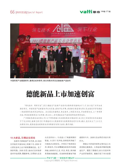
德能公司的技术研发主管在会上向来宾做主题演讲,从系统技术集成到精益生产,描绘了德能在2013年技术和产品的详细规划,着重介绍了本次经销德能新品上市加速创富“领先技术领军行业”,2013德能空气能新产品发布会暨热泵创富峰会于3月28日在广州市永成酒店举行。
中国热泵产业联盟秘书长宋忠奎、副秘书长申隽,香港著名影星曾志伟以及全国近四百位德能一级经销商代表共同出席会议。
会议通过创富峰会、新品发布、工程技术交流、市场营销交流、工厂参观等内容,帮助经销商朋友少走弯路、树立信心,夯实德能在空气能热泵领域的领军地位。
广州德能热源设备有限公司(以下简称德能)总经理张载澎对德能同仁在2012年取得的各项成绩给予了充分肯定,接着又将2013年德能的8大发展规划与经销商朋友进行分享;最后,张总设立了2.5亿元的销售目标,勉励在座经销商朋友共同朝着目标努力奋进、携手共赢。
中国热泵产业联盟领导、番禺区政府领导、曾志伟等共同见证德能新产品发布66特别报道Sp e c i a l R e p o r t太阳能·空气能商大会重点推介的10款新型空气源热泵产品。
“2013年,是热泵行业发展极为关键的一年,也是进入行业洗牌、优胜劣汰极富挑战的一年,我们一定要更加努力通过不断的技术创新,改进、优化产品,做好全方位的技术服务,扩大热泵应用领域,使得热泵行业从热水器品类里全行业年产值不足50亿的局面中突围,达到1万亿级市场规模!”张载澎总经理在2013年度德能空气能新品发布会暨热泵创富会上说。
《河南水利与南水北调》2023年第9期南水北调大型输水渡槽结构缝渗水处理技术郑晓阳,陈嘉敏(中国南水北调集团中线有限公司河南分公司,河南郑州450000)摘要:输水渡槽工程是南水北调中线工程关键建筑物之一,文章所述的大型输水渡槽结构缝渗水处理技术已成功应用于南水北调中线工程输水渡槽结构缝处理。
该技术的应用保障了南水北调工程安全,取得了显著的社会、经济和生态环境效益,具有广阔的推广应用前景。
主要从输水渡槽结构缝渗水处理背景及必要性分析、渗水原因分析、渗水处理技术、主要创新点及特点、修复处理技术对比等方面进行详细阐述,希望能够为其他渡槽结构缝设计、施工、维护提供了借鉴。
关键词:输水渡槽;结构缝;渗水处理;修复;止水中图分类号:TV672.3文献标识码:A文章编号:1673-8853(2023)09-0072-021结构缝渗水处理的背景及必要性分析针对南水北调输水渡槽结构缝渗漏水问题,为确保南水北调工程安全和供水效益,有必要开展输水渡槽结构缝处理技术研究。
2结构缝渗水原因分析2.1渡槽自身的原因渡槽的结构性能直接关系到渡槽的使用性能,如果渡槽自身的结构不合理,结构缝过宽或过窄、止水带选型不合理、止水带位置布置不合理等都可能导致止水带使用寿命缩短或止水带止水效果不佳等问题。
在结构方面,结构缝预留止水槽的宽度、形式,预留钢筋的布置等均对止水效果有一定的影响。
在止水材料方面,橡胶止水常用于渡槽结构缝防水,但结构缝部位橡胶止水容易受到温度的影响;紫铜止水具有延展性好、造价相对较高。
2.2施工原因渡槽结构缝施工过程中作业不规范也是导致后期结构缝渗水的主要原因。
3结构缝渗水处理3.1水下修复技术水下修复技术可以在确保输调水工程正常供水的工况下开展,具有施工工艺简单,经久耐用,不损坏工程主体结构,不影响供水水质等特点。
此技术结构简单,易于操作,处理方式虽以表面封闭为主,但充分考虑结构缝的变形及结构缝处理耐久度要求,处理时采用SR 柔性材料和SR 鼓包形式对结构缝进行封堵,表面采用盖片保护和螺栓紧固。
3M驾驭企业四季的成功之道
李健
【期刊名称】《IT时代周刊》
【年(卷),期】2004(000)12X
【摘要】如同生态系统一样.各种类型的企业都进行着不断地循环,经历着截然不同的4个阶段或4季:创新、成长、改善和衰退。
【总页数】3页(P72-74)
【作者】李健
【作者单位】《IT时代周刊》特约记者
【正文语种】中文
【中图分类】TN915
【相关文献】
1.上网企业如何驾驭营销航船——论企业网络营销走向成功的十大导向 [J], 曾晓洋
2.满足市场需求力助客户成功r沃尔沃建筑设备总裁Martin Weissburg谈企业成功之道 [J], 陈能诵
3.企业发展过程中的成功要素结构变迁——韩国三星企业集团成功之道 [J], 王翔
4.3M驾驭企业四季的成功之道 [J], 李健
5.创新——企业生存之道贴近客户才能做到——专访3M(中国)电子、电力及通讯事业部总经理——丁泓禹 [J], 胡平生
因版权原因,仅展示原文概要,查看原文内容请购买。
上海超越贸易商峰会召开
佚名
【期刊名称】《《中国眼镜科技杂志》》
【年(卷),期】2010(000)012
【摘要】近日.上海超越眼镜有限公司会聚了全国各地的部分贸易商,在丹阳新世纪大酒店会议厅召开了贸易商峰会。
上海超越眼镜有限公司常务董事霍白主持峰会.会上贸易商争相发言.特邀嘉宾丹阳眼镜协会秘书长汤金斌致辞.并介绍了丹阳眼镜的现状。
【总页数】1页(P75-75)
【正文语种】中文
【中图分类】TS959.6
【相关文献】
1.2014中国(上海)智慧城市创新发展峰会召开-“2014上海智慧城市建设十大优秀应用”评选活动专家评审团成立 [J], 本刊编辑部
2.上海:艾瑞上海峰会召开 [J],
3.中国有色金属峰会暨上海有色网年会在上海召开 [J], 曲永祥; 张庆
4.世界巨型开放大学峰会11月在上海召开——峰会项目执行人王一兵教授答本刊记者问 [J], 汪洪宝
5.全国社区卫生服务发展论坛暨上海市社区卫生服务发展特色交流峰会在上海市召开 [J],
因版权原因,仅展示原文概要,查看原文内容请购买。
20世纪晚期英国消费语境下的设计产业
陈红玉
【期刊名称】《服饰导刊》
【年(卷),期】2014(000)004
【摘要】20世纪晚期英国处于成熟的消费社会之下,设计师的职业化、设计领军产业的发展使设计成为社会政治、经济以及文化中的内在动力和显性因素,这与当时社会环境和商业消费实践紧密联系,在对强调服务商业的传统中,设计产业发展的相关要素在以消费为核心的环境下联合为一个围绕商业的成熟体系。
这一时期英国以设计产业立国,形成了以政府为引领和以市场为导向的设计产业体系,并使设计产业成为其创意产业的重要组成部分。
英国以设计产业引领社会创新的独特做法与政策经验等可对当前国家创新转型和"中国创造"有一定的借鉴。
【总页数】5页(P67-71)
【作者】陈红玉
【作者单位】北京市社会科学院
【正文语种】中文
【中图分类】F416.86
【相关文献】
1.消费语境下的“本色表演”——20世纪30年代中国电影女星的文学包装 [J], 许航
2.20世纪晚期英国的时尚与设计运动 [J], 陈红玉;
3.20世纪晚期英国消费语境下的设计产业 [J], 陈红玉
4.20世纪晚期英国的时尚与设计运动 [J], 陈红玉
5.文学传播视角下的英国左翼文学r——评《另一种声音:20世纪英国左翼文学研究》 [J], 黄丽华
因版权原因,仅展示原文概要,查看原文内容请购买。

33002213.00ConceptIEC block library Part: EXPERTS840 USE 504 00 eng Version 2.623Table of ContentsAbout the book . . . . . . . . . . . . . . . . . . . . . . . . . . . . . . . . . . . . . . .5Part I General information on the EXPERTS block library. . . . 7Overview. . . . . . . . . . . . . . . . . . . . . . . . . . . . . . . . . . . . . . . . . . . . . . . . . . . . . . . . 7Chapter 1Parameterizing functions and function blocks . . . . . . . . . . . . .9Parameterizing functions and function blocks. . . . . . . . . . . . . . . . . . . . . . . . . . . . 9Part II EFB descriptions . . . . . . . . . . . . . . . . . . . . . . . . . . . . . . . 13Overview. . . . . . . . . . . . . . . . . . . . . . . . . . . . . . . . . . . . . . . . . . . . . . . . . . . . . . . 13Chapter 2ERT_854_10: Data transfer EFB . . . . . . . . . . . . . . . . . . . . . . . .15Chapter 3ERT_TIME: Time transfer to the ERT854 . . . . . . . . . . . . . . . . .31Chapter 4EXFR: Feedback data enable for Experts. . . . . . . . . . . . . . . . .35Chapter 5EXRB: Accepting feedback values from the expert . . . . . . . .37Chapter 6EXWB: Transferring set points to the expert. . . . . . . . . . . . . .41Chapter 7MUX_DINTARR_125: Multiplexer for arrays of thedata type DIntArr125. . . . . . . . . . . . . . . . . . . . . . . . . . . . . . . . . .43Chapter 8MVB_IN: Data exchange between CPU and MVB-258A . . . . .45Chapter 9MVB_INFO: Requesting bus data via MVB. . . . . . . . . . . . . . . .49Chapter 10MVB_OUT: Data exchange between AS-BMVB-258A andCPU . . . . . . . . . . . . . . . . . . . . . . . . . . . . . . . . . . . . . . . . . . . . . . .53Chapter 11MVB_RED: Switching redundant source ports . . . . . . . . . . . .57Chapter 12SIMTSX: TSX Simulation . . . . . . . . . . . . . . . . . . . . . . . . . . . . . .61Chapter 13ULEXSTAT: Expert Status Signals . . . . . . . . . . . . . . . . . . . . . .63Glossary. . . . . . . . . . . . . . . . . . . . . . . . . . . . . . . . . . . . . . . . . . . . . . .67 Index. . . . . . . . . . . . . . . . . . . . . . . . . . . . . . . . . . . . . . . . . . . . . . .914840 USE 504 00 October 20025About the bookAt a GlanceDocument Scope This documentation will help you in configuring the functions and the function blocks.Validity NoteThis documentation applies to Concept 2.6 in Microsoft Windows 98, Microsoft Windows 2000 and Microsoft Windows NT 4.x.Related DocumentsUser CommentsWe welcome your comments about this document. You can reach us by e-mail at TECHCOMM@Note: Additional up-to-date tips can be found in the Concept README data.Title of Documentation Reference Number Concept Installation instructions 840 USE 502 00Concept Installation Instructions 840 USE 503 00Concept-EFB User Manual 840 USE 505 00Concept LL984 Block Library840 USE 506 00About the book6840 USE 504 00 October 2002840 USE 504 00 October 20027IGeneral information on the EXPERTS block libraryOverviewIntroduction This section contains general information about the EXPERTS block library.What’s in this part?This part contains the following chapters:ChapterChapternamePage1Parameterizing functions and function blocks9General information8840 USE 504 00 October 2002840 USE 504 00 October 200291Parameterizing functions and function blocksParameterizing functions and function blocksParameterization10840 USE 504 00 October 2002GeneralEach FFB consists of an operation, the operands needed for the operation and an instance name or function counter.OperationThe operation determines which function is to be executed with the FFB, e.g. shift register, conversion operations.OperandThe operand specifies what the operation is to be executed with. With FFBs, this consists of formal and actual parameters.FFB(e.g. ON-delay)Item name/Function counter(e.g. FBI_2_22 (18))Operation(e.g. TON)OperandActual parameterVariable, element of amulti-element variable, literal, directaddress(e.g. ENABLE, EXP .1, TIME, ERROR, OUT,%4:0001)Formal parameter(e.g. IN,PT,Q,ET)TONENABLE EXP.1TIMEEN IN PTENO Q ETERROR OUT%4:00001FBI_2_22 (18)Parameterization840 USE 504 00 October 200211Formal/actual parameters The formal parameter holds the place for an operand. During parameterization, an actual parameter is assigned to the formal parameter.The actual parameter can be a variable, a multi-element variable, an element of a multi-element variable, a literal or a direct address.Conditional/ unconditional calls"Unconditional" or "conditional" calls are possible with each FFB. The condition is realized by pre-linking the input EN.l Displayed ENconditional calls (the FFB is only processed if EN = 1)l EN not displayedunconditional calls (FFB is always processed)Calling functions and function blocks in IL and STInformation on calling functions and function blocks in IL (Instruction List) and ST (Structured Text) can be found in the relevant chapters of the user manual.Note: If the EN input is not parameterized, it must be disabled. Any input pin that is not parameterized is automatically assigned a "0" value. Therefore, the FFB should never be processed.Parameterization12840 USE 504 00 October 2002II EFB descriptionsOverviewIntroduction These EFB descriptions are listed in alphabetical order.What’s in this part?This part contains the following chapters:Note: The number of inputs of some EFBs can be increased to a maximum of 32 by changing the size of the FFB symbol vertically. Please refer to the description of the individual EFBs to see which EFBs are involved.Chapter Chaptername Page 2ERT_854_10: Data transfer EFB153ERT_TIME: Time transfer to the ERT854314EXFR: Feedback data enable for Experts355EXRB: Accepting feedback values from the expert376EXWB: Transferring set points to the expert417MUX_DINTARR_125: MUX_DINTARR_125: Multiplexer forarrays of the data type DIntArr12543 8MVB_IN: Data exchange between CPU and MVB-258A459MVB_INFO: Requesting bus data via MVB49 10MVB_OUT: Data exchange between AS-BMVB-258A andCPU53 11MVB_RED: Switching redundant source ports57 12SIMTSX: TSX Simulation61 13ULEXSTAT: Expert Status Signals63840 USE 504 00 October 200213EFB descriptions14840 USE 504 00 October 20022 ERT_854_10: Data transfer EFBOverviewIntroduction This chapter describes the ERT_854_10 block.What’s in this chapter?This chapter contains the following topics:Topic PageBrief description16 Representation16 Mode of Functioning19 EFB configuration20 Data Flow21 Simple example25 Other functions26Use of the DPM_Time Structure for the synchronization of the internal ERTclock26 Using the ERT >EFB time data flow27840 USE 504 00 October 200215ERT_854_10: Data transfer EFB16840 USE 504 00 October 2002Brief descriptionFunction descriptionThe ERT_854_10 EFB provides the programmer with a software interface to the ERT 854 10 module. It allows easy access to functions like counters, time stamp, status or time synchronization. Using the input and output registers, theERT_854_10 EFB can coordinate the flow of Multiplex data from the ERT to the PLC. It also ensures that the intermediate counter values are stored in an internal memory area until the data is complete, so a consistent set of all counter values is made available to the statement list. A flag "New data" is always set for every data type if the input data type was copied into the corresponding EFB output structure. The parameters EN and ENO can also be configured.RepresentationSymbolFunction Block representation:ERT_854_10BoolArr32Input BOOLND_TT ERT_10_TTag TT_Data BOOLND_Count UDIntArr32Cnt_Data BOOL ND_Stat WORDStatus SLOT INT ACK BOOL CL_TT BOOL CL_Count BOOL T_EN BOOL Time_INDPM_TimeERT_854_10: Data transfer EFB840 USE 504 00 October 200217Parameter descriptionDescription of the function block parameters:Parameter Data type MeaningSLOTINTThe Slot index is assigned to the ERT-EFB from either the QUANTUM EFB or DROP EFB and contains the configured input and output references (3x and 4x registers)ACK BOOLEvent confirmation: Setting ACK signals that the user is ready to receive the next result and deletes the TT_Data register. If ACK remains set, "continuous operation" is done.CL_TT BOOL Delete the ERT event FIFO buffer by setting CL_TT. Storage of events is blocked until the CL_TT is reset to 0.CL_Count BOOL Delete all ERT counters by setting CL_Count. Counting is interrupted until CL_Count is reset to 0.T_EN BOOL Enables a time transfer, e.g. from the ESI via Time_IN, if set Time_INDPM_TimeStructure of the input time, e.g. from the ESI, for timesynchronization of the ERT (contains the edge controlled time synchronization in the "Sync" element)Input BOOLArr32Output array for all 32 digital inputs in BOOL format(also provided in the form of word references as 3x registers 1+2)ND_TT BOOLFlag, new data in TT_Data structure: remains set until user confirmation with ACKTT_DataERT_10_TTag Event message output structure with time stamp. An event isheld and NDTT is set to 1 until there is a user enable with ACK = 1.ND_Count BOOL Flag, new counter data in Cnt_Data structure: The value 1 is set for only one cycle and is not acknowledged.Cnt_DataUDIntArr32Output array for 32 counter values (is overwritten after the EFB has received a complete set of consistent counter values (configured as:8, 16, 24, or 32).ND_Stat BOOL Flag; new status data in status word: The value 1 is set for only one cycle and is not acknowledged.StatusWORDOutput word for EFB/ERT status (for internal details see Data Flow, p.21)ERT_854_10: Data transfer EFB18840 USE 504 00 October 2002Internal time synchronizationStructure of DPM_Time for ERT internal time synchronization e.g. via the ESI:Event structureEvent structure of the ERT_10_TTag with 5 Byte time stamp (further information can be found in Data Flow, p.21):Element Element type MeaningSync BOOL Clock synchronization with positive edge (hourly or on command)Ms WORD Time in milliseconds Min BYTE Time invalid / minutes Hour BYTE Summer time / hoursDay BYTE Day of the week / Day in the month Mon BYTE Month YearBYTEYearElement Element type MeaningUser BYTE Complete time / user number [module number]Input BYTE Event set type / No. of the first input In BYTE Event data: 1, 2 or 8 managed positions Ms WORD Time in milliseconds Min BYTE Time invalid / minutes Hour BYTE Summer time / hoursDayBYTEDay of the week / Day of the monthERT_854_10: Data transfer EFB840 USE 504 00 October 200219Mode of FunctioningERT data transferThe number of I/O words available on the local and remote subracks is limited to 64 inputs and 64 outputs. For this reason, the number of ERT modules which can be used per local/remote backplane is limited to 9, with the currently selected minimum requirements of 7 input words and 5 output words per module.The size of the required ERT data transfer is considerably larger:l 32 counters = 64 words,l an event with a 5 byte time stamp = 4 words,l 32 digital values and the ERT status = 3 words.These inconsistent size requirements necessitate the use of a special transfer EFB called ERT_854_10 to execute the required operations on the PLC and to adjust the ERT representation of the data in Multiplex form. An EFB is required for every ERT module.To simplify matters, only the EFB parameters which will actually be used need to be configured. This saves on the amount of configuration effort, particularly when the counter inputs and event inputs are not mixed together. Unfortunately memory cannot be reserved for this because Concept has occupied the outputs with invisible dummy variables.Basic structure of the ERT_854_10 input register block with seven 3x registers for transfer from the ERT to the PLCBasic structure of the register blockERT_854_10 input register block:ContentsFunctionDigital inputs 1 (16)Digitally processed input data which is cyclically updated (the module’s input address corresponds to that of the digital standard input modules, i.e. inputs 1 … 16 correspond to bits 15 … 0)Digital inputs 17 …. 32Transfer status IN transfer status (TS_IN)MUX 1Multiplex data block for block transfer MUX 2 1 event with 5 byte time stamp orMUX 3 2 counter values of possible configured maximum 32 or MUX 41 status wordERT_854_10: Data transfer EFBSimplified structure of the ERT_854_10 output register block with five 4x registersfor the transfer of the SPS to the ERTERT_854_10 output register block:Contents FunctionTransfer status OUT transfer status (TS_OUT)MUX 1Time data block for the ERT for the clock synchronizationMUX 2MUX 3MUX 4Note: User interface is normally for the inputs and outputs of the ERT_854_10EFB, not the 3x and 4x registers.EFB configurationEFB connection The EFB connection to the input and output references (3x and 4x registers) is accomplished through a graphic connection to the ERT slot number, in the sameway as with analog modules. The currently available QUANTUM and DROP EFBsfrom the ANA_IO library are used as follows: QUANTUM for local and DROP forremote backplanes. These EFBs transfer an integer index to every specified slot,which points to an internal data structure with the configured values. The moduleparameters and the ID are stored there, in addition to the addresses and lengths ofthe assigned input and output references (3x and 4x registers).A significant improvement in the runtime can be achieved by deactivating theQUANTUM or the DROP EFB after the first execution. The average runtime of theERT_854_10 EFB in a CPU x13-0x is approximately 0.6 ms, minimum 0.4 ms,maximum 1.6 ms. Every Quantum or DROP-EFB runs on average at approximately1 ms, min. approx. 0.9 ms, max. approx. 1.3 ms.20840 USE 504 00 October 2002ERT_854_10: Data transfer EFB Data FlowDigital Inputs No flag for new data is provided for this input type. The digital inputs in the first two input register words are updated every second cycle directly by the ERT. The EFBmakes the processed values available as Bool if the BoolArr32 output field has beenconfigured accordingly.Counter Inputs Cyclic updating of the counter values takes significantly longer than for other data types. Counter values are saved as a data record in "Cnt_Data" after a completeseries (configured as: 8, 16, 24 or 32) of time consistent counter values in multiplexform has been transferred from the ERT. The flag for new data "ND_Count" is setfor one cycle.Event Inputs As readiness to receive new events must be actively confirmed by the user, the management of the registers becomes somewhat more complex (a handshakemechanism is required). Event data remain in the data structure ERT_10_TTag andthe flag for new data "ND_TT" stays set until the "ACK" input is set by the user andtherefore requests a new event. The EFB responds to this by resetting "ND_TT" forat least one cycle. After the new event has been sent to the ERT_10_TT registerstructure, "ND_TT" is reset by the EFB. To prevent the new event data from beingoverwritten, the user must take care that the "ACK" input is reset after the EFB hasreset the "ND_TT" flag. This state can then be kept stable to allow the user programenough time for event processing. Each subsequent event which is recorded withthe ERT is temporarily stored within the event FIFO buffer.New events are sent directly from the internal buffer of the EFB in intervals of at least2 cycles for as long as the "ACK" input is set (for the special continuous operatingmode); the effect is, however, that the "ND_TT" only stays set for one cycle. In thisspecial mode, it is still the job of the user program to finish event processing before"ND_TT" signals the transfer of other new events to the ERT_10_TT structurebecause handshake protection by "ACK" is not available in this case.840 USE 504 00 October 200221ERT_854_10: Data transfer EFB22840 USE 504 00 October 2002ERT_10_TTag ERT_10_TTag event structure with 5 byte time stampsNote 1:Interpretation for Byte 2Byte BitsFunction1D0...D6 = Module No.. 0...127D7 = CT Rough time: CT = 1 indicates that this time stamp contains the whole time value including month and year in bytes 2 + 3. The Module no. can be set in any way in the parameter screen.2D0…D5 = input no.D6 = P1D7 = P2No. of the first input of the event group: 1 (32)Type of the event message (P2, P1). 1.. 59 see Note 1:, p.22[Month value if CT = 1]3D0…D7 = data from the event group (D7…D0 with right alignment)1, 2 or 8 managed positions [Month value if CT = 1]4Time in milliseconds (least significant byte)0 ...59999 milliseconds (max. 61100) see Note 2:, p.235Time in milliseconds (most significant byte)0 ...59999 milliseconds (max. 61100) see Note 2:, p.23 and Note 3:, p.236D0...D5 = minutes D6 = R D7 = TI Minutes: 0 (59)Time invalid: TI = 1 means invalid time / reserved = 0 see Note 3:, p.237D0...D4 = hours D5 = R D6 = R D7 = DS Hours: 0 (23)Summer time: DS = 1 indicates that summer time is set With switchover from ST -> WT, hour 2A has ST, and hour 2B has WT8D0...D4 = DOW D5...D7 = DOMWeekday: Mon-Sun = 1...7Day of the month: 1 (31)The code corresponds to CET and thus deviates from the standard used in the US, Sun = 1.D7 D6Type of the event message D5...D0No. of the first input of the event group0 1 1 pin message 1 ... 32Input pin number 1 0 2 pin message 1, 3, 5, ...31First input of the group 1 18 pin message1, 9, 17, 25First input of the groupERT_854_10: Data transfer EFB840 USE 504 00 October 200223Note 2:The value for the milliseconds is a maximum of 61100 ms with the second of transition (61000 plus a tolerance of 100 milliseconds)Note 3:For time stamps containing an invalid time (TI = 1), the time in milliseconds is set to FFFF HEX. Minutes, hours and DOW/DOM values are invalid (i.e. undefined).Rough Time OutputIf the "rough time declaration" has been activated during the ERT configuration, the transfer of the complete time (with month/year) is executed under the following conditions: when the month changes, after the module restarts, during every start or stop of the PLC user program, when the event FIFO buffer is deleted, when the clock is started or set. The transfer of this complete time output without the data input values is "triggered" basically takes place through a correct time stamped event. If this does not happen the values remain "stuck" in the ERT until an event occurs. Within the time stamp of a "rough time output", the CT bit is always set so that byte 2 contains the information about the month, byte 3 the information about the year and bytes 4 to 8 show the same time stamp values of the triggering event, which is immediately followed by the event message for rough time output.Status InputsThe flag for new status data "ND_Stat" is set for one cycle. The status inputs can be overwritten after 2 query cycles.The status word contains EFB and ERT error bits Assignments of the Error BitsInternal structure of the EFB/ERT status word:EFB error bitsERT error bitsD15 ...D14D13D12D11D10D9D8D7D6D5D4D3D2D1D0ERT_854_10: Data transfer EFB24840 USE 504 00 October 2002ERT Error Bits D8 ... D0 ERT error bitsWhen configuring the , p. Sreens parameter, some of these errors can be assigned to grouped error messages with the "F" light as well as the module ’s error byte within the status table. All other errors are then defined as warnings.D11 ... D9 reservedEFB Error BitsD15 ... D12 EFB error bits:Bit Abbreviation Meaning D0FW Firmware errors, self test errors within EPROM, RAM or DPM (severe module errors)D1FP Parameter errors (severe internal errors)D2TEExternal time reference error (time-basis signal disrupted or not available)D3TU Time became invalid D4TA Time is not synchronized (Free running mode, permanent running without time error message, see also:Without power reserve, p.27D5PF FIFO buffer overflow (loss of the most recent event data)D6PH FIFO buffer half fullD7DC Dechattering active (some event data lost)D8CEERT communication error (procedure errors or time out)Bin.Hex.Meaning1000 8 HEX EFB communication time out 0101 5 HEX Wrong slot0110 6 HEXHealth status bit is not set (ERT appears not to be available)other valuesinternal errorERT_854_10: Data transfer EFB840 USE 504 00 October 200225Online error displayThe following ERT/ERB error messages are displayed in the Online → Event viewer Concept window with an error number and explanation.EFB error messages:ERT error messages:Simple exampleStructure diagramPrinciple structureMessage Error Meaning-2710User error 11EFB communication time out -2711[User error 12] =EFB internal error -2712[User error 13] =EFB internal error -2713[User error 14] =EFB internal error -2714[User error 15] =EFB internal error -2715[User error 16] =Wrong slot-2716[User error 17]Health status bit is not set (ERT appears not to be available)-2717[User error 18]EFB internal errorMessage Error Meaning -2700User error 1]ERT internal error .........-2707[User error 8]ERT internal error-2704[User error 5]ERT communication timeout (e.g. EFB disabled too long)QUANTUMSLOT1SLOT2SLOT3IN3ERT_854_10Input ND_TT TT_Data ND_Count Cnt_Data ND_Stat StatusSLOT ACK CL_TT CL_Count T_EN Time_INFBI-XXX 11DPM_TimeSTRUCTURE with cyclically actualized Time (of ESI module)User data structureBoolArr32ARRAY for 32Digital inputsERT_10_T-Tag STRUCTURE saves an event with time stamp UDIntArr32ARRAY for 32Counter inputsStatus wordERT_854_10: Data transfer EFB26840 USE 504 00 October 2002Other functionsInput markersSetting the input marker "CL_TT" causes the FIFO buffer event of the ERT to be cleared. Setting the markers for one cycle is sufficient.Setting the input marker "CL_Count" causes the ERT counter to be cleared by the ERT. Setting the markers for one cycle is sufficient.Use of the DPM_Time Structure for the synchronization of the internal ERT clockTimesynchronizationIf the time can not be synchronized through a standard time receiver, the time information can alternatively be transferred from the 140 ESI 062 01 communication module. The ESI makes the updated time available in a DPM_Time structure directly using the "Time_IN" parameter. The data structure can also be filled by the user program and the corresponding bits can be set. In this manner, the time can also be set, for example, by the CPU.With power reserveAs soon as the "clock" parameter of the ERT is configured to "internal clock" with a power reserve not equal to zero (i.e. not free running), the EFB must use the time provided by the ESI for synchronizing the internal ERT clock. Until the firstsynchronization has taken place, the ERT sends back "status" output word with the bit "invalid time" set (Bit 3 TU).The conditions of the first synchronization of the internal ERT using above the DPM_Time structure are:The EFB Parameter "T_EN" must change from 0 to 1 to enable the time setting.The time in "TIME_IN" provided by ESI must be represented as follows:l valid (i.e. the bit for the message "time invalid" in "Min" value must not be set),l and the values in "Ms" must change continually.If, at a later point in time, the time data is invalid or no longer set, the TU changes to 1 after the configured power reserve has run out.The synchronization/setting of the internal ERT clock takes place using the DPM_Time structure, if:l EFB-Parameter "T_EN" is set to 1 to enable the time setting.l The time data in "Time_IN" provided by ESI are valid (i.e. the "Time invalid" Bit in the "Min"value must not be set).l The status of the DPM_Time element "Sync" changes from 0 to 1. This change is done every complete hour by the 140 ESI 062 01, but can also be triggered by a suitable telecontrol command.ERT_854_10: Data transfer EFB840 USE 504 00 October 200227The precision of the ESI and ERT synchronized time can be influenced by delay caused by the PLC cycle time, as well as by the cumulative components, which reflect the differences of the ERT software clock (< 360 milliseconds/second).Without power reserveIf the "clock" parameter of the ERT was configured as an "internal clock" in free running mode (with a power reserve of zero), the internal clock starts with a default setting at hour 0 on 1/1/1990. In this case, the time can also be provided by using the DPM_Time data structure of the 140 ESI 062 01 module, as described above. As there is no power reserve to "run out", the time will never be invalid and the bit "Time not synchronized" is always set in the "status" output word (Bit 4 TA) which is returned by the EFB, .Using the ERT >EFB time data flowApplication Examples:This section shows an internal function which is made available by the ERT for diagnostics and development. It covers the cyclic transfer of the ERT internal time to the corresponding EFB in greater intervals. This time can be used for display or setting the PLC clock and so on, irrespective of whether it comes from the free-running internal clock or was synchronized through an external reference clock signal. The time appears as a DPM_Time structure beginning at word 4 of the IN register block of the ERT. The following diagram shows the program elements involved in selection.Startupinformation:During the I/O addressing, the IN references 30001 …30007 were assigned to an ERT_854_10. The IN transfer status (TS_IN) in the third word of the register block is sent to an OR_WORD block. A DPM_Time structure is defined in the variable editor as Variable Mux_IN in the fourth word of the IN register block and hasaddress 30004 ... 30007. This variable is given as an input to the MOVE block. The MOVE block output is a DPM_Time structure defined by the variable editor as variable ERT_Time.Typical recording mechanism for ERT time dataNote: The ERT_854_10-EFB must be active and error free.OR_WORD%3:000316#FF1FEQ_WORD16#FFBFR_TRIG ND_Time QCLKMOVEERT_Time ENMux_IN ENO(DPM_Time Struktur)(DPM_Time Struktur)(BOOL)ERT_854_10: Data transfer EFB28840 USE 504 00 October 2002Explanation:The MOVE block transfers the time data (which is cyclically stored in the MUX range of the IN register block) to the DPM_Time structure ERT_Time of the user as soon as the OR_WORD and the EQ_WORD block signal for a time data transfer. R_TRIG provides a signal in "ND_Time" for one cycle to allow further processing of the time data. The BOOL "Sync" element value of the ERT_Time should begin to "tick" during each new transfer from the ERT. There is a new transfer after a maximum of each 200 PLC cycles.Example 1: Using time values for display (or with SET_TOD-EFB)A number of simple logical operations is needed to obtain a meaningful display of the time information of the DPM_Time structure. The same commands can also be used for the ERT_10_T Tag structure. As example 2 deals with setting the PLC clock while using the SET_TOD-EFB, individual values are directly converted into the required formats.SET_TOD requires that the WORD millisecond value "ms" is converted into a BYTE second value. The BYTE minute value "Min" contains the error bit which must be removed (values greater than 127 are invalid).Conversion of the WORD millisecond value into a seconds BYTEThe BYTE value "Day" contains week and calendar day values. The weekday Monday is displayed as 1 in the DPM_Time structure. The weekday parameter in SET_TOD uses the value 1 for Sunday.Note: The reference data editor (RDE) can provide the "ms" value directly in the Uns-Dec-WORD format and the "Min" value in the Dec-BYTE format.WORD_TO_UINTERT_Time.MsAND_BYTEERT_Time.Min16#3FErt_MinaDIV_UINT1000UINT_TO_BYTEErt_Seca。
品质生活新产品
佚名
【期刊名称】《中国品牌》
【年(卷),期】2012(000)004
【摘要】路易威登TambourCapsuleVoyage系列这款自动计时码表的表盘设计灵感同样来源于旧时赛车的仪表盘,强烈的动感营造出冷工业时代的复古气息。
表盘暖灰色的基调中跳跃着几抹鲜艳的红色,在强调整体设计同时,也使刻度数值更加清晰醒目。
【总页数】2页(P120-121)
【正文语种】中文
【中图分类】F713.36
【相关文献】
1.基于高品质生活理念的餐饮浪费治理研究 [J], 陈竹君
2.天境:产品精研磨,塑品质生活 [J],
3.高品质生活的居民感知与创造路径--基于重庆市39个区县的调查分析 [J], 孟东方
4.论创造高品质生活的理论基础 [J], 程新平;刘富胜
5.农垦直供会员店品质生活新概念 [J], 任安静
因版权原因,仅展示原文概要,查看原文内容请购买。
解密完美品牌基因
黄永建
【期刊名称】《知识经济.中国直销》
【年(卷),期】2007(000)008
【摘要】“从2007年开始的第一个十年,完美公司希望通过以技术、质量、服务为载体,全力将完美打造成全球性品牌。
”
【总页数】6页(P22-27)
【作者】黄永建
【作者单位】《知识经济.中国直销》记者
【正文语种】中文
【中图分类】F270
【相关文献】
1.海德堡青浦工厂发现之旅:解密完美品质的炼成法则 [J], 薛金萍
2.“橡皮几何学”与物理学完美结合解密——2016年诺贝尔物理学奖 [J], 何龙;潘天俊;孟卫东
3.解密完美,无限极胜经 [J], 陕丹;胡榕
4.解密区域完美恢复的区域递增式视觉密码方案构造 [J], 胡浩;郁滨;沈刚;张学思
5.解密完美,无限极胜经 [J], 陕丹;胡榕
因版权原因,仅展示原文概要,查看原文内容请购买。
高性能汽车书写历史新未来
阮美勤
【期刊名称】《中国科技产业》
【年(卷),期】1998(000)011
【摘要】@@ 30年后,全世界汽车的数量将从现在的4亿辆猛增到10亿辆,但未来的这些车,其发展趋势是高速、多用途、污染小及安全的高性能汽车.
【总页数】1页(P41)
【作者】阮美勤
【作者单位】无
【正文语种】中文
【中图分类】U461
【相关文献】
1.铸造新的辉煌——兵总汽车摩托车工业的历史和未来 [J],
2.“民族·历史·美学”:当代亚洲新影像的文化书写——评周安华新作《当代电影新势力——亚洲新电影大师研究》 [J], 陈亦水
3.天梭表力洛克系列腕表致敬历史书写未来 [J],
4.天梭表力洛克系列腕表致敬历史书写未来 [J],
5.历史书写的新维度——评黎正光长篇历史小说《仓颉密码》 [J], 袁园
因版权原因,仅展示原文概要,查看原文内容请购买。
美国齿轮制造商协会
郭德华
【期刊名称】《标准科学》
【年(卷),期】2004(000)001
【摘要】@@ 英文名称:AMERICAN GEAR MANUFAC-TURERS ASSOCI A TIONrn缩写名称:AGMA
【总页数】2页(P54-55)
【作者】郭德华
【作者单位】中国标准化研究院标准馆
【正文语种】中文
【中图分类】F171.2
【相关文献】
1.海外家电业四大热点——第三届世界家电协会峰会和美国家用电器制造商协会年会侧记 [J], 王海涛
2.美国轮胎制造商协会修正2019年美国轮胎出货量预估 [J], 宇虹
3.美国齿轮制造商协会(AGMA)颁布新的齿轮标准 [J], William A.Bradley;施颖
4.美国橡胶制造商协会称2009年上半年美国轮胎出货量下降 [J], 冯涛
5.齿轮测量中心的制造商——美国M&M精密系统公司 [J], 宣洪冰
因版权原因,仅展示原文概要,查看原文内容请购买。
2007年全球重大火灾回顾
林火妹
【期刊名称】《亚洲消防》
【年(卷),期】2008(000)001
【总页数】4页(P36-39)
【作者】林火妹
【作者单位】《亚洲消防》记者
【正文语种】中文
【中图分类】TU998.12
【相关文献】
1.2007年全球和中国十大自然灾害事件回顾与启示 [J], 孙刚;曲国胜;宁宝坤;张鹤
2.2007年全球商业通信卫星行业简要回顾 [J], 许彤
3.高位稳定运行渐成钼市主旋律——2007年全球钼市场回顾及后市展望 [J], 徐爱华
4.全球经济依旧是影响基本金属市场的关键——2007年12月份基本金属市场回顾及展望 [J], 陈进华;忻佳毅
5.2007年全球硫的生产和消费回顾 [J], 张宝财
因版权原因,仅展示原文概要,查看原文内容请购买。
全球化的汽车工业
陈小复
【期刊名称】《上海汽车》
【年(卷),期】1996(000)006
【摘要】世界汽车工业跨国公司早就越出了国界,本文叙述了各大集团在全球范围广泛剧烈兑的局面。
东南亚,东欧,印度等,成了世界汽车大国利用廉价劳动力的零部件基地,同时也待开拓的潜在市场。
【总页数】6页(P50-55)
【作者】陈小复
【作者单位】上海汽车工业技术中心
【正文语种】中文
【中图分类】F416.471
【相关文献】
1.中国汽车工业在经济全球化形势下的发展方向 [J], 郭璐璐;;
2.面对高科技、新经济与全球化发展我国汽车工业的三重联动对策 [J], 欧光军;胡树华
3.英国汽国工业之旅(二)全球化经济背景下的英国汽车工业 [J], 朱海霞
4.汽车工业全球化发展趋势——汽车零部件企业的发展战略动向 [J], 杨妙梁
5.从全球化看美国汽车工业的发展态势 [J], 吴启金
因版权原因,仅展示原文概要,查看原文内容请购买。