
MGPM20-125Z资料下载
- 格式:doc
- 大小:1.09 MB
- 文档页数:5


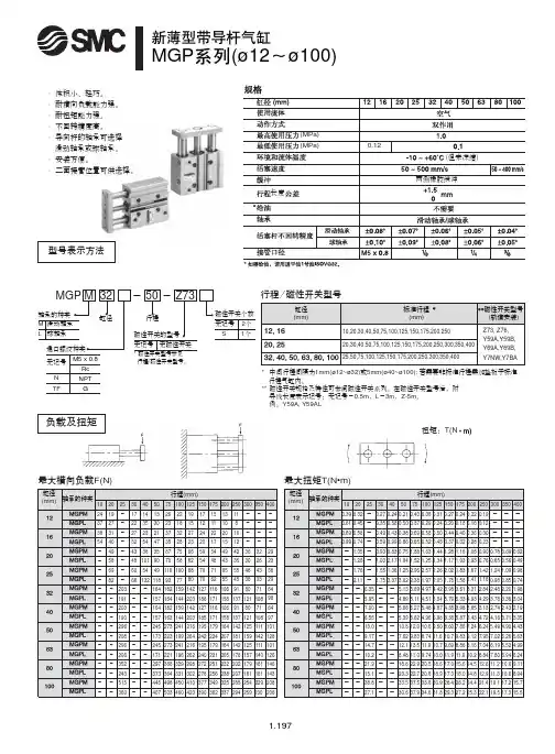
!"#$%MGP (ø12ø100)· 体积小、轻巧。
· 耐横向负载能力强。
· 耐扭矩能力强。
· 不回转精度高。
· 导向杆的轴承可选择滑动轴承或球轴承。
· 安装方便。
· 二面接管位置可供选择。
最大横向负载F(N) 最大扭矩T(N •m)扭矩:T(N型号表示方法* 中间行程间隔为1mm(ø12~ø32)或5mm(ø40~ø100); 若需要非标准行程需加垫板于标准 行程气缸内。
** 磁性开关规格及特性可参阅磁性开关系列。
在磁性开关型号后,附 导线长度表示记号:无记号-0.5m ,L -3m ,Z-5m 。
例:Y59A, Y59AL行程/磁性开关型号MGPM , MGPL 共同尺寸表4-NN通孔4-øOA 通孔4-øOB 沉孔深OLPA + 行程XX部详细图C + 行程B + 行程A + 行程12 ~ ø25深深部深深部部深!"=E FXX 部详细图32 ~ ø63MGPM (滑动轴承)尺寸A,DB,EMGPL (球轴承)尺寸A,DB,E4-NN 通孔4-øOA 通孔4-øOB 沉孔深OLC + 行程B + 行程A + 行程PA + 行程深部深部深深部深ø80 ~ ø100MGPM (滑动轴承)MGPL (球轴承)st = 行程MGPM , MGPL 共同尺寸表XX 部详细图4-NN 通孔4-øOA 通孔4-øOB 沉孔深OLPA + 行程C + 行程B + 行程A + 行程深部深部深部深ø6H7深106H710ø6H7深10ø6H7深1057ø6H 7规格缸径(mm)最高使用压力(MPa)最低使用压力(MPa)缓冲*其它规格参见P.1.197。

![Best Pneumatics MGP M 32 周期杆长度[mm] 参考标准杆长在页47说明书](https://imgs-1438308264.cos.ap-hongkong.myqcloud.com/7c16adc685868762caaedd3383c4bb4cf7ecb7ef.webp)
How to OrderRefer to Standard Strokes on page 47.Compact Guide Cylinder/With End Lock Series MGPø20, ø25, ø32, ø40, ø50, ø63, ø80, ø100For details, refer to p age 47.refer to the table below.*: Solid state auto switches marked with “p ” are produced upon receipt of order.*: Bore sizes 32 to 100 are available for D-P4DW m .*: Bore sizes 25 to 100 are available for D-P3DWA m .*: Lead wire length symbols: 0.5 m·········· N il(Example) M9NW 1 m·········· M (Example) M9NWM 3 m·········· L (Example) M9NWL 5 m·········· Z(Example) M9NWZ*: Since there are other applicable auto switches than listed above, refer to page 66 for details.*: F or details about auto switches with pre-wired connector, refer to the WEB catalog or the Best Pneumatics No. 3. For D-P3DWA m , refer to the WEB catalog .*: Auto switches are shipped together, (but not assembled).*1: W ater resistant type auto switches can be mounted on the above models, but in such case SMC cannot guarantee water resistance.Please consult with SMC regarding water resistant types with the above model numbers.*2: 1 m type lead wire is only applicable to the D-A93.46C o u r t e s y o f C M A /F l o d y n e /H y d r a d y n e ▪ M o t i o n C o n t r o l ▪ H y d r a u l i c ▪ P n e u m a t i c ▪ E l e c t r i c a l ▪ M e c h a n i c a l ▪ (800) 426-5480 ▪ w w w .c m a f h .c o mSymbolRubber bumperSpecificationsStandard StrokesManufacture of Intermediate StrokeLock SpecificationsMade to Order(For details, refer to pages 72 and 89.)*1: 0.1 MPa except the lock unit.*2: M aximum speed with no load. Depending on the operating conditions, the piston speed may not besatisfied. Make a model selection, considering a load according to the graph on pages 16 to 22.Adjust switch positions for operation at both the stroke end and backlash (2 mm) movement positions.Lock position Head end, Rod end Holding force (Max.) N ø20ø25ø32ø40ø50ø63ø80ø1002153305508601340214034505390Backlash 2 mm or less Manual releaseNon-lock type, Lock type*: The minimum stroke for mounting auto switches is 10 stroke or more for two switches, and 5 stroke or more for one switch.*: Intermediate stroke (in 1 mm increments) based on an exclusive body will be available upon request for special.DescriptionSpacer installation type.Dealing with the stroke in 5 mm increments is available by installing spacer with standard stroke cylinder. When a spacer is mounted on the cylinder with an end lock on the rod side, use a special piston rod.Part no.Refer to “How to Order” for the standard model numbers on page 46.Applicable stroke [mm] 5 to 395ExamplePart no.: MGPM50-35-HNA spacer 15 mm in width is installed in a MGPM50-50-HN. C dimension is 119 mm.Theoretical Output*1: The shape is the same as the current product.47Series MGPC o u r t e s y o f C M A /F l o d y n e /H y d r a d y n e ▪ M o t i o n C o n t r o l ▪ H y d r a u l i c ▪ P n e u m a t i c ▪ E l e c t r i c a l ▪ M e c h a n i c a l ▪ (800) 426-5480 ▪ w w w .c m a f h .c o mθModel selection is the same as MGP/standard type.Refer to pages 16 to 23.Model selection Allowable Rotational Torque of Plate.Non-rotating Accuracyof PlateCalculation: (Example) MGPM50-100-HN• B asic Weight + Lock unit additional weight• 5.74 + 0.24 = 5.98 k gFor non-rotating accuracy q without load, usea value no more than the values in the table asa guide.48 CourtesyofCMA/Flodyne/Hydradyne▪MotionControl▪Hydraulic▪Pneumatic▪Electrical▪Mechanical▪(8ø50 or moreø20, ø25: 25 stroke(Rod end lock)ø20 to ø63øø80, ø100ø63 or moreNon-locking type(Head end lock)bore size.*: S ince the seal kit does not include a grease pack, order it separately.Grease pack part no.: GR-S-010 (10 g) Construction/Series MGPM49Series MGPCourtesyofCMA/Flodyne/Hydradyne▪MotionControl▪Hydraulic▪Pneumatic▪Electrical▪Mechanical▪(8)426-548▪www.cmafh.comø63 or moreLock type50C o u r t e s y o f C M A /F l o d y n e /H y d r a d y n e ▪ M o t i o n C o n t r o l ▪ H y d r a u l i c ▪ P n e u m a t i c ▪ E l e c t r i c a l ▪ M e c h aDetailed figure ofsection XXEnd lock mechanism(Manual release lock type)ø25With rod end lockWith head end lockDimensions: ø20, ø25MGPL (Ball bushing),End Lock Mechanism*: For intermediate strokes other than standard strokes, refer to the Manufacture of Intermediate Stroke on page 47.*: Rc, NPT and G ports can be selected. (Refer to page 46.)T-slot dimensions51Series MGPCourtesyofCMA/Flodyne/Hydradyne▪MotionControl▪Hydraulic▪Pneumatic▪Electrical▪Mechanical▪(8)426-548▪www.cmafh.comDetailed figure of section XXEnd lock mechanism(Manual release lock type) With rod end lockWith head end lock*: For intermediate strokes other than standard strokes, refer to the Manufacture of Intermediate Stroke on page 47.*: Rc, NPT and G ports can be selected. (Refer to page 46.)52 CourtesyofCMA/Flodyne/Hydradyne▪MotionControl▪Hydraulic▪Pneumatic▪Electrical▪Mechanical▪(8)426-548▪www.cmDetailed figure of section XXEnd lock mechanism(Manual release lock type) With rod end lockWith head end lock*: For intermediate strokes other than standard strokes, refer to the Manufacture of Intermediate Stroke on page 47.*: Rc, NPT and G ports can be selected. (Refer to page 46.)Dimensions: ø80, ø100MGPL (Ball bushing),End Lock Mechanism53Series MGPCourtesyofCMA/Flodyne/Hydradyne▪MotionControl▪Hydraulic▪Pneumatic▪Electrical▪Mechanical▪(8)426-548▪www.cmafh.comLockReleaseReleasedLockedWith head end lockSeries MGP With End LockSpecific Product PrecautionsBe sure to read this before handling. Refer to the back cover for Safety Instructions.For Actuator and Auto Switch Precautions, refer to Handling Precautions for SMCProducts and the Operation Manual on the SMC website, Use Recommended Air Pressure Circuit.Caution• It is necessary for proper locking and unlocking.Operating PressureCaution1. Supply air pressure of 0.15 MPa or higher to the port on the sidethat has the lock mechanism, as it is necessary for disengagingthe lock.Exhaust Air SpeedCaution1. The lock will engage automatically if the air pressure at the port onthe side that has the lock mechanism becomes 0.05 MPa or less.Be aware that if the piping on the side that has the lock mechanismis narrow and long, or if the speed controller is located far from thecylinder port, the exhaust air speed could become slower, involvinga longer time for the lock to engage. A similar result will ensure ifthe silencer that is installed on the exhaust port of the solenoidvalve becomes clogged.Lock DisengagementWarning1. To disengage the lock, make sure to supply air pressure to theport on the side without a lock mechanism, thus preventing theload from being applied to the lock mechanism. (Refer to therecommended air pressure circuit.) If the lock is disengaged whenthe port on the side that does not contain a lock mechanism is inthe exhausted state and the load is being applied to the lockmechanism, undue force will be applied to the lock mechanism,and it may damage the lock mechanism. Also, it could beextremely dangerous, because the piston rod could movesuddenly.HandlingCaution1. Do not use a 3 position solenoid valve.Avoid using this cylinder in combination with a 3 position solenoidvalve (particularly the closed center metal seal type). If air pressurebecomes sealed inside the port on the side that contains the lockmechanism, the lock will not engage. Even if the lock is engagedat first, the air that leaks from the solenoid valve could enter thecylinder and cause the lock to disengage as time elapses.2. Back pressure is necessary for unlocking.Before starting, make sure that air is supplied to the side that is notequipped with a lock mechanism as shown in the diagram above.Otherwise, the lock may not disengage.(Refer to “Rock Disengagement”.)3. Disengage the lock before installing oradjusting the cylinder.The lock could become damaged if the cylinder is installed with itslock engaged.4. Operate the cylinder at a load ratio of 50% or less.The lock might not disengage or might become damaged if a loadratio of 50% is exceeded.5. Do not synchronize multiple cylinders.Do not operate two or more end lock cylinders synchronized tomove a single workpiece because one of the cylinder locks maynot be able to disengage when required.6. Operate the speed controller under meter-out control.If operated under meter-in control, the lock might not disengage.7. On the side that has a lock, make sure tooperate at the stroke end of the cylinder.The lock might not engage or disengage if the piston of thecylinder has not reached the stroke end.8. Do not use the air cylinder as an air-hydrocylinder. This may result in oil leak.9. The position adjustment of the auto switchshould be performed at two positions; a po-sition determined by the stroke and a posi-tion after the backlash movement (by 2 mm).When a 2-color indication auto switch is adjusted to show green atthe stroke end, the indication may turn red when the cylinderreturns by the backlash. This, however, is not an error.1. Non-locking style manual releaseInsert the bolt, which is provided as anaccessory part, through the rubber cap (it isnot necessary to remove the rubber cap).Screw the bolt into the lock piston and pullthe bolt to disengage the lock. Releasingthe bolt will re-engage the lock.otherwise it may cause malfunction of the locking feature.Manual DisengagementCaution2. Locking style manual releaseTurn 90°counterclockwise while pushing the M/O knob. Lock isreleased when on the cap and OFF mark on the M/O knobcorrespond. (Lock remains released.)When locking isdesired, turn 90°clockwise while fullypushing the M/O knoband correspond onthe cap and ONmark on the M/O knob.Confirm the correctposition by click sound“click”. Otherwise, lockmay not be engaged.54 CourtesyofCMA/Flodyne/Hydradyne▪MotionControl▪Hydraulic▪Pneumatic▪Electrical▪Mechanical▪(8)426-548▪www.cmafh.com。