MoldDesignSpec模具设计规范
- 格式:doc
- 大小:128.00 KB
- 文档页数:7
模具设计规范及要点模具设计是制造业中非常重要的环节,它直接影响到产品的质量和生产效率。
为了确保模具设计的准确性和合理性,制定一系列的规范是非常必要的。
本文将介绍模具设计的规范及其要点。
一、模具设计规范的目的模具设计规范的目的是确保模具具备高质量和高效率的生产能力,并最大限度地减少模具使用过程中的故障和损耗。
通过遵守规范,可以提高模具的使用寿命,减少维修和更换成本,提高生产效率,降低生产成本,提升产品的质量。
二、模具设计规范的要点1.模具设计应符合产品的要求:模具设计必须根据产品的尺寸、形状、材料和数量要求来进行,确保模具可以完美地制造出符合产品要求的零件。
2.模具设计应考虑材料的选择和加工工艺:模具所选材料应具有足够的强度和硬度,以承受生产过程中的高负荷和磨损。
同时,模具的加工工艺应考虑到成本、时间和质量的平衡,确保成型过程的高效和精确。
3.模具设计应遵循安全和可靠性的原则:模具的设计应确保操作过程中的安全性,尽量减少操作人员的伤害和事故发生。
同时,模具的设计要保证其可靠性,能够稳定地工作,并且容易进行维护和修复。
4.模具设计应考虑到工装和夹具的需要:在模具设计过程中,应充分考虑到工装和夹具的配套需求,确保模具能够与其完美配合,提高生产效率和产品质量。
5.模具设计应简化结构:模具的设计应尽量简洁,避免复杂的结构,以减少制造成本和使用成本。
同时,简化结构也有利于操作和维护。
6.模具设计应具备可拆卸性:模具的设计应尽量满足零部件的可拆卸性,使得维护和更换变得容易。
这样可以减少停机时间,提高生产效率。
7.模具设计应合理确定尺寸公差:模具的设计应根据产品的尺寸要求合理确定公差,以确保模具制造出来的零件尺寸准确且符合要求。
8.模具设计应注意冷却系统的布置:模具的冷却系统设计应合理布置,以确保零件的快速冷却和缩短生产周期。
冷却系统的设计也要考虑到冷却介质的供应和排放。
9.模具设计应充分考虑排气和出渣:模具的设计应考虑到充分的排气和出渣,以防止铸件中产生气孔和杂质。

模具设计规范不正确的浇口位置浇口位置对流动熔料前沿的形状和保压压力的效果都起着决定性作用,因此也决定了模制零件的强度和其它性能。
鉴于浇口的位置通常是同注塑零件设计人员和模具设计人员指定的,因此本文特别为这些人员而撰写。
不过,注塑加工厂商也应从计划阶段开始参与,以避免出现那些可以预见的问题。
浇口位置不当可能导致的不利影响半晶质工程聚合物制成的零件即使设计正确,但如果浇口位置不正确,其性能也可能遭到破坏。
无论是增强型树脂还是非增强型树脂,以下症状都明显说明了其性能受到影响:流动熔料前沿形状导致的熔合线和空气气穴都可能影响零件的外观,特别是增强纤维材料,其机械性能将会受到影向。
更改加工条件对这些影响也是无济于事。
如果浇口设在模制件的较薄部分,厚壁的部分会形成收缩痕迹和空隙。
尽管厚壁部分需要更长的保压时间,但由于材料在薄壁部分结晶较快(图1),厚壁部分将不再有熔料供应。
结果是,除了会产生光学和机械问题之外,还会在厚壁区域增大收缩量,在非增强型塑料中甚至会导致翘曲变形。
如果浇口过少并且位置不当,熔料的流动距离可能过长以及注射填充压力过高。
若模具锁定力不足,或者所使用的聚合物粘度低并且结晶速度过慢,这种情况可能导致飞边的增加。
另外,加工工艺“窗口”受到很大限制,因此不再能够通过模制条件微调误差。
最佳浇口位置建议★必须将浇口设计在壁厚最大的区域。
★浇口不能设在高应力区域附近。
★对于长零件,特别是增强型配混料,如电动机可能,应该沿纵向而不是沿横向或在中心设置浇口。
★如果在两个或以上的型腔,零件和浇口应与沿注道对称布置。
★轴向对称零件,例如齿轮、盘、叶片等,最好使用隔板浇口并且应在中心设置浇口,或者在三板模具上设多个浇口,以获得良好的实际流动特性。
★有一体式铰接的零件在布置浇口时,应使熔合线远离铰接点。
在任何情况下。
都应避免将熔料停止流动部分设计在铰接点附近。
★杯形零件(例如小壳体、电容器杯等)的浇口应设计在底座附近,以避免产生空气气穴。
模具设计规范标准规范标准模具设计标准规范1﹑⽬的:确保模具设计规范化,统⼀化.能将设计意图正确的传达给制造部门.避免或减少失误。
2﹑范围:⼯程部设计组接收⼯程部产品组转交的图⽂件、样品等资料到图纸发⾏为⽌之阶段均属之。
3﹑权责:3.1 ⼯程部设计组:负责模具开发设计及设计变更、2D/3D产品图⾯设计、3D建模、设计模具的组⽴图、3D拆模与拆电极、绘制零件图.3.2 现场加⼯各组:加⼯各组的组长,在加⼯前需先审视加⼯图,若发现与原先检讨的不符合或有误,甚⾄不合理,需⽴即反应⼯程部检讨查核后,⽅可继续加⼯。
4. 名词释义:⽆5﹑作图环境标准:5.1⽂字标准5.1.1字体。
数字及英⽂使⽤“Arial”字体,中⽂使⽤“标楷体”。
5.1.2⽂字⼤⼩。
为了使整套图⾯⽂字视觉效果⼀致,在标准图框(即1:1图框,A4为297*210)中,设定字⾼为3.0,宽0.85。
5.2 图⾯标准5.2.1 图框:为了便于查阅,装订,保存,图框统⼀标准如下:A0图框:841*1189横印(附件⼀)A1图框:594*841横印(附件⼆)A2图框:420*594横印(附件三)A3图框:420*297横印(附件四)A4图框:297*210直印(附件五)5.2.2 图⾯要求5.2.2.1零件图⾯按照其在模具当中的位置分类摆放,以便于查找。
5.2.2.2尺⼨标注⽅式。
除了圆以外,所有模板、模仁之尺⼨均采⽤坐标标注⽅式。
5.2.2.3 视图投影关系:第三视⾓法。
5.2.3图档版本版本编号采⽤⼤写字母“A”加上⼀位数字序号,数字序号按照图⽂件完成的时间先后顺序进⾏排列。
例如A1、A2、A3等。
5.2.4 图层与线型:为了便于图形与尺⼨的识别,图层与线型统⼀标准如下:5.3编码原则5.3.1模具结构和主要零件名称如下:5.3.2零件名称与对应的编号如下:5.3.2.1模胚部分编号零件名称编号零件名称A01 上固定板A09 脱料板A02 下固定板A10 推板A03 母模板A11 上流道板A04 公模板A12 电热板A05 母模承板A13 脚垫A06 公模承板A14 浇道脚垫A07 上顶针板A08 下顶针板5.3.2.2镶件部分5.3.2.3⼀般零件部分5.3.2.3⼀般零件部分(续)5.3.2.4特殊零件部分5.3.3编码⽅式5.3.3.1模具编码⽅式。
模具设计标准规范1﹑目的:确保模具设计规范化,统一化.能将设计意图正确的传达给制造部门.避免或减少失误。
2﹑范围:工程部设计组接收工程部产品组转交的图文件、样品等资料到图纸发行为止之阶段均属之。
3﹑权责:3.1 工程部设计组:负责模具开发设计及设计变更、2D/3D产品图面设计、3D建模、设计模具的组立图、3D拆模与拆电极、绘制零件图.3.2 现场加工各组:加工各组的组长,在加工前需先审视加工图,若发现与原先检讨的不符合或有误,甚至不合理,需立即反应工程部检讨查核后,方可继续加工。
4. 名词释义:无5﹑作图环境标准:5.1文字标准5.1.1字体。
数字及英文使用“Arial”字体,中文使用“标楷体”。
5.1.2文字大小。
为了使整套图面文字视觉效果一致,在标准图框(即1:1图框,A4为297*210)中,设定字高为3.0,宽0.85。
5.2 图面标准5.2.1 图框:为了便于查阅,装订,保存,图框统一标准如下:A0图框:841*1189横印(附件一)A1图框:594*841横印(附件二)A2图框:420*594横印(附件三)A3图框:420*297横印(附件四)A4图框:297*210直印(附件五)5.2.2 图面要求5.2.2.1零件图面按照其在模具当中的位置分类摆放,以便于查找。
5.2.2.2尺寸标注方式。
除了圆以外,所有模板、模仁之尺寸均采用坐标标注方式。
5.2.2.3 视图投影关系:第三视角法。
5.2.3图档版本版本编号采用大写字母“A”加上一位数字序号,数字序号按照图文件完成的时间先后顺序进行排列。
例如A1、A2、A3等。
5.2.4 图层与线型:为了便于图形与尺寸的识别,图层与线型统一标准如下:5.3编码原则5.3.1模具结构和主要零件名称如下:5.3.2零件名称与对应的编号如下:5.3.2.1模胚部分编号零件名称编号零件名称A01 上固定板A09 脱料板A02 下固定板A10 推板A03 母模板A11 上流道板A04 公模板A12 电热板A05 母模承板A13 脚垫A06 公模承板A14 浇道脚垫A07 上顶针板A08 下顶针板5.3.2.2镶件部分5.3.2.3一般零件部分5.3.2.3一般零件部分(续)5.3.2.4特殊零件部分5.3.3编码方式5.3.3.1模具编码方式。
模具设计规范随着制造工业的不断发展,模具在各个领域中的应用越来越广泛,模具设计的重要性也日益突显。
模具是产业中的重要生产工具,需遵守一定的设计规范。
本文将从模具设计规范的定义、需求和实现等方面进行阐述,以期能够更好地理解和应用模具设计规范。
一、模具设计规范的定义模具设计规范是指模具设计中遵守的标准、规程或约束条件,其主要目的是确保模具的可靠性、稳定性和高效性。
采用规范的模具设计可以有效地降低设计成本、提高生产效率和产品质量,同时还能提高准确度和安全性。
模具设计规范通常包括形状、尺寸、材料选用、加工等方面的规定,还包括模具安装、使用和维护方面的规范。
二、模具设计规范的需求1、提高模具制作效率模具是生产中不可缺少的工具,具有复杂的结构和制作工艺,设计的合理性直接影响制作工艺难度和制作周期。
制定规范可以使模具的制作效率得到提升,缩短制作周期,满足产量需求,降低制造成本。
2、保证模具质量模具制作质量直接决定了制品质量及生产效率,制定规范可以避免一些质量问题的出现,保障产品的准确度、一致性和稳定性,避免浪费资源,他们同时还可以避免模具在使用过程中出现损坏和断裂等情况,确保生产的顺利进行。
3、减少损耗模具使用过程中的损耗必不可免,但合理的规范可以让损耗最小化。
规范要求制定时明确材质、尺寸、结构等要素,能够避免无用设计,并较好地保护模具。
4、避免安全隐患模具在生产过程中承载较多的力与压力,这也增加了模具的使用风险。
制定规范可以让模具承受更大的负荷,使其在使用过程中更加安全可靠,避免意外事故的发生。
三、模具设计规范的实现1、规范标准针对不同行业,制定不同的模具设计规范标准,以保证满足每个行业的特定工艺和产量需求。
2、材料选择模具的材料需要有较好的抗腐蚀、抗磨损性能,并且具备良好的强度和硬度,可以承受生产过程中较大的压力。
同时,还要考虑材料的价格,选择性价比较高的材料。
3、设计细节需要注意的地方有很多,如模具的结构设计、表面处理、零件尺寸、空间利用等等。

模具设计的标准1. 引言模具设计在工业制造中起着至关重要的作用,它们被广泛应用于金属加工、塑料注塑、汽车制造以及电子设备等领域。
一个优质的模具设计对于产品质量和生产效率有着重要的影响。
因此,制定模具设计的标准是必要的,可以确保设计师们具备相同的设计要求和目标。
2. 模具设计的基本原则模具设计的标准旨在优化设计过程、提高生产效率、确保模具质量和保证产品规格的一致性。
以下是模具设计的基本原则:2.1 简化设计模具设计应该尽量简化模具的结构和零件数量,以减少制造成本和加工时间。
简化的设计可以降低模具的重量,提高使用寿命,并且方便清洁和维护。
2.2 提高精度和可靠性模具应该具备高精度的加工能力,以确保产品的质量和准确性。
此外,模具设计还应考虑到材料的可靠性和耐用性,以便长时间使用而不损坏。
2.3 考虑制造和加工要求模具设计应充分考虑制造和加工过程中的要求,例如模具的可加工性、装配性和调试性等。
合理的设计可以减少制造过程中的错误和延误。
3. 模具设计的标准要素为了确保模具设计的一致性和可比性,以下标准要素应该包括在模具设计中:3.1 尺寸和公差模具设计中应明确规定产品的尺寸和公差要求。
尺寸和公差的标准化可以确保不同批次生产的产品具有相同的质量和功能。
3.2 材料选择在模具设计中,应根据产品的特性和使用环境选择合适的材料。
考虑因素包括高温、高压、腐蚀性和耐磨性等要求。
3.3 模具标准件模具设计中应尽量使用标准件,以减少设计和制造的复杂性。
标准件的使用可以降低制造成本和提高模具的可维护性。
3.4 塑料模具特殊要求在塑料模具设计中,考虑到流道设计、冷却系统、顶针和脱模机构等特殊要求。
这些要求对产品质量和生产效率的影响非常重要。
4. 模具设计的流程为了确保模具设计的一致性和规范性,一个典型的模具设计流程应包括以下步骤:4.1 分析和定义在模具设计之前,应进行产品的分析和定义。
了解产品的功能、样式和尺寸要求是设计一个合适的模具的基础。
模具设计标准规范标准模具设计是制造业中非常重要的一环,它直接关系到产品的质量、成本和生产效率。
因此,模具设计标准规范标准的制定对于提高模具设计质量和生产效率具有重要意义。
本文将从模具设计标准规范标准的必要性、制定原则、内容要点和应用范围等方面进行详细介绍。
一、必要性。
模具设计标准规范标准的制定是为了规范模具设计过程,提高设计质量和效率。
通过制定标准规范,可以统一设计思路、规范设计流程、提高设计水平,从而降低成本、提高质量、缩短周期,为企业创造更大的经济效益。
二、制定原则。
模具设计标准规范标准的制定应遵循以下原则:1.科学性原则,制定的标准规范应基于科学理论和实践经验,确保其科学性和可操作性。
2.实用性原则,标准规范应具有实际指导意义,能够解决实际问题,提高设计效率和质量。
3.系统性原则,标准规范应具有系统性,涵盖模具设计的各个环节,确保设计的全面性和连贯性。
4.灵活性原则,标准规范应具有一定的灵活性,能够适应不同的设计要求和技术条件。
三、内容要点。
模具设计标准规范标准的内容应包括但不限于以下要点:1.设计基础,包括模具设计的基本原理、基本知识和基本要求等。
2.设计流程,包括模具设计的整体流程、各个环节的设计要求和注意事项等。
3.设计要素,包括模具的结构设计、材料选用、工艺要求等方面的规范要求。
4.设计检验,包括模具设计的检验方法、标准和要求等。
四、应用范围。
模具设计标准规范标准适用于各类模具的设计和制造,包括塑料模具、压铸模具、冲压模具等各类模具的设计和制造过程。
总之,模具设计标准规范标准的制定对于提高模具设计质量和生产效率具有重要意义。
只有不断完善标准规范,才能更好地指导和规范模具设计,提高设计质量和效率,推动模具制造业的发展。
希望各相关单位和专家学者共同努力,共同制定更加科学、实用的模具设计标准规范标准,为我国模具制造业的发展贡献力量。
模具设计制作规范模具是用于制造零部件和产品的工具,其设计和制作的质量直接关系到成品的质量和生产效率。
为了保证模具的设计和制造达到规范要求,提高产品的质量和生产效率,以下是一个模具设计制作规范的参考。
一、设计要求1.根据产品的形状和尺寸要求,确定模具的外形和结构,并绘制工程图纸;2.模具设计应考虑到产品的装配工艺,方便产品的组装和拆卸;3.确定模具的开模方式和开模装置,保证产品的尺寸和形状的一致性;4.考虑到模具的使用寿命,合理选择材料和表面处理方法;5.设计模具时应考虑到产品的定位和固定方式,确保产品的位置和形状的准确性;6.识别和标注模具的名称、规格、材料、重量等信息,方便管理和使用。
二、制作工艺1.根据模具的设计图纸和工艺要求,制定具体的制作计划和工艺流程;2.模具的材料应符合相关的标准和要求,确保模具的强度和使用寿命;3.制作模具时,应严格按照设计图纸和工艺要求进行加工和装配,确保尺寸和形状的准确性;4.在模具加工和装配过程中,应进行必要的测量和校验,确保模具的质量和尺寸的准确性;5.模具的表面处理应根据需要选择合适的方法,如镀铬、表面喷涂等,提高模具的耐磨性和耐腐蚀性;6.制作完成后,对模具进行全面的检查和试模,确保模具的使用功能和使用寿命。
三、质量控制1.模具的质量控制应按照相关的标准和要求进行,确保模具的精度和强度;2.在模具制作的每个环节,都应有专人进行工艺指导和质量检查,及时发现和解决问题;3.对模具的加工和装配过程中发现的问题以及不合格品,应及时返修或重新制作;4.对模具的质量控制应建立完善的档案和记录,方便追溯和改进;5.在使用模具前,应进行必要的试模和样品检验,确保模具的质量和性能符合要求;6.对模具的维护保养和修理应按照规定进行,延长模具的使用寿命。
四、安全保障1.模具制作过程中,应严格遵守相关的安全操作规程,保障工作人员的安全;2.在模具制作现场,应配备必要的安全设施和个人防护用品,防止事故的发生;3.模具制作过程中,需保持工作区域的整洁和通风,防止火灾和有害气体的产生;4.模具制作现场应定期进行安全检查和隐患排查,及时消除安全隐患;5.定期对模具制作人员进行安全教育和培训,提高安全意识和处理突发事故的能力。
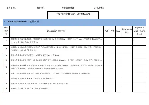
模具名称:模穴数: 型腔表面处理:产品材料:签名:年月日浇口及模胚制作参考标准常见浇口尺寸基本设计原则推荐如下:1。
点浇口:2. 扇形浇口:3。
潜伏式浇口:4。
边缘浇口:5。
凸耳浇口:W = 浇口宽度 ( mm )A = 型腔表面积 ( mm2 )n = 材料常数 material constant0.6 for PE, PS0.7 for POM, PC, PP6. 重叠式浇口:模架尺寸选择参考标准一、 注塑类模具镶块式模具的模架与镶件大小的选择,可参考下面的数据:图4—146 模架尺寸的确定“A"—表示镶件侧边到模板侧边的距离; “B"—表示定模镶件底部到定模板底面的距离;“C ”—表示动模镶件底部到动模板底面的距离; “D ”—表示产品到镶件侧边的距离;W=w= 浇口宽度 [mm]A= 型腔表面积[ mm 2]n= 材料常数0.6 for PE, PS0.7 for POM, PC , PP 0。
8 for CA, PMMA , PA“E”—表示产品最高点到镶件底部的距离;“H”—表示动模支承板的厚度(当模架为A型时) “X”-表示产品高度。
以上数据,仅作为一般性结构塑件摸架参考,对于特珠的塑件应注意以下几点:①当产品高度过高时(产品高度X≥D),应适当加大“D",加大值ΔD=(X—D)/2;②有时为了冷却水道的需要对镶件的尺寸做以调整,以达到较好冷却效果;③结构复杂需做特殊分型或顶出机构,或有侧向分型结构需做滑块时,应根据不同情况适当调整镶件和模架的大小以及各摸板厚度,以保证模架的强度。
④垫块高度的确定:垫块的高度应保证足够的顶出行程,然后留出一定的余量(5—10mm),以保证完全顶出时,⑤模架整体结构的确定:在基本选定模架之后,应对模架整体结构进行校核,看所确定的模架是否合适所选定或客户给定的注塑机,包括模架外形的大小、厚度、最大开模行程、顶出方式和顶出行程等,最后模架的整体尺寸以5mm为单位(例如计算所得模架尺寸为:232mm*253mm*186mm,那么实际应该取:235mm*255mm*190mm)。

Subject :一、(一).排位1.根据产品大小、结构等因素确定模穴,如1X1、1X2、1X3、1X4、1X8、1X16 等。
2.当几个产品出在同一套模具中时,考虑进胶的均匀性。
应将大的产品排在中间位置,小的产品置于两边。
3.当几个分型面不规则的产品在同一模具中时,排位必须充分考虑其分型面连接的顺畅。
4.一模多穴模具中,当有镶拼、行位等结构时,不得使其发生干涉。
5.排位时应综合模具每一方面,对流道,是否镶拼、行位、顶出、运水等结构要有一个全局性思考。
6.排位时以产品零线为定位基准。
当一模出一件时,可以考虑以产品对称方向外形分中。
(二)、模具系统设计【模具系统设计程序】浇注系统内模结构行位系统顶出系统冷却系统导向定位系统排气系统模胚结构件。
说明﹕在具体的模具设计过程中﹐不一定会严格遵守此程序﹐通常我们要返回上一步甚至上几步﹐修改部分数值﹐直至最后确认。
1﹑浇注系统浇注系统由主流道﹑分流道﹑冷料井和浇口等部分组成。
在设计浇注系统时,要考虑: 制品最主要的要求是什么?外观还是强度或是尺寸精度,找出最主要的矛盾,设计时,立足主要矛盾,同时,在不与主要矛盾发生冲突的前提下,改善其它次要矛盾,要做到进浇的均匀与顺畅。
1.1.主流道主流道一般为圆锥形,角度2~4o1.2.分流道1.2.1 .分流道的形状有圆形﹑梯形等几种,从减少压力和热量损失的角度来看, 圆形流道是最优越的流道形状。
当分型面是平面或者曲面时,一般采用圆形流道;细水口模,选用梯形流道,当流道只开在前模或者后模时,则选用梯形流道。
1.2.2.布置一模多腔的流道时,应充分考虑进浇的均匀性,尽可能做到平衡进浇。
1.2.3.设计分流道大小时,应充分考虑制品大小,、壁厚、材料流动性等因素,流动性不好的材料如PC料其流道应相应加大,并且分流道的截面尺寸一定要大于制品壁厚,同时应选适合成形品形状的流道长度。
流道长则温度降低明显,流道过短则剩余应力大,容易产生“喷池”,顶出也较困难。
模具设计细节要求一、 模具设计标准二、 模具进度追踪表三、 模具零件标准名称列表四、设计内容、程序及要求1、设计图档命名1.1 所有图档以模号(据新模确认单)命名。
1.2 涉及变更及修改的文件,以“模号+版本号(据改模确认单)”命名;版本号统一为字母A加改模次数。
相关修改应在2D图档中加以标示,标题栏中的命名也应一并修改。
2、设计文件管理示意图2.1 “drawing confirm”图纸确认管理示意图2.2 “design backup”设计备份管理示意图2.3“design share ”设计图档共享管理示意图2.4 “design inform 信息管理示意图ation ”设计相关3、设计要求3.1、新模:3.1.1接到新模信息后请根据设计标准及要求等,尽快制定出设计方案及绘制模具结构图发给我司确认,在图纸得到确认后应进行细节设计。
并在设计过程中请填写《模具设计进度追踪表》。
3.1.2在图面全部完成的情况下,应立即完成Bar List ;并拆出所有的EDM 图,并将其归入图档交给设计部。
3.2改模:收到改模的通知和信息制定改模方案及绘出图面发给客户确认。
图纸或尺寸有经修改,需在边框标题左上角修改表格中注明修改日期,并在后,请按要求在规定的时间内,N ”为被改次数,如:1、2、3……,在尺寸上或指出的位置标注时不可删除。
3.3存档的要求:3.3.份的图档需在CA 要运行“rge ”清除余的层、寸、块等。
如果还是发现图档依然很大(大于3M ),就需要“WBLock ”进行整个图档转存,同时再重新存档;如果文件还是很大,就没有别的办法。
在保存时要确保文件是版的格式。
3.3.2如是PRO —E 的图档,就需要在目录下运行“Purge3.4.1 在装配图上是要在具体的零件位置标识出“零件名称”,请用简略标识。
3.4.2所有图面(2D 与E “边框标题栏”请按我司的所提供的格式与要求。
3.4.3主要的n Cavity&Main Core 用A10规格来出图(除非镶件特别小可以用A3)。
模具设计作业标准及规范模具设计作业标准及规范二、2D模架设计1、产品的排位:影响排位的因素a产品的外形的结构b产品的进胶方式以及位置c 不同产品的分型面形状d产品的大小e产品的材料属性A、有无客户的排位要求判定所给定的排位与模具结构方面有无冲突B、排位时要注意的事项:产品的排位基准(一般以产品的最大外形进行XY向分中,以前后模分型面的某点为Z向基准),产品的缩水中心(一般以排位基准进行缩水,而不以模具中心或其它坐标进行缩水处理)产品的缩水率及缩水方式(缩水率由产品的材料以及成形压力决定——此数据由客户提供,缩水方式要与3D缩水方式一致,如:3D的比例缩水——2D的“SCALE”,3D的XYZ向的不同缩水——2D的“块的三方向的不同比例”处理)镜像处理问题(前后模正视图必须要注意镜像处理的问题:使用的是产品的投影视图需镜像,使用的是模仁的投影视图就不需镜像处理,前后模侧视图则无需镜像处理)顶针,运水,镶件,螺丝以及抽芯机构的大概位置、位移,排位的梳密要有设计余地流道的距离问题(在其它因素的治约下要尽可能使流道越短越好)不同产品的排位要求分型面整齐,减少起伏多变的台阶2、模仁大小的定义:影响因素:a产品的排位b产品在分型方向的投影面积c型腔的结构d钢料物理属性——钢度和硬度e成型注射时的最大压力A、有无客户对模仁的要求B、确定模仁大小时应注意的事项确保型腔壁有足够的厚度,不致于在加工时变形、成型时钢料变形影响成型尺寸精度、飞边,成型压力过大致使模仁断裂等。
(一般的常规参考数据:投影面积在50* 50——型腔壁厚约为25mm100*100——型腔壁厚约为30mm150*150——型腔壁厚约为33mm200*200——型腔壁厚约为40mm250*250——型腔壁厚约为43mm300*300——型腔壁厚约为50mm350*350——型腔壁厚约为55mm具体参数待查)确保在后期设计中排位有足够的位置,不致于多方面发生干涉而无法处理(如:水路与模仁固定螺丝相干涉;钢料厚度方向在精框中没了管位限制,则可适当加厚钢料等)。
Design Specifications 模具设计规范Contents1 General总则 (3)documents.设计文档 (3)2 Designdesignation模具标识 (4)3 Toolrepairs维护 (4)4 Facilitating5 Stocking of spare parts备品 (4)6 Tool retention device for progressive dies and transfer tools级进模和多工位模的固定装置 (5)7 Waste and finished parts slides / scrap metal separator废料和成品件滑槽/废料分离装置 (7)construction模具制造 (7)8 Toolbushes模钮 (10)9 Perforated10 Punches冲头 (11)punches落料冲头 (12)11 Blanking12 Material材料 (12)13 Markingdies字模 (14)14 Painting the tool模具涂装 (14)life模具寿命 (14)15 Tool16 Standards标准 (14)specifications送样规格 (15)17 Sampling1. General 总则The design specification is an integral part of the written ordering of tools for all future tool orders. Changes to or deviations from the items described here are subject to written approval from NEEF GmbH & Co. KG. In confirming the order, the manufacturer assumesresponsibility for the functionality of the tool, the dimensional accuracy of the part, compliance with the deadline and cost targets and the output.本设计规范为今后模具定购合同不可或缺的一部分。
设计合格的模具,需要从这里开始(模具设计规范)模具设计标准规范1A.通则1.使用FUTABA标准模座结构组模座。
2.使用正钢或同规格标准模具零件、配件。
3.所有导销(GUIDE PIN),衬套(BUSHING)必须在尾端有凸型。
4.所有模具设计图面纸张尺寸需统一使用全开规格尺寸,并等核准后,才开始制作。
5.模具上成品部分加工时,应以成品图中尺寸公差的半值来做为加工公差,不得使用成品图上之公差来加工。
6.所有度量单位以英制为准,长度使用毫米,重量使用公斤,温度使用摄氏(C)。
7.压力以英制PSI为单位,1PSI=1磅/平方英寸=14.2公斤/平方公分。
8.确认模厚,夹模板行程,顶出行程。
9.公母模四侧面吊模孔位置,“A”“B”板每一相邻两侧最少有一吊模孔,其他模板最少有一侧面有吊模孔。
10.四支导销中之任一支,必须做成偏心,即不与其他三支对称,以防止公、母模反向合模。
11.打印钢材规格及硬度於模仁底面。
12.详列材料表并标示材料与表面处理规格,并标示电热器瓦数规格与电压大小。
模具人杂志微信模具业第一微信13.打印,编号所有模具零件。
14.模具两侧面,应与装箱前以铁条固定,以免模面分开。
15.同一成品模穴超过一个穴时,应采用连续编号以便识别模穴。
16.在模座上需有一吊模孔於模具重心位置,以避免吊模时模具倾斜,并确定螺纹与深度足够负荷模重。
17.除模仁有大面积梯阶靠破外,均应装置模面锁定块(PARTING LINE LOCKS)。
18.肋片深度超过5mm时,需於肋底部加逸气销或以镶件制作,以利塑料充填。
19.以销子做平面靠破时,应将销子顶端加长伸入钢材内,避免销子顶面压损或变形。
20.成品重要处,应稍预留尺寸,避免加工尺寸过大而导致补焊。
21.模仁未经许可不准补焊。
22.在特殊情况下以补焊修补模具时,应选用模具同材料做焊条,以免材质不同影响成品之外观及留下痕迹。
23.各项装配组立均应确实控制公差,不得有敲击之痕迹留下。
模具设计的基本规范一、模前需进行设计检讨1.检讨成品与成品间相互配合之尺寸,(例如前后盖之配合)确定模具尺寸之公差带。
2.成品图中是否有铁别肉厚不平均之处,是否会造成缩水,建议客户修正。
3.PL线之确认,客户是否接受。
4.成品结构是否会造成模具强度脆弱,建议客户修正。
5.是否有填充不易处,建议客户修正。
6.入子接合线位臵,顶针位臵,客户是否接受。
7.如有加工困难,或无法加工者,需建议客户修正。
8.成品图中拔模斜度,尺寸之基准点确认。
9.塑胶材质,缩水率,金型取数,模具材质,成型机台之确定。
10.脱模斜度是否足够,(特别是咬花面及插破面)。
11.成品倒勾部分检讨使用何种结构,(滑块,斜顶等)确认结合线位臵。
12.成品有刻字部分确认字体、内容、位臵、尺寸(特别是凹字需注意)。
13.确认进料点之形式及尺寸。
二、模具图设计标准1.仔细研读成品图及开模检讨书。
2.成品图需加缩水,镜射后方可放入模具图中。
3.成品之基准,需标示在模具图上,并注明与模具中心的尺寸大小,(检查尺寸用)4.依据成品尺寸确认模仁及模座大小是否合适。
5.确认缩水率及塑胶材质是否正确。
6.模仁及模座之基准角度需标示且方向一致。
7.咬花面及光面,插破面之拔模斜度是否合理,(一般咬花至少2以上)8.成品尺寸单向公差需换算成中间尺寸。
9.POM材质,缩水率制作方式:芯型作22/1000,外型作18/1000,PL面及中心距离作20/1000。
10.模座吊环螺丝孔规格及尺寸需表示清楚(45以上模座,A、B板做四面吊环螺丝孔)11.螺丝孔之深度及规格需表示,并标示顺序号(如:S1、S2……)。
12.水孔流动路线需表示清楚,水孔间最佳距离(50mm),离PL面或成品以(15mm-20mm)为佳。
注意检查水孔,“O”型环是否与顶针,螺丝、入子碰穿。
13.水孔堵头尺寸不能太短(配合铜塞尺寸)。
14.水孔需编号,直径及水管牙需标示(例1#IN,1#OUT,1/8PT,1/4PT)。
模具设计规范1.目的:为达成冲模设计、加工准确、通用,快速之目的,确保模具及样品品质,提高生产效率。
2.范围:适用于在厂内自行开发产品及客户委托设计的模具设计。
3.定义:3.1冲压模具:利用其生产五金等冲压产品,适用于冲压机生产用的模具。
4.权责:权责内容详见模具设计流程图(请参考附件一)5.作业流程:5.1模具设计流程图(请参考附件一)6.作业说明:档名前加模具编号,如XXXXX-L01A,共用模用B表示,则在第一套完整图号后加互换产品之展开图,料带图。
互换之零件等,编号为XXXXXB-L01A。
XXXXXB-03等;复制模用N表示,若有多套,分别用N1,N2,N3。
标件图为最后一张即第y张。
<图号>,<档名>统一。
建议:整套模具只能有一个总图,总图用XXXXX-ALL命名,所有图档都在总图里完成,确认无误后存出,尽量保持总图为最新版本。
注:除客户要求外,模具模号一般以产品料号为准。
注:模板素材尺寸公差为+0.3~+0.5 6.3.标(零)件及配合注:一般五金配件以伍全公司目录为标准。
*1。
下模入子刀口到边距离>/=4.0;建议下模入子比脱板入子单边大 1.0导料板>0.5,脱板入子不用避位。
*2。
端子类刀口用两段式(8+17),上8.0用WC,下用SKD11,冲子用WC,刀口直线位1.5斜1.0度落屑对于特别小的冲子,刀口可直线位0.0斜0.2度落屑。
*3。
脱板入子挂肩均统一为4.0。
*4。
入子大小不得小余4*5(过小不便于加垫片或敲出)。
*5。
零件之间滑动要求时,一定要放单边间隙,一般为0.01。
*6。
敲击孔模座统一钻Φ5.0,垫板钻Φ3.5,特殊情况允许钻或割Φ2.1。
*7。
对于铁壳或铜壳,刀口做整体式,冲子刀口材料用SKD11/SKH9/ASP23 HRC62,脱板刀口入子,及夹板入子浮升块用SKD11;成形冲子入子均用SKD11/SKH9/ASP23。
6.4.作图规范6.4.1.颜色:除虚线.中心线等特殊线为便在打印时以区别其粗细外,其余线均以随图层决定颜色,标注线之文字与指引线用绿颜色.当正式出图时,除标注.虚线.中心线等特殊线外,其余全部随图层色,图档设变时,将设变部位用其它颜色区分开来。
Mold Design Specifications Note: This mold design specification document is meant to serveas a guide to requirements for molding tools operated at CommScope Omaha. However, not all jobs will have the same requirements and so it is understood that each job will be accompanied with a mold design specification individuallymarked by the product engineer reflecting the specificrequirements of his job. All requirements will apply unless specifically deleted by the product engineer.CommScope Mold planning Worksheet 12000 I st.Omaha, NE 68137Engineer Try out to be performed at Comm Vendor phone # * Capability Study required yes noFax # * First article inspection required yes noE-Mail SLA Model Available yes no Description / part name Proto Type Part yes no Piece Part Comcode # Tool Design available yes no Tool # / CT- XXOHXXXXPurchase Order No. * Refer to 8.1 & 8.2 mold spec.Delivery RequirementRaw Material / PlasticMold Cavities RequiredEstimated cycle timeUG or Pro - E Rev #H frame inserts Other FinishCOMMSCOPE - OMAHAISSUE 31 E-7251 1/04/99The tool shall be designed for full automatic operation.1.0 Mold bases / Mold Component Steels:1.1Unless otherwise specified, small (<1.5" square) cores and cavity details subject to seal-off shall be constructed of AISI S-7 steel,hardened to Rc:54-56. Larger cores and cavities shall be constructed of AISI H-13 steel, hardened to Rc 52-54. Either detail is tohave an equivalent Charmiles Std. EDM Finish No. 24, polished to facilitate parts removal.Note:If the material to be molded is corrosive, such as polyvinyl chloride (PVC) or polyphenylene sulfide (PPS or Ryton), the coresand cavities shall be Armco 17-4-PH from Armco Steel Corp., hardened to 44 R.C., or Type 440C, hardened and finished as above.Cavities shall not be machined directly into the mold plates.1.2Unless otherwise specified, cavity retainer sets ("A" & "B" Plates) shall be constructed of 4130 (DME #2) steel, 280 - 320 BHN. or AISI H-13 steel, hardened to 40-45 RC.Note: If the material to be molded is corrosive, the cavity retainer set ("A" & "B" Plates) shall be Type 420 stainless steel, hardened and finished as above.1.3Cam-actuated slide details, if required shall be constructed of AISI*H-13steel, hardened to Rc:52-54 with a Charmiles Std. EDMFinish No. 24, polished to facilitate parts removal.Note: If the material to be molded is corrosive, the slide details shall be Type 440a stainless steel, hardened and finished as above. 1.4If a stripper ("C") plate is required, it shall be constructed of AISI A6 steel, hardened to RC:54-56.Note: If the material to be molded is corrosive, the stripper plate shall be type 440C stainless steel, hardened to RC:54-561.5All other mold plates (base, ejector pin retainer, back-up plates, ejector housing, etc.) shall be constructed of AISI4140 steel, pre-hardened to a minimum of 300 BHN.1.6If the material to be molded is corrosive, sprue bushing and runner system shall be constructed of Type 420 stainless steel. Otherwise, standard sprue bushings shall be used. All sprue bushings shall be polished.1.7Standardized mounting plates shall be AISI Type 41534, 300BH.Natalloy 2H or equivalent.Note: S-7 tool steel - oil quench section sizes over 1-1/2 thick.1.8Female side locks should be embedded in the movable half of the mold. The preferred type locks are the DME straight side interlocks or equivalent. If stripper plate design is applicable use DME X - style straight side interlocks or equivalent.1.9Components such as core pins, ejector pins, leader pins and bushings, etc. shall be standard off-the-shelf items wherever possiblewith the supplier for each component listed on the drawing stock list.1.10All exterior edges are to be broken approximately 1/16 by 45 degrees1.11Leader pin lengths to engage a minimum of ½” before force and cavity engagement, and ¼” before angle pins.1.12Pry bar slots ¼” deep to be provided in all four corners of mold plates on parting line. Leader pin bushings must be adequatelyvented through lower plate to allow air and debris to escape as pin enters.1.13Provide safety strap connecting A and B plates on top side of mold; strap to remain with tool. On runnerless tools, a strap will beprovided to separate the mold plates for purging.1.14The following information (shall be stamped on the tool.)•CommScope Tool No. Ct- (Refer to mold planning work sheet.)•description - (Refer to mold planning work sheet.)•weight - (To be determined by tool builder)•piece part cc# - (Refer to mold planning work sheet.)To be stamped in 1/4 to 3/8-inch characters on the “operator viewed” side of tool.1.15The mold nozzle seat shall be 3/4" spherical radius.1.16Eyebolt holes shall be provided on all 4 sides of each major component plates. Major component plates include: "A" plate, "B" plate, clamp plate, support plate, ejector housing, manifold housing (hot runner tools) and stripper plates.•Use: 1/2 - 13 = up to 300 lbs. total tool weight.•3/4 - 10 = from 300 to 2500 lbs. 1 - 8 = over 2500 lbs.1.17All conventional runner multi cavity tools shall be designed with runner shut offs which can be activated without removing the toolfrom the press. DME runner shut off inserts or equivalent to be used on both A & B side of tool . ( part # MRS - 0013 thru 00261.18Ejector return pins shall not lie within the path of falling, ejected parts2.0 Mold Design2.1Drawings, Manual design or Cad designs will be completely detailed and dimensioned. All designs will have all details called out on the main plan stack up views. A bill of material with complete component specifications will be included2.2Shrinkage allowance shall be determined by the tool manufacturer, and noted on the preliminary drawings.2.3General arrangement and cavity details of proposed design shall be submitted for COMMSCOPE Engineering approval prior tocutting metal for the mold. This approval is for general arrangement only. Any exceptions to this specification should be noted onthe quotations.Note: ELECTRONIC DRAFTING:E.D.S. U.G.-II version 13 or later. or P.T.C. Pro-Engineer version 18or later. Drawing procedures are available at the Omaha; however, if neither system is available, contact Harvey Ma rx’s in MoldDesign. Department JT11A1200 for instructions. Data may be exchanged through magnetic storage media or via modem. QIC-150,3.5 inch diskette and TCP/IP Network transmission could be used in these instances.2.4Final design information in complete detail on paper shall be furnished, after approval of samples by COMMSCOPE . These tracings will be made in accordance with COMMSCOPE COMMUNICATION (Omaha) Tool and Gage Drafting Standards Spec. SU-316dated12-14-98. For databases please refer to preceding note.2.6A standard numbering system will be followed on all multi-cavity tools. The cavity numbering system will be to start with the upperleft hand corner of the injection half of the tool as it will hang in the molding press and proceed in a counterclockwise rotation. The identification should include both a letter and number to completely identify the part. The cavity numbering system should coincide with and runnerless wiring layout.2.7Tool prints shall have tie bar location drawn both on preliminary and final designs.3.0 Tolerances3.1Tool shall be designed to nominal part dimensions, not to high side of tolerance.3.2All part projections, such as locking tabs, feet, etc. which must be ejected from a cavity shall be designed with 1/2 deg. (min.) which must angle unless otherwise specified on the piece part drawing.3.3All tool drawings shall contain a tolerance box to read:Four-Place Dec.= +/-.0005Three-Place Dec.= +/-.001Two-Place Dec.= +/- .01One-Place Dec.= +/-.05Dimensions requiring a tighter tolerance shall be notedindividually.Note: All dimensions shall be tolerance such that all same parts are completely interchangeable; any dimension not -tolerance shall be box tolerance.4.0 Cavities4.1Highly-detailed, close-tolerance cavities shall be constructed in segments, including end segments and center segments, the number of the latter to be determined by the length of the parts.4.2If cam-actuated details are required, the following designs shall apply:•Slide wear surfaces shall be hardened to RC-54-56.• Tool shall be designed so that slides can be removed without removing the tool from the press.• Hydraulic core pull shall not be used without written engineering approval.•Slides are to run horizontally in the tool as it hangs in the press . the slides must have spring forced retention.4.3All cavity, core and slide details shall be Armoloy or chrome plated with .000050/.000075 thickbuild-up per side on all surfaces with no edge build-up. All detail dimensions shall be designed to allow for this plating build-up.Note: Any areas which will not allow chrome plating shall be specified on the detail print as a "restricted area" not to be plated. Any cavity, core, or slide detail which is not chrome plated shall require previous written CommScope Engineering approval.Approved source: Armoloy of Illinois, 118 Simonds Avenue, DeKalb, IL 60115 Attention: Jerome Bejbl ph # 1-815-758-66914.5All E.D.M. surfaces shall be retempered after final machining at 50 deg. F to 100 deg. F under the original tempering temperature to minimize any untempered martensitic surface layer formed during the E.D.M.process.4.6Details will be stamped or etched with detail number and type of steel.4.7Scissors / Bypass shut-offs are to be a minimum 5 degree angle unless otherwise approved.4.8Spare details shall be provided equivalent to 25% of the total required for a complete tool. Spare details will be provided to replace one of each of the details which are deemed vulnerable to short-term damage. Spares will becoated and ready for installation into any cavity.4.9Cooling lines shall be located as close to cavities and runners as possible and shall be labeled "IN or OUT" as required. Lines shall be recessed for flush mounting DME "Jiffy-Tite" plugs or stand-off legs provided. “Jiffy-Tite plugs,1/4”NPT, 3/8” thru hole, DME part no. JP352 or JP352F shall be installed in all cooling line openings. All water lines should enter and exit the bottom of the tool with no water connection on the top of the tool ,If it is required to have multiple waterlines a manifold for the "A" and "B" mold halvesshall be provided. The manifolds shall be either mounted to the standardized clamp plates or incorporated into the tool.The manifold shall have a single inlet and outlet per CITCO Products Inc. (North 8779, Highway X, Watertown, Wisc. 53094) or equivalent. 5.0 Venting5.1Vents will have a relief .030 deep extending .100 - .125 from the edge of the cavity to out side of the mold. Vent width to be 1/8” - 1/2” wide depending on part size and material to be molded. The distance from the end of t he relief to the cavity will be the effective vent depth.5.2All vents to be draw stoned to ensure self cleaning.Provide ejector pins or inserts in deep pockets and rib areas for venting purposes as necessary.5.3Runner system to be vented.6.0 Ejector Systems6.1If the part design required multiple thin-walled sections, two-stage ejection shall be used. As an example, the cores may be ejected first, clearing the parts from the cavities, and the part subsequently ejected from the cores.6.2Guided ejector systems shall be used wherever possible.•Ejector plates shall have a minimum of four guide posts and four return pins.•Guide posts must be secured to the clamp plate and not telescoped into or attached to the cavity plate.6.3A micro switch shall be mounted between the ejector housing and ejector plate to verify the ejector pins are in the full returnedposition before allowing the molding press to close. Switch to be used is "MICRO SWITCH" 1CH32-R6.4Ejector plate shall use die spring return and spring ratings shall be specified on drawings.6.5Ejector plate stop pins (DME or National) shall be provided.6.6Unless otherwise specified, standard SPI knockout pattern shall be provided.6.7Ejector guide post bushings shall be Lamina bronze or equivalent. (DME standard leader pins and guided ejector bushing series.) 6.8All ejector plates shall be provided with hardened riser pads. They shall be mounted to the ejectorplate for the purpose of maintaining a standardized clearance of .050" from the ejector pad to the back of the "B" clamping plate.This is to allow COMMSCOPE to standardize the molding press K.O. rods.6.9All tools using a submarine gate shall also be designed with a ejector pin adjacent to / or as close to the gate as possible to eject any partial shot without damaging the tool.7.0 Hot Runners7.1All runnerless tools shall be designed to provide the ability to purge through the hot runner system by separating the cavity retainer plate from the hot manifold while in the molding press.7.2All tools equipped with a hot sprue bushing shall use a 115 volt controller.7.3Thermoplastic hot runner will have an insulator sheet mounted to the stationary side clamp ½ “ thic k and parallel with in .002. DME High Temperature Insulator sheets or equivalent.7.4Final design information in complete detail on paper and cad shall be furnished, after approval of samples by COMMSCOPE .These tracings will be made in accordance with COMMSCOPE (Omaha) Tool and Gage Drafting Standards Spec. SU-316 issue 2dated 2-19-967.5All runnerless tool drawings shall include a complete wiring diagram similar to CT-80OH3109, sheet 47. The diagram is to includea complete bill of materials. With D.M.E./Moldmaster/Husky type runnerless tools use the following DME catalog number electricalplugs:Power: PIC-12-G Thermocouple: MTC-12-G Terminal mounting box: PTC-12-TB-G8.0 Sampling and Inspection of Mold / Process Capability8.1The completed mold shall be sampled by the tool manufacturer and samples from each cavity shall be produced. Samples submitted to COMMSCOPE Engineering for approval shall be obtained during this continuous run, which shall duplicate normal productioncycles as determined and observed by COMMSCOPE Engineering. Parts shall be taken from consecutive shots during the run and tagged or numbered in the order in which they were produced.8.2The tool manufacturer shall furnish inspection data certifying that sample parts meet the part drawing requirements. Final acceptance of the mold will be based upon the conformance of molded parts from each cavity to the part requirements.8.3Any parts produced in advance of sample approval by COMMSCOPE Engineering shall be the responsibility of the tool manufacturer.8.4The tool shall be observed in operation by COMMSCOPE Engineering and/or Purchasing personnel at the tool manufacturer's plant.8.5COMMSCOPE is to supply plastic (no charge) unless otherwise specified in the purchase order.8.6Try outs that are performed @ the tool vendors will be required to supply the molding engineer with complete sample shots including runner (quantity to be determined by molding engineer). Also there shall be a sample that is a fill only shot that is approximately 95% to 99% full at the last place to fill. This will serve as an indication of runner balance and mold pressure transducer location.9.0 Other Information9.1The tool shall not be shipped without written approval by COMMSCOPE (Omaha) Purchasing Department.9.2The attachment pertaining to patents and technical information shall apply.9.3The mold maker is responsible for:•Insuring that mold conforms to specifications supplied by CommScope•Utilizing sound tool practices in the construction of the mold.•seek prior approval for non - desirable practices. (shim, weld, etc.)•Meeting promised completion dates.9.4The following has been adopted from the society of plastic engineers mold classification system and is used in reference to mold life and warranties . Actual mold construction details will be specified on the mold engineering planning worksheet.9.5The following document is a new tool check list that is required to be completed and returned to CommScope molding engineersdepartment at completion of mold building project.New Tool Check ListN/A OKVerify tool ID stamped on mold base CT_ _ OH _ _ _ _Verify sprue bushing spherical radius to equal ¾”.Verify gate size is indeed what final tool prints call-out.Verify all gate sizes on multi-cavity tools do not vary more than .001”.Verify all water passages have been pressure tested @ > 80 psi.Verify mold base water inlets have been recessed on bottom of tool to accept 200 series JiffyTight fittings.Verify safety strap has been provided and stamped same as mold base.Verify Cavity ID has been engraved on each individual cavity / ejector pin per mold designspecs.Verify mold transducer slot has been included.Verify transducer ejector pin size stamped on mold base.Verify tool switch components have been attached to mold base topside and offset to avoidinterference of eyebolts / hoist rings.Verify transducer slot is on topside of tool unless otherwise specified.Verify latest mold design has been electronically transferred with hard copy to follow.Verify molding tool has been sprayed and secured for shipment (¾” plywood box and skid).Verify company logo “CommScope” to be engraved on removable tool detail inse rt.Tool # / Mold ID: CT-___________________________________Description: ________________________________________________Toolmaker Initials: ______________________________________Date Approved: ________________________________________Two Copies Needed!One copy of this checklist shall be transported with the tool in crate.(Should not be included in the packing list!).The second copy will need to be faxed to CommScope engineering 402-691-3465.。