艾默生无线网关中文说明书(Gateway_CA)
- 格式:pdf
- 大小:3.02 MB
- 文档页数:66
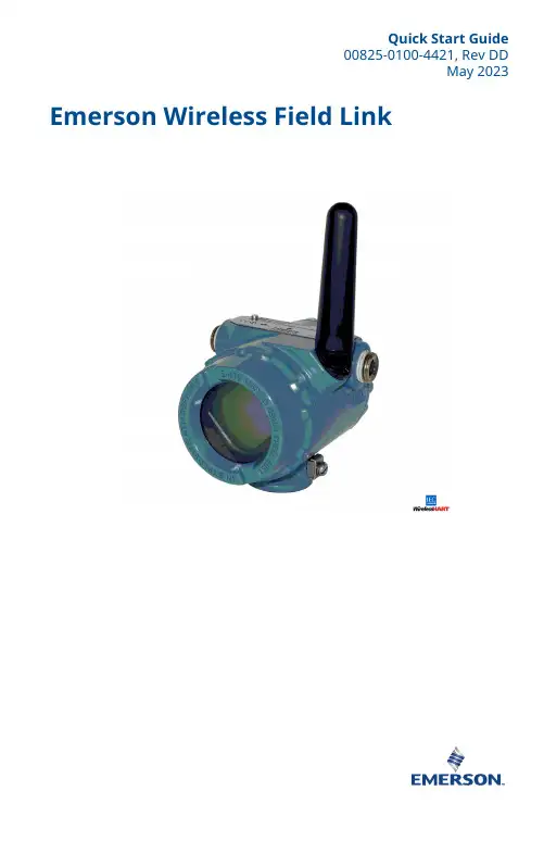
Quick Start Guide00825-0100-4421, Rev DDMay 2023 Emerson Wireless Field LinkQuick Start Guide May 2023This guide provides basic guidelines for the Emerson Wireless Field Link. It does not provide instructions for diagnostics, maintenance, service, or troubleshooting. This guide is alsoavailable electronically on .WARNINGFailure to follow these installation guidelines could result in death or serious injury.Ensure only qualified personnel perform the installation.Explosions could result in death or serious injury.Installation of the transmitters in a hazardous environment must be in accordance with the appropriate local, national, and international standards, codes, and practices. Kindly review the Product Certifications section for any restrictions associated with a safe installation.Electrical shock could cause death or serious injury.Avoid contact with the leads and terminals. High voltage that may be present on leads cancause electrical shock.This device complies with Part 15 of the FCC Rules. Operation is subject to the following conditions:This device may not cause harmful interference.This device must accept any interference received, including interference that may causeundesired operation.This device must be installed to ensure a minimum antenna separation distance of 8-in. (20 cm) from all persons.ContentsWireless considerations (3)Physical installation (6)Verify operation (8)Reference information (9)Declaration of Conformity (11)Product certifications (14)/Rosemount1 Wireless considerations1.1 Power up sequenceTo achieve a simpler and faster network installation, verify thefollowing before the power modules are installed in any wireless fielddevices:•Emerson Wireless Field Link is installed and functioning properly•Wireless I/O is installed and functioning properly•Beginning with the closest, wireless field devices are powered upin order of proximity to the Wireless Field Link1.2 Mounting locationMount the Wireless Field Link in a location that allows convenientaccess to the host system network (wireless I/O) as well as thewireless field device network.Find a location where the Wireless Field Link has optimal wirelessperformance. Ideally this will be 15 to 25 ft. (4,6 to 7,6 m) above theground or 6 ft. (2 m) above obstructions or major infrastructure.A Control roomB GroundC Field linkD Mast or pipeE InfrastructureMay 2023Quick Start Guide Quick Start Guide3Quick Start Guide May 2023 1.3 Antenna positionPosition the antenna vertically, either straight up or straight down.Verify a distance of at least 3 ft. (1 m) is maintained from anylarge structure, building, or conductive surface to allow for clearcommunication to other devices.Figure 1-2: Antenna Position1.4 Conduit plugReplace the temporary orange plugs with the included conduit plugsusing approved thread sealant.Figure 1-3: Conduit PlugsAAA Conduit plug/Rosemount1.5 Intended useThe Wireless Field Link must be used in conjunction with a networkmanager or network Gateway. The Wireless Field Link then functionsas a translator between the wired network and a wireless fieldnetwork.Figure 1-4: Example System ArchitectureABC DEFA Host systemB Control networkC Network managerD Field linkE Wireless field networkF Wireless field devicesMay 2023Quick Start Guide Quick Start Guide5Quick Start Guide May 2023 2 Physical installation2.1 Pipe mountingProcedure1.Insert larger U-bolt around 2-in. pipe/mast, through thesaddle, through the L-shaped bracket, and through the washerplate.e a 1/2-in. socket-head wrench to fasten the nuts to theU-bolt.3.Insert smaller U-bolt around base the Wireless Field Link andthrough the L-shaped bracket.e a 1/2-in. socket-head wrench to fasten the nuts to theU-bolt.Figure 2-1: Mounting2.2 Power and data wiringWARNINGThe 781 Wireless Field Link data communication terminals A (+) and B(-) must never be connected directly to a power supply. Doing so maydamage the device.After removing the terminal block cover, the communicationterminals (Data A and Data B) are on the left side of the terminalblock. Connecting these terminals to anything other than thecorresponding data terminals of the 1410S or 1410D Gateway maydamage the 781 Wireless Field Link.Procedure1.Remove housing cover labeled “Field Terminals.”/Rosemount2.Connect the positive power lead to the “+” power terminal and the negative power lead to the “–” terminal.3.Connect the Data + lead to the “A (+)” terminal and the Data –lead to the “B (–)” terminal.4.Plug and seal any unused conduit connections.5.Replace the housing cover.Figure 2-2: Emerson Wireless Field Link Terminal DiagramABCD2.3 GroundingGround the Wireless Field Link enclosure in accordance with national and local electrical codes. The most effective grounding method is a direct connection to earth ground with minimal impedance. Ground the Wireless Field Link by connecting the external ground lug to earth ground. The connection should be 1 Ω or less.May 2023Quick Start GuideQuick Start Guide 7Quick Start Guide May 2023 3 Verify operation3.1 Power-up sequenceUpon applying power to the Wireless Field link the LCD display meterwill activate and display a series of startup screen. The followingscreens are displayed during startup:1.Startup Screen 1 – All segments on2.Startup Screen 2 – Device identification3.Startup Screen 3 – Tag4.Startup Screen 4 – Status3.2 Normal operationAfter the initial startup screens are displayed, the Wireless Field Linkwill cycle through the following periodic screens:1.Electronics Temperature Screen2.Percent Range Screen3.Wired Interface Usage4.Radio Interface UsageThe Wireless Field Link continues to rotate through each periodicscreen through the course of normal operation. If any diagnosticor fault condition occurs, a corresponding diagnostics screen willappear./Rosemount4 Reference informationFigure 4-1: Emerson Wireless Field Link Terminal DiagramABCDNoteThe Emerson Wireless Field Link requires separate twisted shield pairs (four wires) for power and data.May 2023Quick Start GuideQuick Start Guide 9Quick Start Guide May 2023 Figure 4-2: Emerson Wireless Field Link Dimensional DrawingTable 4-1: Emerson Wireless Field Link Specificationsabove maximum ambient temperature./Rosemount5 Declaration of ConformityMay 2023Quick Start GuideQuick Start Guide 11Quick Start Guide May 2023/RosemountMay 2023Quick Start GuideQuick Start Guide13Quick Start Guide May 2023 6 Product certificationsRev 2.36.1 European Directive InformationA copy of the EU Declaration of Conformity can be found at theend of the Quick Start Guide. The most recent revision of the EUDeclaration of Conformity can be found at .6.2 Ordinary Location CertificationAs standard, the transmitter has been examined and tested todetermine that the design meets the basic electrical, mechanical,and fire protection requirements by a nationally recognized testlaboratory (NRTL) as accredited by the Federal Occupational Safetyand Health Administration (OSHA).6.3 Installing in North AmericaThe US National Electrical Code® (NEC) and the Canadian ElectricalCode (CEC) permit the use of Division marked equipment in Zonesand Zone marked equipment in Divisions. The markings must besuitable for the area classification, gas, and temperature class. Thisinformation is clearly defined in the respective codes.6.4 USAI5 USA Intrinsic SafetyCertificate80011697Markings Class I, II, III Division 1 Groups A, B, C, D, E, F, G T4; ClassI, II, III Division 2, Groups A, B, C, D, F, G T4 T4(-40 °C ≤ T a≤ +70 °C); Class I Zone 0, AEx ia IIC T4 Ga; Class I Zone 2,AEx ic IIC T4 Gc; Zone 21 AEx ia IIIC T90 °C Db; Zone 22AEx ic IIIC T90 °C DcStandards FM 3600:2011, FM 3610:2018, FM 3611:2018, ANSI/UL60079-0:2019, ANSI/UL 60079-11:2014Warnings/Conditions of Acceptability1.Installed as per. Control drawing 01410-1300 for Hazardousand Non-Hazardous areas.2.Must be installed with a Resistive Barrier./RosemountMay 2023Quick Start Guide3.The plastic enclosure may constitute a potential electrostaticignition risk and must not be rubbed or cleaned with a drycloth.4.The measured capacitance between the equipment enclosureand metallic conduit adapter is 21pF. This must be consideredonly when the Model 781S is integrated into a system wherethe process connection is not grounded.6.5 CanadaI1 Canada Intrinsic SafetyCertificate80011697Markings Class I, II, III Division 1 Groups A, B, C, D, E, F, G T4; ClassI, II, III Division 2, Groups A, B, C, D, F, G T4 T4(-40 °C ≤ T a≤ +70 °C); Ex ia IIC T4 Ga; Ex ic IIC T4 Gc; Ex ia IIIC T90 °CDb; Ex ic IIIC T90 °C DcStandards CAN/CSA C22.2 No 60079-0:2019, CAN/CSA C22.2 No.60079-11:2014, CSA C22.2 No.213 – 2017Warnings1.Installed as per. Control drawing 01410-1300 for Hazardousand Non-Hazardous areas.2.Must be installed with a Resistive Barrier.3.The plastic enclosure may constitute a potential electrostaticignition risk and must not be rubbed or cleaned with a drycloth.4.The measured capacitance between the equipment enclosureand metallic conduit adapter is 21pF. This must be consideredonly when the Model 781S is integrated into a system wherethe process connection is not grounded.6.6 EuropeI1 ATEX Intrinsic SafetyCertificate Baseefa11ATEX0059XStandards EN IEC 60079-0:2018, EN 60079-11: 2012Markings II 1 G Ex ia IIC T4 Ga, T4(–40 °C ≤ T a≤ +70 °C)Quick Start Guide May 2023Special Conditions for Safe Use (X)1.The plastic antenna may present a potential electrostaticignition hazard and must not be rubbed or cleaned with a drycloth.2.The Rosemount 781 enclosure is made of aluminum alloy andgiven a protective paint finish; however, care should be takento protect it from impact or abrasion if located in a zone 0environment.3.The apparatus is not capable of withstanding the 500 Visolation test required by EN 60079-11. This must be taken intoaccount when installing the apparatus.6.7 InternationalI7 IECEx Intrinsic SafetyCertificate IECEx BAS 11.0028XStandards IEC 60079-0: 2011, IEC 60079-11: 2011Markings Ex ia IIC T4 Ga, T4(–40 °C ≤ T a≤ +70 °C)Special Conditions for Safe Use (X)1.The plastic antenna may present a potential electrostaticignition hazard and must not be rubbed or cleaned with a drycloth./RosemountMay 2023Quick Start Guide2.The Rosemount 781 enclosure is made of aluminum alloy andgiven a protective paint finish; however, care should be takento protect it from impact or abrasion if located in a zone 0environment3.The apparatus is not capable of withstanding the 500 Visolation test required by EN 60079-11. This must be taken intoaccount when installing the apparatus.6.8 EAC – Belarus, Kazakhstan, RussiaIM (EAC) Intrinsic SafetyCertificate RU C-US.Gb05.B.00643Markings0Ex ia IIC T4 Ga XSpecial Conditions for Safe Use (X)1.See certificate for special conditions.6.9 JapanI4 CML Intrinsic SafetyCertificate CML20JPN2401XMarkings Ex ia IIC T4 Ga (-40 °C ≤ T a≤ +70 °C), Ex ic IIC T4 Gc (-40°C ≤ T a≤ +70 °C)Special Conditions for Safe Use (X)See certificate.6.10 BrazilI2 INMETRO Intrinsic Safety (Rev 1 Only)Certificate UL-BR 20.1568XQuick Start Guide17Quick Start Guide May 2023 Markings Ex ia IIC T4 Ga (-40 °C ≤ T a≤ +70 °C), Ex ic IIC T4 Gc (-40°C ≤ T a≤ +70 °C)Standards ABNT NBR IEC 60079-0:2013, ABNT NBR IEC60079-11:2013Special Conditions for Safe Use (X)See certificate.6.11 ChinaI3 NEPSI本质安全证书GYJ20.1394X(CCC 认证)所用标准GB3836.1 – 2010, GB3836.4 – 2010, GB3836.20-2010标志Ex ia IIC T4 Ga特殊使用条件(X)1.产品外壳含有轻金属,用于0区时需注意防止由于冲击或摩擦产生的点燃危险。
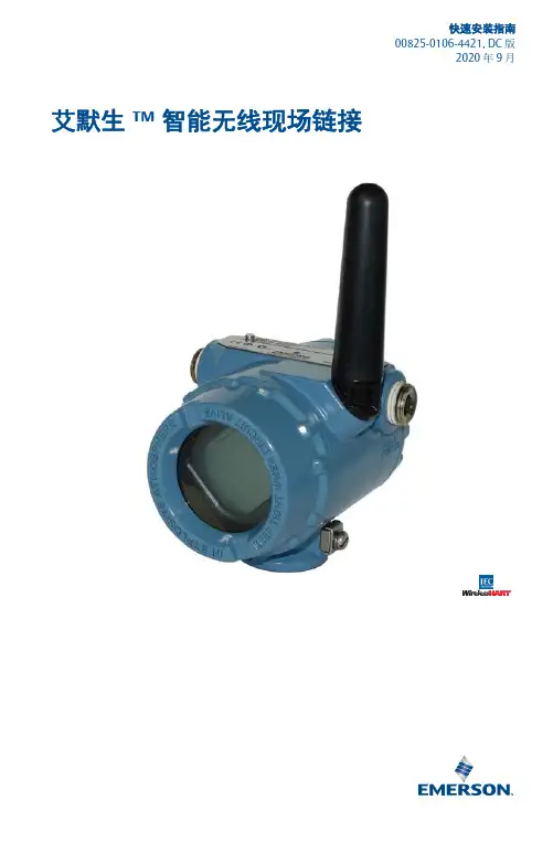
快速安装指南00825-0106-4421, D C版2020年9月艾默生™智能无线现场链接2020 年 9 月2快速安装指南本指南提供智能无线现场连接的基本安装说明,不提供诊断、维护、检修或故障排查的说明。
本指南的电子版本也可从 获得。
警告不遵守这些安装准则可能会导致严重的人身伤害甚至死亡。
⏹确保仅由取得相关资质的人员进行安装。
爆炸可能会导致死亡或严重伤害。
⏹在易爆环境中安装本变送器时,请务必遵守适用的当地、国家和国际标准、规范及规程。
请核对产品证书一节中是否有与安全安装相关的任何限制。
触电可能会导致死亡或严重伤害。
⏹应避免接触引线或接线端子。
导线上可能存在的高电压会造成电击。
本设备符合 FCC 规范的第 15 部分的规定。
设备操作应符合下列条件:⏹本设备不会导致有害干扰。
⏹本设备必须接受任何接收到的干扰,包括可能会导致非预定操作的干扰。
⏹安装本设备时,必须确保天线与所有人员间的最小间隔距离为 20 厘米 (8 英寸)。
目录无线设备安装注意事项 . . . . . . . . . . . . . . . . . . . . . . . . . . . . . . . . . . . . . . . . . . . . . . . . . . . . . . 3物理安装 . . . . . . . . . . . . . . . . . . . . . . . . . . . . . . . . . . . . . . . . . . . . . . . . . . . . . . . . . . . . . . . . . . . 5验证操作 . . . . . . . . . . . . . . . . . . . . . . . . . . . . . . . . . . . . . . . . . . . . . . . . . . . . . . . . . . . . . . . . . . . 7参考信息 . . . . . . . . . . . . . . . . . . . . . . . . . . . . . . . . . . . . . . . . . . . . . . . . . . . . . . . . . . . . . . . . . . . 8订购信息 . . . . . . . . . . . . . . . . . . . . . . . . . . . . . . . . . . . . . . . . . . . . . . . . . . . . . . . . . . . . . . . . . . 10产品认证 . . . . . . . . . . . . . . . . . . . . . . . . . . . . . . . . . . . . . . . . . . . . . . . . . . . . . . . . . . . . . . . . . . 11快速安装指南32020 年 9 月无线设备安装注意事项上电次序在任何无线现场设备中安装电源模块之前,应安装好智能无线现场链接和无线 I/O ,并确保它们能正常工作。

快速安装指南00825-0106-4541, Rev DE3 月年 2020 年月艾默生 Plantweb™ Insight快速安装指南 3 月年 2020 年月内容概述 (3)系统要求 (4)安装 (6)启动应用程序 (9)自定义系统设置 (10)应用程序安装 (13)应用程序配置 (14)/Rosemount3 月年 2020 年月快速安装指南1概述感谢您选择 PlantwebInsight。
本文档将引导您完成软件平台的初始设置。
要了解特定应用程序的更多详情和配置信息,请参阅《Plantweb Insight 参考手册》。
安装 Plantweb Insight 之前,确保您已设置并正确运行所需的虚拟化软件/管理程序。
本文档的系统要求部分列出了兼容的虚拟化软件/管理程序。
快速安装指南3快速安装指南 3 月年 2020 年月2系统要求Plantweb Insight 提供时是一套完全开发的虚拟机(例如 .ova 文件)。
用户将收到完整的虚拟机镜像,以便安装在用户提供的虚拟软件或管理程序内。
Plantweb Insight 虚拟机包含一个 web 服务器,任何 web 客户端都可以通过网络访问该服务器。
所有配置和虚拟化均通过 web 浏览器用户界面完成。
Plantweb Insight 可安装在网络服务器上或 PC/笔记本电脑上。
两种安装方案的要求和安装步骤相同。
网络连接可根据机构的政策设置。
任何相关的网关都必须能够在网络上访问。
开始之前,验证您的系统符合最低要求。
2.1主机操作系统虚拟化软件/管理程序•VMware Workstation Pro™ 10 或更高版本(您可在此处查看要求)•VMware vSphere® 5.5 或更高版本(您可在此处查看要求)或•如果您在使用其他的虚拟化软件 (Microsoft® Hyper-V®),请联系Rosemount™支持人员2.2访客操作系统•处理器 = 4•内存 = 至少 16 GB RAM•硬盘驱动器 = 100 GB 可用空间2.3应用浏览器(支持最新版本)•Chrome™浏览器•Microsoft Internet Explorer®/Rosemount3 月年 2020 年月快速安装指南2.4其他要求•安装时需要使用 DVD 驱动器•需要使用 DHCP 服务器分配有效的 IP 地址(连接到 Plantweb Insight Web 界面之后,即可配置静态 IP 地址)2.5网关兼容性Plantweb Insight 与固件版本为 4.7.68 或更高的 Emerson 无线 1410/1420网关兼容。
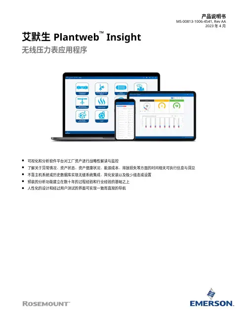
产品说明书MS-00813-1006-4541, Rev AA2023 年 4 月艾默生 Plantweb™ Insight无线压力表应用程序■可视化和分析软件平台对工厂资产进行战略性解读与监控■了解关于异常情况、资产状态、资产健康状况、能源成本、排放损失等方面的时间相关可执行信息与洞见■不靠主机系统或历史数据库实现无缝系统集成、简化安装以及极少组态或设置■预装的分析功能建立在数十年的过程经验和行业经验的基础之上■人性化的设计和经过用户测试的界面可实现一致而直观的导航功能和优点实时了解异常情况■资产监测应用程序套装,可利用数据分析和模型识别异常情况和故障。
■通过提醒和故障识别功能,在影响经济收益之前了解问题。
■直观且易于读取的视图突出显示高优先级的可执行信息。
安全可靠的轻量级软件包便于无缝集成到当前的基础架构■通过虚拟机轻松部署。
■随时从多种 Web 浏览器访问界面。
■人性化的设计便于快速、直观地启动和组态。
■与现有无线生态系统集成,以扩展功能并利用现有资产。
■不依靠 DCS、主机系统或历史数据库。
内容功能和优点 (2)用户界面 (4)无线压力表应用程序 (5)通讯规格 (6)订购信息 (7)技术规格 (9)艾默生 Plantweb Insight 2023 年 4 月/Rosemount2023 年 4 月艾默生 Plantweb Insight 通过完全可扩展的软件包和众多应用程序监测一种或数千种资产■应用程序基于关键资产,例如疏水器、泵、热交换器、泄压阀以及其他资产。
■从小处着手,或从单点监测所有资产。
■与其他商业系统(例如数据历史数据库)集成。
■可以部署在小型、大型或企业级运营中。
艾默生 Plantweb Insight 3用户界面PlantwebInsight 套件中的所有应用程序都采用相似的外观和风格,使用户获得一致的体验。
主要视图可分成三层。
仪表板仪表板页面是所监测资产类别的整体概览。
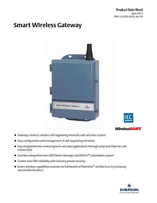
Product Data SheetApril 201300813-0200-4420, Rev FA⏹Gateway connects wireless self-organizing networks with any host system ⏹Easy configuration and management of self-organizing networks⏹Easy integration into control systems and data applications through serial and Ethernet LAN connections⏹Seamless integration into AMS Device Manager and DeltaV™ automation system ⏹Greater than 99% reliability with industry proven security⏹Smart Wireless capabilities extends the full benefit of PlantWeb ® architecture to previously inaccessible locationsSmart Wireless GatewaySmart Wireless Gateway April 2013Emerson Smart Wireless GatewayGain real-time process information with greater than 99% wireless data reliability⏹The Smart Wireless Gateway automatically manages wireless communications in constantly changing environments⏹Native integration with DeltaV and Ovation automation systems provides simple and fast commissioning for wireless field networks⏹Connect to data historians, legacy host systems, and other via a LAN applications through Ethernet, Modbus, Serial, OPC, EtherNet/IP, and HART outputsGuarantee system availability withredundant Smart Wireless Gateways⏹Never lose the wireless network with hot standby capabilityand automatic fault detection⏹Smart Wireless Gateways function as a single system,eliminating the need for duplicate host integration⏹One click configuration and plug-and-play architectureComplete wireless network configuration toolsprovided with each Gateway⏹The integrated web interface allows easy configuration of thewireless network and data integration without the need to installadditional software⏹Complimentary AMS Wireless Configurator software providesEmerson Device Dashboards to configure devices and viewdiagnostic dataDrag and Drop device provisioning enables asecure method to add new wireless devices tothe wireless field networkContentsEmerson’s Smart Wireless Solution .. . . . . . . . . page3IEC 62591 (WirelessHART®)... The Industry Standard page3Ordering Information . . . . . . . . . . . . . . . . . . . . . page4Accessories and Spare parts . . . . . . . . . . . . . . . . page5 Specifications . . . . . . . . . . . . . . . . . . . . . . . . . . . . page6 Product certifications . . . . . . . . . . . . . . . . . . . . . page8 Dimensional drawings . . . . . . . . . . . . . . . . . . . . . page9Smart Wireless Gateway April 2013Emerson’s Smart Wireless SolutionIEC 62591 (Wireless HART®)... The Industry StandardSelf-Organizing, Adaptive Mesh Routing⏹No wireless expertise required, network automatically finds the best communication paths⏹The self-organizing, self-healing network manages multiple communication paths for any given device. If an obstruction is introduced into the network, data will continue to flow because the device already has other established paths. The network will then lay in more communication paths as needed for that device.Reliable Wireless Architecture⏹Standard IEEE 802.15.4 radios⏹2.4 GHz ISM band sliced into 15 radio-channels⏹Time Synchronized Channel Hopping to avoid interference from other radios, WiFi, and EMC sources and increase reliability⏹Direct sequence spread spectrum (DSSS) technology delivers high reliability in challenging radio environment Emerson’s Smart WirelessSeamless Integration via a LAN to All Existing Host Systems ⏹Native integration into DeltaV and Ovation is transparent and seamless⏹Gateways interface with existing host systems via a LAN, using industry standard protocols including OPC, Modbus TCP/IP, Modbus RTU, and EtherNet/IPLayered Security Keeps Your Network Safe⏹Ensures that data transmissions are received only by the Smart Wireless Gateway⏹Network devices implement industry standard Encryption, Authentication, Verification, Anti-Jamming, and Key Management⏹Third party security verification including Achilles andFIPS197- User based login and enforced password strength. Password strength monitoring, user based log in, password reset requirements, automatic lockout, password expiration requirements. Based on guidelines from ISA99.03.03 standard approved level two. SmartPower™ Solutions⏹Optimized Emerson instrumentation, both hardware and software, to extend power module life⏹SmartPower technologies enable predictable power lifeSmart Wireless Gateway April 2013 Ordering InformationTable 1. Smart Wireless Gateway Ordering Information★ The Standard offering represents the most common options. The starred options (★) should be selected for best delivery.The Expanded offering is subject to additional delivery lead time.Model Product Description1420Smart Wireless GatewayPower InputStandard StandardA24 VDC Nominal (10.5-30 VDC)★Ethernet Communications - Physical ConnectionStandard Standard1(1)(2)Ethernet★2(3)(4)Dual Ethernet★Wireless Update Rate, Operating Frequency, and ProtocolStandard StandardA3User Configurable Update Rate, 2.4 GHz DSSS, Wireless HART★Serial Communication]Standard StandardN None★A(5)Modbus RTU via RS485★Ethernet Communication - Data ProtocolsStandard Standard2Webserver, Modbus TCP/IP, AMS Ready, HART-IP★4Webserver, Modbus TCP/IP, AMS Ready, HART-IP, OPC★5(6)DeltaV Ready★6(6)Ovation Ready ★8Webserver, EtherNet/IP, AMS Ready, HART-IP★9Webserver, EtherNet/IP, Modbus TCP/IP, AMS Ready, HART-IP★Options (Include with selected model number)Product CertificationsStandard StandardN5FM Division 2, Non-incendive★N6CSA Division 2, Non-incendive★N1ATEX Type n★ND ATEX Dust★N7IECEx Type n★NF IECEx Dust★KD FM & CSA Division 2, Non-incendive and ATEX Type n★N3China Type n★N4TIIS Type n★Redundancy OptionsStandard Standard RD(7)(8)(9)Gateway Redundancy★AdaptersStandard StandardJ1CM 20 Conduit Adapters★J2PG 13.5 Conduit Adapters★J33/4 NPT Conduit Adapters★Antenna Options(10)Standard Standard WL2Remote Antenna Kit, 50 ft. (15.2 m) cable, Lightning Arrestor★Smart Wireless GatewayApril 2013Accessories and Spare partsWL3Remote Antenna Kit, 20 ft. (6.1 m) and 30 ft. (9.1 m) cables, Lightning Arrestor ★WL4Remote Antenna Kit, 10 ft. (3.0 m) and 40 ft. (12.2 m) cables, Lightning Arrestor ★Expanded WN2(11)High-Gain, Remote Antenna Kit, 25 ft. (7.6m) cable, Lightning ArrestorTypical Model Number:1420A2A3 A 2 N5(1)Single active 10/100 baseT Ethernet port with RJ45 connector.(2)Additional ports disabled.(3)Dual active 10/100 baseT Ethernet ports with RJ45 connectors.(4)Multiple active ports have separate IP addresses, firewall isolation, and no packet forwarding.(5)Convertible to RS232 via adaptor, not included with Gateway.(6)Includes Webserver, Modbus TCP, AMS Ready, HART-IP, and OPC.(7)Requires the selection of Dual Ethernet option code 2.(8)Not available with DeltaV Ready option code 5.(9)Not available with EtherNet/IP option codes 8 and 9(10)The WL2, WL3, WL4, and WN2 options require minor assembly.(11)Not available in all countriesTable 1. Smart Wireless Gateway Ordering Information★ The Standard offering represents the most common options. The starred options (★) should be selected for best delivery.The Expanded offering is subject to additional delivery lead time. Table 2. AccessoriesItem DescriptionPart Number AMS® Wireless SNAP-ON™, 1 Gateway License 01420-1644-0001AMS Wireless SNAP-ON, 5 Gateway Licenses 01420-1644-0002AMS Wireless SNAP-ON, 10 Gateway Licenses 01420-1644-0003AMS Wireless SNAP-ON, 5-10 Upgrade Licenses 01420-1644-0004Serial Port HART Modem and Cables only 03095-5105-0001USB Port HART Modem and Cables only03095-5105-0002Table 3. Spare PartsItem DescriptionPart Number Spare Kit, WL2 Replacement (1), Remote Antenna, 50 ft. (15.2 m) Cable, and Lightning Arrestor01420-1615-0302Spare Kit, WL3 Replacement (1), Remote Antenna, 20/30 ft. (6.1/9.1 m) Cables, and Lightning Arrestor01420-1615-0303Spare Kit, WL4 Replacement (1), Remote Antenna, 10/40 ft. (3.0/12.2 m) Cables, and Lightning Arrestor 01420-1615-0304Spare Kit, WN2 Replacement (1), High Gain, Remote Antenna, 25 ft. (7.6 m) Cable, and Lightning Arrestor (2)01420-1615-0402(1)Can not upgrade from integral to remote antenna.(2)Not available in all countries.Smart Wireless GatewayApril 2013SpecificationsFunctional SpecificationsInput Power10.5 - 30 VDCCurrent DrawRadio Frequency Power Output from AntennaMaximum of 10 mW (10 dBm) EIRPMaximum of 40 mW (16 dBm) EIRP for WN2 High Gain optionEnvironmentalOperating Temperature Range: -40 to 158 °F (-40 to 70 °C)Operating Humidity Range: 10-90% relative humidityEMC PerformanceComplies with EN61326-1:2006.Antenna OptionsIntegrated Omnidirectional AntennaOptional remote mount Omnidirectional AntennaPhysical SpecificationsWeight10 lb (4.54 kg)Material of ConstructionHousingLow-copper aluminum, NEMA 4X PaintPolyurethaneCover GasketSilicone Rubber AntennaIntegrated Antenna: PBT/PC Remote Antenna: Fiber Glass CertificationsClass I Division 2 (U.S.)Equivalent WorldwideCommunication SpecificationsIsolated RS4852-wire communication link for Modbus RTU multidrop connectionsBaud rate: 57600, 38400, 19200, or 9600Protocol: Modbus RTUWiring: Single twisted shielded pair, 18 AWG. Wiring distance up to 4,000 ft. (1,524 m)Ethernet10/100base-TX Ethernet communication portProtocols: EtherNet/IP Modbus TCP, OPC, HART-IP, HTTPS (for Web Interface)Wiring: Cat5E shielded cable. Wiring distance 328 ft. (100 m).ModbusSupports Modbus RTU and Modbus TCP with 32-bit floating point values, integers, and scaled integers.Modbus Registers are user-specified.OPCOPC server supports OPC DA v2, v3EtherNet/IPSupports EtherNet/IP protocol with 32 bit Floating Point values and Integers.EtherNet/IP Assembly Input-Output instances are user configurable.EtherNet/IP specifications are managed and distributed by ODVA.Self-Organizing Network SpecificationsProtocolIEC 62591 (Wireless HART), 2.4 - 2.5 GHz DSSS.Maximum Network Size100 wireless devices @ 8 sec or higher.50 wireless devices @ 4 sec.25 wireless devices @ 2 sec.12 wireless devices @ 1 sec.Supported Device Update Rates1, 2, 4, 8, 16, 32 seconds or 1 - 60 minutesNetwork Size/Latency100 Devices: less than 10 sec.50 Devices: less than 5 sec.Data Reliability>99%C u r r e n t (m A )Operating Current Draw is based on 3.6 Watts average powerconsumption. Momentary startup Current Draw up to twice Operating Current Draw.Smart Wireless Gateway April 2013System Security SpecificationsEthernetSecure Sockets Layer (SSL)- enabled (default) TCP/IPcommunicationsSmart Wireless Gateway AccessRole-based Access Control (RBAC) including Administrator,Maintenance, Operator, and Executive. Administrator hascomplete control of the gateway and connections to hostsystems and the self-organizing network.Self-Organizing NetworkAES-128 Encrypted Wireless HART, including individual sessionkeys. Drag and Drop device provisioning, including unique joinkeys and white listing.Internal FirewallUser Configurable TCP ports for communications protocols,including Enable/Disable and user specified port numbers.Inspects both incoming and outgoing packets.Third Party CertificationWurldtech: Achilles Level 1 certified for network resiliency.National Institute of Standards and Technology (NIST):Advanced Encryption Standard (AES) Algorithm conforming toFederal Information Processing Standard Publication 197(FIPS-197)Smart Wireless Gateway April 2013 Product certificationsApproved Manufacturing LocationsRosemount Inc. – Chanhassen, Minnesota, USAEmerson Process Management GmbH & Co. - Karlstein, GermanyEmerson Process Management Asia Pacific Private Limited - SingaporeBeijing Rosemount Far East Instrument Co., Limited - Beijing, ChinaTelecommunication ComplianceAll wireless devices require certification to ensure that they adhere to regulations regarding the use of the RF spectrum. Nearly every country requires this type of product certification. Emerson is working with governmental agencies around the world to supply fully compliant products and remove the risk of violating country directives or laws governing wireless device usage.FCC and ICThis device complies with Part 15 of the FCC Rules. Operation is subject to the following conditions. This device may not cause harmful interference. This device must accept any interference received, including interference that may cause undesired operation. This device must be installed to ensure a minimum antenna separation distance of 20 cm from all persons. Ordinary Location Certification for FMAs standard, the Gateway has been examined and tested to determine that the design meets basic electrical, mechanical, and fire protection requirements by FM, a nationally recognized testing laboratory (NRTL) as accredited by the Federal Occupational Safety and Health Administration (OSHA).North American CertificationsN5FM Division 2, Non-IncendiveCertificate Number: 3028321Nonincendive for Class I, Division 2, Groups A, B, C, and D.Suitable for Class II, III, Division 1,Groups E, F, and G; Indoors/outdoor locations;Type 4XTemperature Code: T4 (-40 °C < T a < 60 °C)Canadian Standards Association (CSA)N6CSA Division 2, Non-IncendiveCertificate Number: 1849337Suitable for Class I, Division 2, Groups A, B, C, and D.Dust Ignition-proof for Class II, Groups E, F, and G;Suitable for Class III Hazardous Locations.;Install per Rosemount drawing 01420-1011.Temperature Code: T4 (-40 °C < T a < 60 °C)CSA Enclosure Type 4X European Union Directive InformationThe EC declaration of conformity for all applicable European directives for this product can be found on the Rosemount websiteat . A hard copy may be obtained by contacting your local sales representative.European CertificationN1ATEX Type nEx nA nL IIC T4 (-40 °C < T a< 60 °C)Special condition for safe use (X):The surface resistivity of the antenna is greater than onegigaohm. To avoid electrostatic charge build-up, it mustnot be rubbed or cleaned with solvents or a dry cloth.The Apparatus is not capable of withstanding the 500Vinsulation test required by Clause 9.4 of EN 60079-15:2005. This must be taken into account when installing the apparatus.ND ATEX DustCertificate Number: Baseefa 07ATEX0057Ex tD A 22 IP66 T135 (-40 °C < T a < 60 °C)Maximum working Voltage = 28 VN7IECEx Type nCertificate Number: IECEx BAS 07.0012XEx nA nL IIC T4 (-40 °C < T a < 60 °C)Maximum working voltage = 28 VSpecial condition for safe use (X):The surface resistivity of the antenna is greater than onegigaohm. To avoid electrostatic charge build-up, it mustnot be rubbed or cleaned with solvents or a dry cloth.The Apparatus is not capable of withstanding the 500 Vinsulation test required by Clause 9.4 of EN 60079-15:2005. This must be taken into account when installing the apparatus.NF IECEx DustCertification Number: IECEx BAS 07.0013Ex tD A22 IP66 T135 (-40 °C < T a < 60 °C)Maximum working voltage = 28 VCombinations of CertificationsKD Combination of N5, N6, and N1.Smart Wireless Gateway April 2013Dimensional drawingsFigure 1. Smart Wireless Gateway Dimensions are in inches (millimeters)Smart Wireless Gateway April 2013 Remote Antenna KitThe Remote Antenna kit includes sealant tape for remote antenna connection, as well as mounting brackets for the antenna, Lightning Arrestor, and the Smart Wireless Gateway.Lightning protection is included on all the options.*Note that the cables lengths on the remote antenna options WL3 and WL4 are interchangeable for installation convenience.Smart Wireless Gateway April 201311Standard Terms and Conditions of Sale can be found at \terms_of_sale The Emerson logo is a trade mark and service mark of Emerson Electric Co.Rosemount and the Rosemount logotype are registered trademarks of Rosemount Inc.PlantWeb is a registered trademark of one of the Emerson Process Management group of companies.HART and WirelessHART are registered trademarks of the HART Communication Foundation Modbus is a trademark of Modicon, Inc.All other marks are the property of their respective owners.© 2012 Rosemount Inc. All rights reserved.Emerson Process Management Rosemount Inc.8200 Market Boulevard Chanhassen, MN 55317 USA T (U.S.) 1-800-999-9307T (International) (952) 906-8888F (952) Emerson Process Management Blegistrasse 23P.O. Box 1046CH 6341 Baar Switzerland T +41 (0) 41 768 6111F +41 (0) 41 768 Emerson Process Management Asia Pacific Pte Ltd 1 Pandan Crescent Signapore 128461T +65 6777 8211F +65 6777 0947Service Support Hotline: +65 6770 8711Email:***************************.comSmart Wireless Gateway00813-0200-4420, Rev FAProduct Data Sheet April 2013Emerson Process Management Latin America 1300 Concord Terrace, Suite 400Sunrise Florida 33323 USA Tel + 1 954 846 5030。
AMSamotion帮助一百万家企业实现自动化智能制造WiFi无线PLC编程器使用手册(对应艾莫迅串口转TCP工具v6.0版本)[第一版]艾莫迅自动化科技(东莞)有限公司目录第一章WiFi电缆使用情景 (1)1-1.现场版WiFi电缆 (2)1-2.远程版WiFi电缆 (2)1-2-1.远程模式 (2)1-2-2.现场版AP模式 (3)1-2-3.现场版ST模式 (3)第二章艾莫迅串口转TCP工具应用 (4)2-1.软件的安装 (4)2-2.软件使用说明 (6)第三章指示灯及按键说明 (9)3-1.指示灯说明 (9)3-2.按键说明 (9)第四章WiFi电缆通讯步骤 (10)4-1.现场版WiFi电缆通讯 (10)4-2.远程版WiFi电缆通讯 (11)4-2-1.远程模式 (11)4-2-2.现场版AP模式 (15)4-2-3.现场版ST模式 (15)第五章通讯问题分析 (17)5-1.通用情况分析 (17)5-2.按通讯模式分析 (18)第六章应用拓展 (19)6-1.MODBUS开关量模块的无线控制 (19)6-2.组态王与PLC连接 (22)6-3.连接扩展 (24)6-4.定制开发 (24)附录 (25)第一章WiFi电缆使用情景通过WiFi电缆可对PLC/触摸屏等控制设备,以无线的方式现场短距离(空旷处理论30m)或远程,进行程序的上下载及监控,按不同功能分不同使用情景。
1-1.现场版WiFi电缆该电缆Model名称不带“-R”,WiFi名称数字部分不以0开头,上电PWR红灯常亮,仅此一种通讯模式,应用在现场范围30m内(理论值,受环境或干扰等因素可能降低)的电脑编程软件与PLC的通讯,电脑连接电缆的WiFi后无法上网1-2.远程版WiFi电缆Model名称带“-R”,WiFi名称数字部分以0开头,含有3种通讯模式:远程模式、现场版AP模式、现场版ST模式1-2-1.远程模式该模式为出厂通讯模式,当WiFi电缆和装有上位机的电脑均连外网时,即可在异地进行远程控制PLC。

P/N: 1802034700012 *1802034700012*OnCell G3470A-LTE Series Quick Installation GuideMoxa OnCell SeriesVersion 2.2, January 2021Technical Support Contact Information/support2021 Moxa Inc. All rights reserved.OverviewThe OnCell G3470A-LTE is Moxa's 4G/Ethernet IP gateway that provides a higher cellular bandwidth and more reliable connection to your Ethernet network for cellular applications. With the integrated 4-port gigabit Ethernet switch and 4G LTE support, the OnCell G3470A-LTE offers a faster cellular connection with a lower total cost of ownership. To enhance reliability, a key for industrial users, the OnCell G3470A-LTE features isolation design for both power and antenna inputs. Coupled withhigh-level EMS and wide-temperature support, the OnCell G3470A-LTE provides the highest level of device stability in any rugged environment. In addition, with dual SIM and dual power-input features, the OnCellG3470A-LTE supports network redundancy to ensure an uninterrupted connectivity in your applications.Package ChecklistMoxa’s OnCell G3470A-LTE is shipped with the following items. If any of these items is missing or damaged, please contact your customer service representative for assistance.•OnCell G3470A-LTE• 1 GPS connector terminator• 2 2G/3G/4G omni-directional antennas, 2 dBi, SMA (male)• 5 plastic RJ45 protective caps for serial console and Ethernet ports •Quick installation guide (printed)•Warranty cardInstallation and ConfigurationBefore installing the OnCell G3470A-LTE, make sure that all items in the package checklist are in the box. In addition, you will need access to a notebook computer or PC equipped with an Ethernet port. The OnCellG3470A-LTE has a default IP address that you must use when connecting to the device for the first time.Step 1: Insert a SIM card and turn on the OnCell G3470A-LTE Insert one or two 2G/3G/4G SIM cards into the SIM slots located on the bottom of the OnCell G3470A-LTE. Then, turn on the OnCell G3470A-LTE by connecting a power terminal block to a DC power source (12 to 48 VDC).Step 2: Connect the OnCell G3470A-LTE to a notebook or PC Since the OnCell G3470A-LTE supports MDI/MDI-X auto-sensing, you can use either a straight-through cable or crossover cable to connect the OnCell G3470A-LTE to a computer. If the LED indicator on the OnCellG3470A-LTE’s LAN port lights up, it means a connection has been established.Step 3: Set up the computer’s IP addressSet an IP address on the same subnet as the OnCell G3470A-LTE. Since the OnCell G3470A-LTE’s default IP address is 192.168.127.254, and the subnet mask is 255.255.255.0, you should set the IP address of the computer to 192.168.127.xxx and subnet mask to 255.255.255.0.Step 4: Use the web-based manager to configure the OnCellG3470A-LTEOpen your computer’s web browser and type http://192.168.127.254 in the address field to access the homepage of the web-based management system. Before the homepage opens, you will need to enter the user name and password. For first-time configuration, enter the default user name and password and then click on the Login button: User name: adminPassword: moxaNOTE For the change to take effect, you must click Save Configuration to save the change, or Restart (clicking the Save and Restartbuttons will save all changes).Hardware Overview1. GPS antenna connector (femaleSMA)2. Terminal block (two digital inputand one digital relay) 3. Grounding screw (M5)4. Terminal block (PWR1 andPWR2)5. 2x2 MIMO antenna ports for LTE(female SMA)6. RS-232 serial console (RJ45)7. 10/100/1000 BaseT(X) Ethernetports (RJ45) 8. LED display9. DIN-rail mounting kit 10. Reset button11. Dual SIM – SIM1 12.Dual SIM – SIM2Device DimensionsDIN-Rail MountingDIN-Rail Kit Dimensions:Unit = mm (inch)The DIN-rail kit is attached to the back panel of the OnCell G3470A-LTE series. Mount the OnCell G3470A-LTE series on corrosion-free mounting rails that meet the EN 60715 standard.InstallationSTEP 1: Insert the upper lip ofthe DIN rail into the DIN-railmounting kit.STEP 2: Press the OnCellG3470A-LTE series towards theDIN rail until it snaps into place.RemovalSTEP 1: Pull down the latch onthe mounting kit using ascrewdriver.STEP 2: Slightly pull the OnCellG3470A-LTE forward.STEP 3: Lift up to remove theOnCell G3470A-LTE from theDIN railWall Mounting (optional)Wall-mount Kit Dimensions:Unit = mm (inch)For some applications, it may be more convenient to mount the OnCell G3470A-LTE to a wall, as illustrated below. STEP 1:Remove the aluminum DIN-rail attachment plate from the OnCellG3470A-LTE, and then attach the wall mount plates with M3 screws, as shown in the adjacent diagram.STEP 2:Mounting the OnCell G3470A-LTE to a wall requires 4 screws. Use the OnCell G3470A-LTE device, with wall mount plates attached as a guide, to mark the correct locations of the 4 screws. The heads of the screws should be less than 6.0 mm in diameter, and the shafts should be less than 3.5 mm in diameter, as shown in the figure at the right.NOTE Test the screw head and shank size by inserting the screw into one of the keyhole shaped apertures of the Wall Mounting Plates before it is screwed into the wall.STEP 3:Once the screws are fixed into the wall, insert the four screw heads through the large opening of the keyhole-shaped apertures, and then slide the OnCell G3470A-LTE downwards, as indicated in the accompanying diagram. Tighten the four screws for added stability.Wiring RequirementsYou should also pay attention to the following items:•Use separate paths to route wiring for power and devices. If power wiring and device wiring paths must cross, make sure the wires are perpendicular at the intersection point.NOTE: Do not run signal or communications wiring and power wiring in the same wire conduit. To avoid interference, wires with different signal characteristics should be routed separately.•You can use the type of signal transmitted through a wire to determine which wires should be kept separate. The rule of thumb is that wiring with similar electrical characteristics can be bundledtogether.•Keep input wiring and output wiring separate.•It is strongly advised that you label wiring to all devices in the system when necessary.Grounding the Moxa OnCell G3470A-LTEGrounding and wire routing help limit the effects of noise due to electromagnetic interference (EMI). Run the ground connection from the ground screw to the grounding surface prior to connecting devices.Wiring the Redundant Power InputsThe top two pairs of contacts of the 10-contact terminal block connector on the OnCell G3470A-LTE’s top panel are used for the OnCellG3470A-LTE’s two DC inputs. Top and front views of the terminal block connector are shown here.STEP 1: Insert the negative/positive DC wires Array into the V-/V+ terminals.STEP 2: To keep the DC wires from pulling loose,use a small flat-blade screwdriver to tighten thewire-clamp screws on the front of the terminalblock connector.STEP 3: Insert the plastic terminal blockconnector prongs into the terminal blockreceptor, which is located on the OnCellG3470A-LTE’s top panel.Wiring the Relay ContactThe OnCell G3470A-LTE has one relay output, which consists of the two contacts of the terminal block on the OnCell G3470A-LTE’s top panel. Refer to the Specification section for detailed electrical requirement. The relay contacts are used to indicate user-configured events. The two wires attached to the relay contacts form an open circuit when auser-configured event is triggered. If a user-configured event does not occur, the relay circuit will be closed.Wiring the Digital InputsThe OnCell G3470A-LTE has two sets of digital inputs—DI1 and DI2. Each DI comprises two contacts of the 6-pin terminal block connector on the OnCell G3470A-LTE’s top panel. Refer to the Specification section for detailed information on isolated digital input definition.Communication Connections10/100BaseT(X) Ethernet Port ConnectionThe 10/100BaseT(X) ports located on the OnCell G3470A-LTE’s front panel are used to connect to Ethernet-enabled devices.Below we show pinouts for both MDI (NIC-type) ports and MDI-X (HUB/Switch-type) ports. MDI Port Pinouts MDI-X Port Pinouts8-pin RJ45Pin Signal 1 Tx+ 2 Tx- 3 Rx+ 6Rx- Pin Signal 1 Rx+ 2 Rx- 3 Tx+ 6Tx-1000BaseT Ethernet Port Connection1000BaseT data is transmitted on differential TRD+/- signal pairs over copper wires.MDI/MDI-X Port PinoutsPin Signal 1 TRD(0)+ 2 TRD(0)- 3 TRD(1)+ 4 TRD(2)+ 5 TRD(2)- 6 TRD(1)- 7 TRD(3)+ 8TRD(3)-RS-232 ConnectionThe OnCell G3470A-LTE has one RS-232 (8-pin RJ45) console portlocated on the front panel. Use either an RJ45-to-DB9 or RJ45-to-DB25 cable to connect the Moxa OnCell G3470A-LTE’s console port to your PC’s COM port. You may then use a console terminal program to access the OnCell G3470A-LTE for console configuration. Console Pinouts for 10-pin or 8-pin RJ45 10-PinDescription8-Pin 1 – 2 DSR 1 3 RTS 2 4 GND 3 5 TxD 4 6 RxD 5 7 DCD 6 8 CTS 7 9 DTR 8 10–NOTE The pin numbers for both 8-pin and 10-pin RJ45 connectors (and ports) are typically not labeled on the connector (or port). Referto the Pinout diagram above to see how RJ45 pins are numbered.LED IndicatorsThe front panel of the Moxa OnCell G3470A-LTE contains several LED indicators. The function of each LED is described in the table below. LED Color State DescriptionPWR1 Green On Power is being supplied from power input 1. PWR2 Green On Power is being supplied from power input 2.READY Green OnSystem startup is complete and the systemis operating.BlinkingDevice has been located by the OnCellSearch Utility.Off Power is off, or the system is booting up.FAULT Red OnSystem configuration error or a relay eventhas occurred.Blinking IP address conflict.Off Power is off, or there is no error condition.CELLULARSIGNAL (3 LEDs) Green OnNumber of LEDs to indicate cellular signallevel when registered to a base station.Signal LED 1: 0 < RSSI ≤ 12Signal LED 2: 12 < RSSI ≤ 20Signal LED 3: 20 < RSSI ≤ 31SIM1 Amber On/Off SIM 1 is active or inactive.Blinking SIM 1 is not inserted or PIN code is incorrect.SIM2 Amber On/Off SIM 2 is active or inactive.Blinking SIM 2 is not inserted or PIN code is incorrect.2G Amber On Registered to a base station with cellular connection in GPRS or EDGE mode.3G Amber On Registered to a base station with cellular connection in UMTS or HSPA mode.4G Amber On Registered to a base station with cellular connection in LTE mode.GPS Green On GPS has been located.BlinkingLocating GPS or less than four satellites havebeen located.Off GPS has not been located.1000M Green On 1000Mbps link is active.Blinking Data is being transmitted at 1000Mbps. Off 1000Mbps link is inactive.10/100M Amber On 10/100Mbps link is active.Blinking Data is being transmitted at 10/100Mbps. Off 10/100Mbps link is inactive.SpecificationsCellular SpecificationStandards GSM/GPRS/EDGE/UMTS/HSPA/LTEBand Options OnCell G3470A-LTE-EU: B1 (2100 MHz)/B3 (1800MHz)/B7 (2600 MHz)/B8 (900 MHz)/B20 (800 MHz)OnCell G3470A-LTE-US: B2 (1900 MHz)/B4(AWS)/B5 (850 MHz)/B13 (700 MHz)/B17 (700MHz)/B25 (1900 MHz)OnCell G3470A-LTE-EU: UMTS/HSPA2100/1900/850/800/900 MHzOnCell G3470A-LTE-US: UMTS/HSPA2100/1900/AWS/850/900 MHzQuad-band GSM/GPRS/EDGE 850/900/1800/1900MHzLTE Data Rate Category 3Downlink: 100 Mbps (20 MHz bandwidth), 50 Mbps(10 MHz bandwidth)Uplink: 50 Mbps (20 MHz bandwidth), 25 Mbps (10MHz bandwidth)HSPA Data Rate Downlink: Up to 42 Mbps (category 24)Uplink: Up to 5.76 Mbps (category 6)GPRS Data Rate Downlink/Uplink: 236 kbpsInterfaceCellular Antenna Connectors 2 SMA (female), MIMO for LTE, antenna diversity for WCDMASIM Slots Dual SIM card supportGNSS 1 SMA (female), GPS: 1575.42 MHz, GLONASS:1602 MHzEthernet 4, 10/100/1000 Mbps auto negotiation speed, F/Hduplex mode and auto MDI/MDI-X connection(RJ45-type)Serial Console Port 1, RS-232 (RJ45-type)LED Indicators PWR1, PWR2, READY, FAULT, CELLULAR SIGNAL,SIM1, SIM2, 2G, 3G, 4G, GPSAlarm Contact 1 relay output with current carrying capacity of 1 A@ 24 VDCDigital Inputs 2 electrically isolated inputs+13 to +30 V for state “1”+3 to -30 V for state “0”Max. input current: 8 mAGround Screw M5Reset Button Power Reset/Factory Default ResetSoftware SpecificationNetwork Protocol ICMP, TCP/IP, UDP, DHCP, Telnet, DNS, SNMP,HTTP, HTTPS, SMTP, SNTP, ARPRouting/Firewall NAT, Port Forwarding, IP/MAC/Port FilteringVPN Max. Tunnel Number: 5 (Responder/Initiator)IPSec (DES, 3DES, AES, MD5, SHA-1, DH2, DH5),PSK/X.509/RSAManagement Options Remote SMS Control, SNMPv1/v2c/v3, Web/Telnet/Serial ConsoleOthers DDNSSoftware Specification (Moxa Proprietary)GuaranLink 3-tier heart-beat for reliable and persistent cellularconnectivityOnCell Central Management Large scale centralized device management over private cellular IP addressesSearch Utility Simple device configuration and managementutilityPhysical CharacteristicsHousing Metal casing for high EMC-level, providing IP30protectionMounting DIN-rail (default) or wall-mount (optional) Weight 1300 gDimension 67 x 90.5 x 124 mm (2.6 x 3.52 x 4.83 inch) Installation DIN-Rail mounting, wall mounting (with optionalkit)Environmental LimitsOperating Temperature Standard Models: -30 to 55°C (-22 to 131°F) Wide Temp. Models: -30 to 70°C (-22 to 158°F) Storage Temperature-40 to 75°C (-40 to 167°F)Ambient Relative Humidity5 to 95% (30°C, non-condensing)Power RequirementsInput Voltage 12 to 48 VDC, redundant dual DC power inputs Connector 4-pin removeable terminal blockPower Consumption 9.6 W (12 V/0.78 A to 48 V/0.2 A)Reverse Polarity ProtectionPresentStandards and CertificationsSafety OnCell G3470A-LTE-US: UL 60950-1EMI OnCell G3470A-LTE-US: FCC Part 15 Subpart B EMS OnCell G3470A-LTE-EU: EN 61000-6-2/-4 Radio OnCell G3470A-LTE-US: FCC ID N7NMC7355OnCell G3470A-LTE-EU: EN 301 489-1, EN 301489-7, EN 301 511/4ReliabilityMTBF 327326 hoursWarrantyWarranty Period 5 yearsDetails See /support/warranty.aspx。


PowerMaster智能高频开关电力操作电源系统合作生产技术指导书资料版本归档日期2008-10-17BOM 编码艾默生网络能源有限公司为客户提供全方位的技术支持,用户可与就近的艾默生网络能源有限公司办事处或客户服务中心联系,也可直接与公司总部联系。
艾默生网络能源有限公司版权所有,保留一切权利。
内容如有改动,恕不另行通知。
艾默生网络能源有限公司地址:深圳市南山区科技工业园科发路一号邮编:518057公司网址:客户服务投诉热线:0E-mail第一章充电模块(必选件)1.1 HD22010-3系列1.1.1 模块简介HD22010-3系列充电模块是电力电源最主要的配置模块,广泛应用于35kV到330kV的变电站电力电源中。
HD22010-3系列充电模块采用自冷和风冷相结合的散热方式,在轻载时自冷运行,符合电力系统的实际运行情况。
型号说明产品系列产品系列见下表。
表1-1 订货信息工作原理概述以HD22010-3模块的工作原理框图如下图所示。
图1-1 HD22010-3充电模块原理图HD22010-3充电模块由三相无源PFC和DC/DC两个功率部分组成。
在两功率部分之外还有辅助电源以及输入输出检测保护电路。
前级三相无源PFC电路由输入EMI和三相无源PFC组成,用以实现交流输入的整流滤波和输入电流的校正,使输入电路的功率因素大于,以满足DL/T781-2001中三相谐波标准和GB/T 中相关EMI、EMC标准。
后级的DC/DC变换器由PWM发生器控制前级PFC输出的DC电压、经过高频变压器输出后再整流滤波输出DC电压等电路组成,用以实现将前级整流电压转换成电力操作系统要求的稳定的直流电压输出。
辅助电源在输入三相无源PFC之后,DC/DC变换器之前,利用三相无源PFC的直流输出,产生控制电路所需的各路电源。
输入检测电路实现输入过欠压、缺相等检测。
DC/DC的检测保护电路包括输出电压电流的检测,散热器温度的检测等,所有这些信号用以DC/DC的控制和保护。
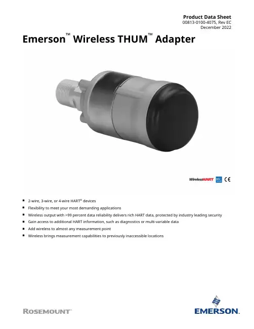
Product Data Sheet00813-0100-4075, Rev ECDecember 2022 Emerson™ Wireless THUM™ Adapter■2-wire, 3-wire, or 4-wire HART® devices■Flexibility to meet your most demanding applications■Wireless output with >99 percent data reliability delivers rich HART data, protected by industry leading security■Gain access to additional HART information, such as diagnostics or multi-variable data■Add wireless to almost any measurement point■Wireless brings measurement capabilities to previously inaccessible locationsIEC 62591(Wireless HART®)...the industry standardSelf-organizing, adaptive mesh routing■No wireless expertise required. Devices automatically find the best communication paths.■Network continuously monitors paths for degradation and repairs itself.■Adaptive behavior provides reliable, hands-off operation and simplifies network deployments, expansion, and reconfiguration.■Supports both star and mesh topologies. Industry standard radio with channel hopping■Standard IEEE 802.15.4 radios■ 2.4 GHz ISM band sliced into 16 radio channels■Continually “hop” across channels to avoid interference and increase reliability■Direct sequence spread spectrum (DSSS) technology delivers high reliability in challenging radio environmentSelf-healing network■The self-organizing, self-healing network manages multiple communication paths for any given device. If an obstruction is introduced into the network, data will continue to flow because the device already has other established paths. The network will then lay in more communication paths as needed for that device. Seamless integration to existing hosts■Transparent and seamless integration■Same control system applications■Gateways connect using industry protocolsContentsIEC 62591(Wireless HART®)...the industry standard. (2)Wireless THUM Adapter (3)Ordering Information (4)Specifications (7)Product Certifications (10)Dimensional Drawings (15)THUM Adapter December 2022Wireless THUM AdapterDevice specifications■Approvals: FM, CSA, ATEX, IECEx■Input: Either 2-wire, 3-wire, or 4-wire HART 5.0 device■SmartPower™: Power scavenging technology (no battery required)■Minimum load on loop 250 OhmsEnable enhanced valve capabilities■Online, in-service valve testing through AMS ValveLink SNAP-ON™Application.■Monitor alerts such as travel deviation with AMS Device Manager, supply pressure, and electronics health.■Trend actual valve position.Gain access to advanced instrument diagnostics■Rosemount™ 3051S with Advanced Process Diagnostics■Micro Motion™ Coriolis Meter Verification with optional AMS Meter Verification SNAP-ON■Rosemount Radar Echo Curve■Rosemount Magnetic Flow Meter Verification with AMS Device ManagerEfficiently gather data from multivariable devices■Rosemount 3051S MultiVariable™ Transmitter and Rosemount 3095 Mass Flow Transmitters■Rosemount 3300 and 5300 Radar Level Transmitters■Micro Motion Coriolis Meters■Rosemount TankRadar™ Rex and TankRadar Pro■Rosemount Magnetic Flow Meter■Rosemount MultiVariable Vortex Flow MeterMake any HART device wireless access new measurement information ■Level■Flow■Valves■Liquid and Gas Analytical■Pressure■TemperatureRemotely manage devices and monitor health with AMS Device Manager■Reduce troubleshooting time■As found, as left data■Calibration trackingDecember 2022THUM AdapterOrdering InformationOnline product configuratorMany products are configurable online using our Product Configurator. Select the Configure button or visit our website to start. With this tool's built-in logic and continuous validation, you can configure your products more quickly and accurately.Specifications and optionsSee the Specifications and options section for more details on each configuration. Specification and selection of product materials, options, or components must be made by the purchaser of the equipment. See the Material selection section for more information.Model codesModel codes contain the details related to each product. Exact model codes will vary; an example of a typical model code is shown in Figure 1.Figure 1: Model Code Example1.Required model components (choices available on most)2.Additional options (variety of features and functions that may be added to products)Optimizing lead timeThe starred offerings (★) represent the most common options and should be selected for the fastest delivery times.The nonstarred offerings are subject to additional delivery lead time.Required model components ModelRequires THUM Connection Box.THUM AdapterDecember 2022December 2022THUM Adapter OutputHousingMounting connectionPlantWeb functionalityCertificationTHUM Adapter December 2022Wireless update rate, operating frequency, and protocolOmni-directional antenna and SmartPower™ solutionsAccessoriesDecember 2022THUM Adapter SpecificationsFunctional specificationsInputAny 2-wire, 3-wire, or 4-wire HART powered deviceOutputIEC 62591 (Wireless HART®)Humidity limits0 - 100% relative humidityUpdate rateUser selectable, eight seconds to 60 minutesPhysical specificationsMaterial selectionEmerson provides a variety of Rosemount products with various product options and configurations, including materials of construction that can be expected to perform well in a wide range of applications. The Rosemount product information presented is intended as a guide for the purchaser to make an appropriate selection for the application. It is the purchaser’s sole responsibility to make a careful analysis of all process parameters (such as all chemical components, temperature, pressure, flow rate, abrasives, contaminants, etc.), when specifying product, materials, options, and components for the particular application. Emerson is not in a position to evaluate or guarantee the compatibility of the process fluid or other process parameters with the product, options, configuration, or materials of construction selected.Electrical connectionsThe THUM Adapter is connected into a powered 4–20 mA loop, powering itself by scavenging power. The THUM Adapter causes a voltage drop across the loop. The drop is linear from 2.25 V at 3.5 mA to 1.2 V at 25 mA, but does not effect the 4–20 mA signal on the loop. Under fault conditions, the maximum voltage drop is 2.5 V.Power supplyMinimum load on loop 250 OhmsTo maintain normal operating functions of the sub-device, the power in the loop must have at least a 2.5 V margin at a 250 Ω load.Limit the power supply to 0.5 A maximum.Limit the power supply to 30 Vdc maximum.Field Communicator connectionsUtilize wired device HART connectionsTHUM Adapter December 2022 Materials of constructionEnclosure■Housing option D: Low-copper aluminum■Housing option E: 316 SST■Paint: Polyurethane■M20 conduit adapter: SST■M20 conduit adapter O-ring: Buna-NAntennaPolybutadine terephthalate (PBT)/Polycarbonate (PC) integrated omni directional antennaWeight■THUM Adapter only AL: 0.65 lb (0.29 kg)■THUM Adapter only SST: 1.1 lb (0.5 kg)■AL THUM Adapter with AL remote kit: 3.2 lb (1.45 kg)■SST THUM Adapter with SST remote kit: 5.8 lb (2.65 kg)■AL THUM Adapter with M20 conduit adapter: 0.85 lb (0.038 kg)■SST THUM Adapter with M20 conduit adapter: 1.3 lb (0.59 kg)Enclosure ratingsHousing option code D and remote mount kits are enclosure Type 4X and IP66.MountingThe THUM Adapter may be attached directly to the conduit of any 2-wire or 4-wire HART device or mounted remotely by using remote mount kit.December 2022THUM Adapter Performance specificationsElectroMagnetic Compatibility (EMC)Meets all industrial environments of EN61326 and NAMUR NE-21 when installed with shielded wiring. The sub-device must also use shielded wiring for installation. Maximum deviation ≤1% span during EMC disturbance(1).Vibration effectOutput unaffected when tested per the requirements of IEC60770-1 field with general application or pipeline with low vibration level (10–60 Hz 0.15 mm displacement peak amplitude/60–500 Hz 2 g).When the THUM Adapter is used on wired devices that are subject to vibration levels greater than 2 g, it is recommended that the THUM Adapter be remotely mounted using the remote mount kit.Temperature limitsAmbient temperature-40 to 85 °C (-40 to 185 °F)Storage temperature-40 to 85 °C (-40 to 185 °F)(1)During the surge event, device may exceed maximum EMC deviation limit or reset; however, device will self-recover and return to normaloperation within specified start-up time.THUM Adapter December 2022 Product CertificationsRev 2.9European Directive InformationA copy of the EU Declaration of Conformity can be found at the end of the Quick Start Guide. The most recent revision of the EU Declaration of Conformity can be found at /Rosemount.Ordinary location certification from FM ApprovalsAs standard, the transmitter has been examined and tested to determine that the design meets the basic electrical, mechanical, and fire protection requirements by FM Approvals, a nationally recognized test laboratory (NRTL) as accredited by the Federal Occupational Safety and Health Administration (OSHA).Telecommunication compliance (for wireless products only)All wireless devices require certification to ensure that they adhere to regulations regarding the use of the RF spectrum. Nearly every country requires this type of product certification.Emerson is working with governmental agencies around the world to supply fully compliant products and remove the risk of violating country directives or laws governing wireless device usage.FCC and IC (for wireless products only)This device complies with Part 15 of the FCC Rules. Operation is subject to the following conditions: This device may not cause harmful interference. This device must accept any interference received, including interference that may cause undesired operation. This device must be installed to ensure a minimum antenna separation distance of 20 cm from all persons.Installing equipment in North AmericaThe US National Electrical Code® (NEC) and the Canadian Electrical Code (CEC) permit the use of Division marked equipment in Zones and Zone marked equipment in Divisions. The markings must be suitable for the area classification, gas, and temperature class. This information is clearly defined in the respective codes.USAE5 USA ExplosionproofCertificate CSA 2174201Standards FM Class 3600 - 2011, FM Class 3615 - 2006, ANSI/UL 61010-1 3rd EditionMarkings Class I, Division 1, Groups A, B, C and D; T5, T6; Type 4X and IP66 (–50 °C≤ T a≤ +70 °C)December 2022THUM Adapter I5 USA Intrinsically Safe (IS) and Non-incendiveCertificate3036224Standards FM Class 3600 - 1998, FM Class 3610 - 2007, FM Class 3611 - 2004, FM Class 3810 - 2005, NEMA 250 -2003, IEC 60529 - 2004Markings IS CL I, DIV 1, GP A, B, C, D; CL II, DIV 1, GP E, F, G; Class III; Class 1, Zone 0, AEx ia IIC T4; NI CL I, DIV 2, GP A, B, C, D T4; T4(–50 °C≤ T a≤ +70 °C) when connected per Rosemount drawing 00775-0010;Type 4X/IP66CanadaE6 Canada ExplosionproofCertificate CSA 2174201Standards CAN/CSA C22.2 No. 0-M91, CSA Std. C22.2 No. 30-M1986, CAN/CSA-C22.2 No. 94-M91, CAN/CSA-C22.2 No.61010-1-12, CSA Std. C22.2 No. 60529Markings Class I, Division 1, Groups A, B, C and D; T5, T6; Type 4X and IP66 (–50 °C≤ T a≤ +70 °C)I6 Canada Intrinsically SafeCertificate2174201Standards CAN/CSA C22.2 No. 0-M91 (R2001), CAN/CSA C22.2 No. 94-M91 (R2001), CSA Std C22.2 No. 142-M1987, CAN/CSA C22.2 No.157-92, CSA Std C22.2 No. 213-M1987, C22.2 No. 60529Markings Intrinsically Safe Class I, Division 1, Groups A, B, C, D T3C; Suitable for use in Class I, Division 2, Groups A, B, C, D T3C; T3C(–50 °C≤ T a≤ +70 °C) when installed per Rosemount drawing 00775-0012;Type 4X/IP66EuropeI1 ATEX Intrinsic SafetyCertificate Baseefa09ATEX0125XStandards IEC 60079-0:2011; EN60079-11:2012;Markings≤ T a≤ +70 °C)Special Conditions for Safe Use (X):1.The surface resistivity of the antenna is greater than 1GΩ. To avoid electrostatic charge build-up, it must not berubbed or cleaned with solvents or dry cloth.2.The Rosemount 775 enclosure may be made of aluminum alloy and given a protective polyurethane paint finish;however, care should be taken to protect it from impact or abrasion if located in zone 0.N1 ATEX Type nCertificate Baseefa09ATEX0131Standards IEC 60079-0:2012 + A11:2013, EN 60079-15:2010;THUM Adapter December 2022 Markings≤ T a≤ +70 °C) IP66InternationalI7 IECEx Intrinsic SafetyCertificate IECEx BAS 09.0050XStandards IEC 60079-0:2011, IEC 60079-11:2011Markings Ex ia IIC T4 Ga, T4(–50 °C≤ T a≤ +70 °C) IP66Special Conditions for Safe Use (X):1.The surface resistivity of the antenna is greater than 1 GΩ. To avoid electrostatic charge build-up, it must not berubbed or cleaned with solvents or dry cloth.2.The Rosemount 775 enclosure may be made of aluminum alloy and given a protective polyurethane paint finish;however, care should be taken to protect it from impact or abrasion if located in zone 0.N7 IECEx Type nCertificate IECEx BAS 09.0058Standards IEC 60079-0:2011, IEC 60079-15:2010;Markings Ex nA IIC T4 Gc, T4(–50 °C≤ T a≤ +70 °C) IP66BrazilI2 INMETRO Intrinsic SafetyCertificate UL-BR 15.0089XStandards ABNT NBR IEC 60079-0:2013, ABNT NBR IEC 60079-11:2013Markings Ex ia IIC T4 Ga (–50 °C≤ T a≤ +70 °C), IP66Special Conditions for Safe Use (X):1.The surface resistivity of the antenna is greater than 1 GΩ. To avoid electrostatic charge build-up, it must not berubbed or cleaned with solvents or dry cloth.2.The enclosure may be made of aluminum alloy and given a protective polyurethane paint finish; special caremust be taken to minimize the risk of impact or friction of the housing which can cause the generation ofsparks.N2 INMETRO Type nCertificate UL-BR 15.0027Standards ABNT NBR IEC 60079-0:2008 + Errata 1:2011, IEC 60079-15:2012Markings Ex nA IIC T4 Gc (–50 °C≤ T a≤ +70 °C) IP66December 2022THUM Adapter ChinaI3 NEPSI Instrinsic SafetyCertificate:GYJ20.1388XStandards:GB3836.1 – 2010, GB3836.4 – 2010, GB3836.20-2010Markings:Ex ia IIC T4 Ga, -50 ~ +70 °CSpecial Conditions for Safe Use (X):1.See certificate for special conditions.JapanI4 CML Intrinsically SafeCertificate CML19JPN2107XMarkings Ex ia IIC T4 Ga, -50 °C~ +70 °CSpecial Conditions for Safe Use (X):1.See certificate for special conditions.EAC - Belarus, Kazakhstan, RussiaIM Technical Regulation Customs Union (EAC) Intrinsic SafetyCertificate TC RU C-US.AA87.B.00993Markings0Ex ia IIC T4 Ga X; T4 (–50 °C≤ T a≤ +70 °C) IP66Special Conditions for Safe Use (X):1.See certificate for special conditions.NM Technical Regulation Customs Union (EAC) Type nCertificate TC RU C-US.AA87.B.00993Markings2Ex nA IIC T4 Gc X; T4 (–50 °C≤ T a≤ +70 °C) IP66Special Conditions for Safe Use (X):1.See certificate for special conditions.THUM Adapter December 2022 Republic of KoreaIP Korea (KOSHA) Intrinsic SafetyCertificate10-KB4BO-0010XMarkings Ex ia IIC T4Special Conditions for Safe Use (X):1.See certificate for special conditions.IndiaIW India (CCOE) Intrinsic SafetyCertificates A/P/HQ/MH/104/4259(P366317)Markings Ex ia IIC T4CombinationsKM Combination of IM and NMDimensional DrawingsFigure 2: THUM Adapter ½ NPT2.0(50.6)Dimensions are in inches (millimeters).Figure 3: THUM Adapter with M20 Conduit AdapterDimensions are in inches (millimeters).Figure 4: THUM Adapter with Remote Mount KitDimensions are in inches (millimeters).December 2022THUM Adapter00813-0100-4075Rev. ECDecember 2022For more information: ©2022 Emerson. All rights reserved.Emerson Terms and Conditions of Sale are availableupon request. The Emerson logo is a trademark andservice mark of Emerson Electric Co. Rosemount is amark of one of the Emerson family of companies. Allother marks are the property of their respective owners.。
Emerson’s Smart Wireless Technology for Data Centers Manage the health of your data center to reduce downtime and improve system reliabilityWirelessHART isrecommended by the U.S.Department of HomelandSecurity, Idaho NationalLabs, and Carnegie-MellonUniversity.Why Emerson’s Smart Wireless?Easy availability of data is the key to improved operations It’s all about what’s happening at the rackEmerson wireless sensor systems are the best way to get the information you need from your data center’s racks. While wireless sensing is often thought of as a new technology, it’s actually mature and proven, fi nding numerous applications throughout the industrial and consumer markets such as cell phones and asset tracking. And that’s just the start of the bene fi ts available with wireless sensor systems:Easier to deploy – Little upfront design and no wiring necessary to signi fi cantly reduce system installationand maintenance costsEasier scalability – Expanding and/or modifying a system, in new or retro fi t applications, is simple with ourmodular wireless designMaintenance-free operations – Sensor modules have a 5 year battery lifeReduced wiring and small device footprints – Creating a dense sensor network is feasible and economicalSecurity is assured – Sensors have built-in, always-on encryption, channel hopping, multi-path routing andanti-jamming capabilitiesOrganized and clean-looking installation – Not your typical ‘explosion in a spaghetti factory’ appearanceof wired systemsEasier compliance with ASHRAE – and other regulatory agencies because of increased system operating ef fi ciency Higher ef fi ciency, improved availablity and reduced downtimeEmerson provides a best-in-class wireless solution to your data center’s thermal monitoring and control requirements. It offers you reliable, secure, real-time thermal monitoring of service processor and rack inlet/outlet temperatures, giving you the ability to visualize hot and cold spots on a 2D view of your operation. You also get the ability for capacity tracking by unit and zone to help you optimize operating ef fi ciency. And you get these capabilities in a system that is easier to deploy, recon fi gure, expand, and maintain.Your data center’s critical systems are the lifeblood of its operation. This makes monitoring and controlling your data center’s infrastructure vital to ensuring its maximum availability and continu-ous productivity. Today, there’s an easier and better way to perform these monitoring and control operations – an Emerson environmental wireless sensor system.Emerson’sself-organizing,self-healing networkautomatically optimizesconnectivity to achieve areliability rating of>99%When we say ‘secure and reliable’ we really mean itWhile security is the #1 concern of many data center operators, it is a non-issue with Emerson wireless sensor systems because of the multi-level protection we provide to ensure data transmission and device integrity, including:WirelessHART™ – This high-security communications protocol interfaces easily with a variety of monitoring and control software, ensuring highly critical data transmissions remains privateMessage verification codes – Ensure security pertaining to where data is coming from and where it is goingKeep your data private – Auto-rotating encryption keys with always-on, AES 128-bit encryptionAuthentication – Each gateway maintains a list of devices with which it is allowed to communicate, and individual devices only accept messages from previously identifi ed gateways or other gateway-validated devicesAdded security – Frequency hopping, multi-path routing and anti-jamming technologies enhance security and the separation of wireless transmissions from other IT operationsAvailability – the key to improving data center operationsYou need to keep your data center up and running, so downtime is simply not an option. Emerson wireless sensing systems offer exceptional data reliability to give you the information you need to control temperatures and optimize the use of your equipment for increased reliability and service life.Dust Networks™ – Highly reliable, ultra-low power wireless mesh technologyContinuous monitoring – The sensor network is constantly checking the data path for degradation and repairs itselfNo single point of failure – Redundant communications paths eliminates the possibility of failurePower diversity – Controls transmission power, greatly limiting RFI pollutionBattery-powered sensor modules – No power-draining CAT5 port is requiredHaving this kind of information at your fi ngertips 24/7/365 makes keeping a fi nger on the pulse of your data center’s health much easier, allowing you to optimize performance and perform proactive maintenance on vital DC components so they don’t fail at inopportune moments.Contact us today for complete information on how we can put yourdata center on the path to more ef fi cient and pro fi table operation.2014TOD-64 R1 (7/16) Emerson is a trademark of Emerson Electric Co. ©2016 Emerson Electric Co. All rights For more information contact ***************************Optimize equipment usage – and save energy in the processEmerson’s Smart Wireless sensing technology provides near-real-time temperature data that allows optimal adjustment of your data center’s cooling system for best performance and energy ef fi ciency, giving you the ability to optimize the cooling ef fi ciency of your CRAC/HVAC units while saving energy and money. Moreover, Emerson wireless sensors operate with a highly reliable, ultra-low power Dust Networks wireless mesh network and have an average 5+ year battery life, reducing maintenance costs throughout their operational service life. This means they’re not only less expensive to deploy, they offer lower operating costs throughout their operational service life.Easier to meet compliance standardsUsing Emerson’s Smart Wireless sensing technology also makes it easier to meetASHRAE and other compliance standards. It provides data center operators withthe information they need to optimize the use of their cooling units in providingthe most ef fi cient cooling possible. This not only lowers cooling costs and putsless stress on equipment, it also makes it easier to re-con fi gure the sensing systemwhen expanding or changing the data center’s operational parameters while stillmeeting compliance guidelines.Emerson Wireless – the best-in-class solutionKeeping your data center operating at peak ef fi ciency pays big dividends, notjust in reduced energy costs and better utilization of your equipment, but also inensuring the absolute reliability of your data center’s operations. To these ends,Emerson wireless sensor technology represents a best-in-class solution for yourdata center’s environmental monitoring and control applications. With more than16,000 successful networks in operation worldwide and tens of thousands ofwireless fi eld devices installed, Emerson offers you a globally-proven solution to your requirements for wireless data center environmental monitoring and control.。
Network Management Card使用手冊目錄目錄 ____________________________________________________________ 2第一章簡介______________________________________________________ 31.1 NMC相關的包裝內容 _________________________________________________ 41.2 NMC CD相關內容 ___________________________________________________ 41.3 特色 ______________________________________________________________ 41.4 NMC應用__________________________________________________________ 5第二章通過串口設置NMC ___________________________________________ 62.1 通過串口進行NMC 設置_______________________________________________ 6第三章通過網頁瀏覽器設置NMC與管理UPS ___________________________ 123.1 通過網頁瀏覽器監控NMC ____________________________________________ 123.1.1 NMC系統組態__________________________________________________ 123.1.2 NMC日期與時間設置____________________________________________ 123.1.3 NMC郵件通知設置 ______________________________________________ 133.1.4 NMC Trap接收者設定____________________________________________ 143.1.5 SNMPv1/2 配置________________________________________________ 153.1.6 SNMPv3用戶管理_______________________________________________ 163.1.7 網絡喚醒 ______________________________________________________ 173.1.8 NMC韌體更新__________________________________________________ 183.1.9 NMC文件管理__________________________________________________ 183.1.10 NMC系統日誌_________________________________________________ 183.1.11 NMC重新啟動_________________________________________________ 193.1.12 NMC網絡權限控制 _____________________________________________ 193.2 通過網頁瀏覽器監控UPS的狀態參數____________________________________ 203.2.1 UPS狀態及即時參數_____________________________________________ 203.2.2 UPS當前告警資訊_______________________________________________ 213.2.3 UPS額定參數 __________________________________________________ 223.2.4 UPS連接設備 __________________________________________________ 233.2.5 UPS型號別名資訊及韌體版本______________________________________ 243.2.6 UPS資料日誌 __________________________________________________ 253.2.7UPS統計記錄__________________________________________________ 263.2.8 UPS事件日誌 __________________________________________________ 273.3 通過網頁瀏覽器管理UPS _____________________________________________ 283.3.1 UPS立即電池自檢設置 ___________________________________________ 283.3.2 UPS排程電池自檢設置 ___________________________________________ 293.3.3 UPS立即開關機控制_____________________________________________ 303.3.4 UPS排程開關機設置_____________________________________________ 313.3.5 UPS以及用戶端關機條件設置______________________________________ 323.3.6 UPS設置及環境溫濕度偵測(EMP)設置____________________________ 33第四章通過SNMP管理NMC與UPS __________________________________ 34第五章 NMC Upgrade Tool-局域網內卡片快速定位軟體 __________________ 35第一章簡介NMC (Network Management Card) 可以接收來自 UPS 的狀態資訊以及發送指令至UPS。
产品数据表00813-0506-4410, Rev AC9 月年 2019 年月Emerson Wireless 1410H 网关,配备 781 现场链路■网关使Wireless HART®自组织网络与任意主机系统相连■便于自组网络的组态和管理■便于通过串行和以太网连接集成到控制系统和数据应用中■无缝集成到 AMS 设备管理器■数据可靠性高于 99%,安全性经过业界实践检验■无线能力把 Plantweb™架构的全部优点延伸到以前难以到达的地点9 月年 2019 年月艾默生无线解决方案IEC62591(Wireless HART)...行业标准自组织、自适应网格路由■不需要无线专业知识,网络自动寻找最佳通讯路径■自组织、自修复网络为任何特定设备管理多个通讯路径。
如果网络中出现阻塞,数据仍能继续流动,因为设备已经建立了其他的路径。
然后,网络会根据需要为该设备布置更多的通讯路径可靠的无线架构■标准 IEEE 802.15.4 无线电■ 2.4 GHz ISM 频段划分为15 个无线信道■采用时间同步信道跳频技术,避免其它无线设备、Wi-Fi®和 EMC 源的干扰,提高可靠性■直接序列扩频 (DSSS) 技术可在苛刻的无线电环境中提供高可靠性艾默生智能无线通过 LAN 或串行通讯无缝集成到所有已有主机系统■透明、无缝地集成到 Ovation™和 DeltaV™中■网关通过行业标准协议(包括 OPC DA、Modbus® TCP/IP、Ethernet/IP 和 HART-IP 以及 Modbus RTU 与现有主机系统进行 LAN 或串行通讯交互多层安全保障您的网络安全■所有无线数据都经过 128 位 AES 加密以保障数据安全■所有无线设备均经过身份验证以便您准确了解网络上的内容■第三方安全认证(包括 Achilles 和 FIPS-197 认证)体现出艾默生对安全性的承诺■使用网关安全 web 界面对网络进行完整管控SmartPower 解决方案■在硬件和软件上优化艾默生仪表,以延长电源模块的寿命■SmartPower™技术支持可预测的电源寿命内容艾默生无线解决方案 (2)功能与优点 (3)订购信息 (4)规格 (7)产品认证 (12)功能与优点获得实时过程数据,无线数据可靠性高于 99%■配备 781 现场链路的 Emerson Wireless 1410H 网关能自动管理不断变化之环境中的无线通讯■通过以太网使用 Modbus TCP 、OPC 、EtherNet/IP ™ 以及 HART -IP ® 协议或串行 Modbus RTU (RS485) 连接数据历史库、传统主机系统及其他应用程序通过冗余无线网关保障系统可靠性■具有热备能力和自动故障检测能力,从不丧失无线网络■无线网关为单个系统,不再需要双主机集成■一键组态和即插即用结构每个网关随带整套无线网络组态工具■利用集成 Web 界面可轻松组态无线网络与数据集成,无需安装额外软件■随赠的 AMS 无线组态程序软件提供艾默生设备仪表板,可组态 Wireless HART 设备和查看诊断数据■拖放式设备设置功能提供向无线现场网络添加新无线设备的安全方法9 月 年 2019 年 月9 月年 2019 年月订购信息Emerson Wireless 1410H 网关设备购买方必须提供产品材料、选件或组件的规格和选型。
Quick Start Guide00825-0200-4410, Rev EDOctober 2023 Emerson™ Wireless Gateway 1410D Gatewaywith 781 Field LinkQuick Start Guide October 2023 Safety messagesThis guide provides basic guidelines for the Emerson Wireless 1410 and 1410D Gateway. Itdoes not provide instructions for diagnostics, maintenance, service, or troubleshooting. Refer to the Emerson Wireless Gateway 1410 Reference Manual for more information andinstructions. The manuals and this guide are available electronically on . Thisdevice complies with Part 15 of the Federal Communications Commission (FCC) Rules.Operation is subject to the following conditions: This device may not cause harmfulinterference. This device must accept any interference received, including interference that may cause undesired operation. This device must be installed to ensure a minimum antenna separation distance of 7.9 in. (20 cm) from all persons.WARNINGExplosions could result in death or serious injury.Do not make or break any connections to the Gateway while circuits are live unless areais known to be non-hazardous.Installation of this transmitter in an explosive environment must be in accordance withthe appropriate local, national, and international standards, codes, and practices. Reviewthe approvals section of this manual for any restrictions associated with a safeinstallation.Avoid contact with the leads and terminals. High voltage that may be present on leadscan cause electrical shock.WARNINGPotential electrostatic charging hazardThe Gateway enclosure is plastic. Use care in handling and cleaning when in explosiveenvironments to avoid an electrostatic discharge.ContentsWireless planning (3)Personal computer (PC) requirements (4)Initial connection and configuration (5)Physical installation (15)Software installation (optional) (26)Verifying operations (27)Product certifications (28)October 2023Quick Start Guide 1 Wireless planningPower up sequenceThe Gateway should be installed and functioning properly beforepower modules are installed in any wireless field devices. Wirelessfield devices should also be powered up in order of proximity fromthe Gateway beginning with the closest. This will result in a simplerand faster network installation.Antenna positionThe antenna should be positioned vertically and be approximately6 ft. (2 m) from large structures or buildings to allow for clearcommunication to other devices.Mounting heightFor optimal wireless coverage, the remote antenna is ideallymounted 15–25 ft. (4.6–7.6 m) above ground or 6 ft. (2 m) aboveobstructions or major infrastructure.Quick Start Guide3Quick Start Guide October 2023 2 Personal computer (PC) requirements Operating system (optional software only)For security setup, Microsoft® supported Windows™ operatingsystems are acceptable. Some examples are shown below:•Microsoft Windows Server 2019 (Standard Edition), Service Pack 2•Windows 10 Enterprise, Service Pack 1ApplicationsConfiguration of the Gateway is done through a secure webinterface. Recent versions of the following browsers are supported:•Chrome™ browser•Mozilla Firefox®•Microsoft EdgeHard disk spaceAMS Wireless Configurator 6.5 GBSecurity Setup Utility (SSU)400 MBOctober 2023Quick Start Guide 3 Initial connection and configuration To configure the Gateway, a local connection between a personalcomputer (PC), Mac, or laptop and the Gateway needs to beestablished.The Emerson 1410 and 1410D are operationally equivalent, and thefollowing instructions are applicable to both models.Powering the GatewayFor the 1410D, bench top power will be needed to power theGateway by wiring a 10.5–30 Vdc (20–30 Vdc if a 781 is connectedwith intrinsically safe [IS] barriers to the 1410D) power source, with acapacity of at least 250 mA to the power terminals.Quick Start Guide5Figure 3-1: Emerson 1410D Gateway WiringABCDEFA.DIN rail clipB.Power light. During normal operation the power indicator will begreen.C.Ethernet port 2. When this port is activated, the factory Internetprotocol (IP) address is 192.168.2.10. See Table 3-1D.Ethernet port 1. When this port is activated, the factory IP addressis 192.168.1.10. See Table 3-1E.Emerson 1410 power and serial connections. Black terminalincluded in the box.F.Emerson Wireless 781 Field Link power and data connections.Black terminal included in box.Quick Start Guide October 2023 3.1 Establishing a connection Connect the personal computer (PC) or laptop to the Ethernet 1(primary) receptacle on the Gateway using an Ethernet cable.3.1.1 Connect with Windows ™ 7Procedure1.Click the Internet Access icon on the bottom right of the screen.Figure 3-2: Internet access2.Select Open Network and Sharing Center .October 2023Quick Start GuideQuick Start Guide 73.Select Local Area Connection .Figure 3-3: Local Area Connection4.Select Properties .5.Select Internet Protocol Version 4 (TCP/IPv4); then select Properties .Figure 3-4: Internet Protocol Version 4 (TCP/IPv4)Note If the personal computer (PC)/laptop is from another network,record the current IP address and other settings, so theQuick Start Guide October 2023PC/laptop can be returned to the original network after the Gateway has been configured.6.Select Use the following IP address .Figure 3-5: IP Address7.Enter an IP address in the IP address field:•Enter 192.168.1.12•DeltaV Ready: enter 10.5.255.128.In the Subnet mask field, enter 255.255.255.0.9.Select OK for both the Internet Protocol (TCP/IP) Properties window and the Local Area Connection Properties window.October 2023Quick Start GuideQuick Start Guide 93.1.2 Connect with Windows ™ 10Procedure1.Select the Networkicon in the lower right corner.2.Select Network settings .Quick Start Guide October 20233.Select Ethernet on the left hand side of the Network Settings dialog.4.Select Change adapter options.5.See Step 4 through Step 9 from Connect with Windows™ 7 instructions.NoteConnecting to the Gateway's secondary Ethernet port willrequire different network settings.Table 3-1: Transmission control protocol/Internet protocol (TCP/IP) network settings3.1.3 Disable proxiesProcedure1.Open web browser.2.Navigate to Tools → Internet Options → Connections → LANSettings.This may be a different process for other browsers.3.Under Proxy server, deselect Use a proxy server....3.2 Configure the GatewayProcedure1.Access the default web page for the Gateway at https://192.168.1.10a)Log on as Username:admin.b)Type in Password:default.2.Navigate to System Settings → Gateway → EthernetCommunication to enter the network settings.a)Configure a static IP Address or set for dynamic hostconfiguration protocol (DHCP) and enter a Host Name.3.Restart application at System Settings → Gateway → Backup and Restore → Restart Apps.NoteResetting applications will temporarily disable communications with field devices.4.Disconnect the power and Ethernet cable from the Gateway.4 Physical installation4.1 Emerson and 1410D mountingYou can snap the device onto a DIN TS35/7.5 or TS35/15 rail system.When mounting the device in an electrical enclosure or otherlocation, comply with the appropriate local and national installationcodes. Verify that the installer, associated hardware, and installationequipment used have the proper certifications for the specific type ofinstallation being performed. Before installation, verify if local codesrequire a permit and/or an inspection before energizing. Whenplanning the installation, account for routing the antenna cablewithin the enclosure.Procedure1.Tilt the device at a slight angle allowing the lower lip of thechassis to catch the bottom of the DIN rail.2.Apply pressure forward to snap the back of the device securelyonto the DIN rail.Figure 4-1: Clip the device onto the DIN rail3.To remove the device, place a flat or rounded object (such asa screw driver) into the DIN clip and apply a slight pressuredownwards on the object.Figure 4-2: Remove the device from the DIN railDo not mount the antenna within a metal enclosure. To avoiddamage to sensitive RF components, do not remove protectivecap from the Gateway SMA connector until ready to install theantenna.4.Once the device is released from the DIN rail, pull backwardsand down to successfully disengage.4.2 Connecting the Emerson 1410D with 781There are two main connection configurations for the 1410D and781: with and without barriers. The location and hazardous approvaloption of the 781 determines whether it needs to be installed withbarriers.Installation without barriersA shielded twisted pair cable is needed for connecting the 1410D and781 (refer to Figure 4-3). The 781 can be located up to 656 ft. (200 m)from the 1410D.Figure 4-3: 1410D and 781 without barriers installationA.Wireless 1410D GatewayB.10.5 to 30 Vdc power inputC.Serial Modbus®D.Gray line means internal connectionE.Power outputsF.DataG.RedH.BlackI.WhiteJ.BlueK.Attach shield pair cable (Belden 3084A or equivalent)L.Tape back shield wire and foilsM.ReturnN.Short these terminals to enable 250 Ω terminating resistor O.Wireless 781 Field LinkInstallation with barriersUse these instructions when installing the 781 in a hazardous area there are two intrinsically safe (I) barriers that need to be installed: a power barrier and a signal barrier. The signal and the power are two separate IS circuits, so they must comply with proper IS segregation distance. When using the Emerson recommended barriers the input power of the Gateway should be 20–30 Vdc, with current capacity of at least 330 mA.The signal barrier needs additional power. You can wire it to the 1410D terminals or to a separate power supply. Make sure power supply is rated to handle power drawn for the barrier. Figure 4-4 and Figure 4-5 show the two variations of powering the signal barrier.Figure 4-4: 1410D and 781 with Gateway-powered barrier installationA.Wireless 1410D GatewayB.20 to 30 Vdc power inputC.Serial ModbusD.Gray line means internal connectionE.Power outputsF.DataG.RedH.BlackI.WhiteJ.BlueK.Attach shield pair cable (Belden 3084A)L.ShieldM.Signal barrierN.Power barrierO.Safe areaP.Hazardous areaQ.Tape back shield wire and foils R.IS segregationS.ReturnT.Connect for terminatorU.Short these terminals for 250 ΩV.Wireless 781 Field LinkFigure 4-5: 1410D and 781 with additional power-supplied barrier installationA.Wireless 1410D GatewayB.20 to 30 Vdc power inputC.Serial ModbusD.Gray line means internal connectionE.Power outputsF.DataG.RedH.BlackI.WhiteJ.BlueK.Attach shield pair cable (Belden 3084A)L.ShieldM.20 to 30 Vdc power supplyN.Signal barrierO.Power barrierP.Safe areaQ.Hazardous areaR.Tape back shield wire and foilsS.IS segregationT.ReturnU.Short these terminals for 250 ΩV.Wireless 781 Field LinkRecommendationSignal barrier GM-International D1061SPower barrier Stahl 9176 10-16-00Shield groundingThe shield of the twisted pair cable needs to be grounded using the grounding terminal on the 1410D, and it should be taped back on the 781 side.1410D groundingThe 1410D DIN rail cabinet must be grounded as well. Emerson recommends A #6 American Wire Gauge (AWG) (4.11 mm European) copper wire bonding connector with the shortest length possible, no sharp bends, and no coiling.Figure 4-6: 1410D groundingA.#6 AWG copper wireB.Protective groundC.Reference ground (when present)D.EarthE.May be polymer with grounding plate781 groundingGrounding of the electronics enclosure should be done in accordance with local and national installation codes. Grounding is accomplished through the external case grounding terminal.Figure 4-7: 781 groundingA.Grounding lugTerminating resistancesFor best performance, the terminating resistances should bematched across the 1410D, 781, and the signal barrier. The 1410Dhas an integral 250 Ω terminating resistor. Short the 781 terminatorterminals to engage a 250 Ω resistor (see Figure 4-4 and Figure 4-5).The recommended barriers can also be switched to 250 Ω .4.3 Connect to the host systemProcedure1.Wire the Gateway’s Ethernet 1 (primary) or Serial Outputconnection to the host system network or serial input/output(I/O) (see Figure 3-1 for hardware drawings).2.For serial connections, make sure all terminations are cleanand secure to avoid wiring connection problems.4.4 Best practiceTwisted shielded pair cable is generally used to wire the serialconnection, and it is standard practice to ground the shield on theserial host side, leaving the shield floating on the Gateway side.Insulate the shield to avoid grounding issues.5 Software installation (optional)Install Security Setup Utility (only required for secure hostconnections or OPC-DA communications) and AMS WirelessConfigurator as needed.The Gateway firmware needs to be compatible with host connectionsbeing made. Verify that Gateway firmware and host firmware (suchas Security Setup Utility [SSU] and Plantweb Insight™) are compatiblebefore commissioning.You can download Security Setup Utility and AMS WirelessConfigurator from Emerson's Gateway Firmware Upgrade. AGuardian account is required to download.5.1 Install Security Setup Utility (SSU)Procedure1.Exit/close all Windows™ programs, including any running in thebackground, such as virus scan software.2.Open the SSU software file downloaded from the EmersonGateway Firmware Upgrade page.3.Follow the prompts.5.2 Install AMS Wireless ConfiguratorFor more information about the Security Setup Utility and AMSWireless Configurator, see the Emerson Wireless 1410 GatewayReference Manual.Procedure1.Exit/close all Windows℠ programs, including any running in thebackground, such as virus scan software.2.Open the AMS Wireless Configurator software file downloadedfrom the Emerson Gateway Firmware Upgrade page.3.Follow the prompts.4.Allow AMS Wireless Configurator to reboot the personalcomputer (PC).Installation will resume automatically after login.5.Follow the prompts.6 Verifying operationsTo verify operations through the web interface, open a web browserfrom any personal computer (PC) on the host system network andenter the Gateway Internet protocol (IP) address or dynamic hostconfiguration protocol (DHCP) host name in the address bar.If the Gateway has been connected and configured properly, thesecurity alert will be displayed, followed by the Login screen.Figure 6-1: Gateway Login screenThe Gateway is now ready to be integrated into the host system.If wireless field devices were ordered with the Gateway,Emerson pre-configured them with the same Network ID and Join Key information.Once the field devices are powered, they will appear on the wirelessnetwork, and communications can be verified under the Explore tabusing the web interface. The time needed for the network to form willdepend on the number of devices.For more detailed installation instructions, see the Emerson Wireless1410 Gateway Reference Manual.7 Product certificationsRev 3.4European Directive informationA copy of the EC Declaration of Conformity can be found at the end ofthe Quick Start Guide. The most recent revision of the EC Declarationof Conformity can be found at .Telecommunication complianceAll wireless devices require certification to ensure they adhere toregulations regarding the use of the RF spectrum. Nearly everycountry requires this type of product certification. Emerson isworking with governmental agencies around the world to supplyfully compliant products and remove the risk of violating countrydirectives or laws governing wireless device usage.Federal Communications Commission (FCC) and ICThis device complies with Part 15 of the FCC Rules. Operationis subject to the following conditions: This device may not causeharmful interference. This device must accept any interferencereceived, including interference that may cause undesired operation.This device must be installed to ensure a minimum antennaseparation distance of 7.9 in. (20 cm) from all persons.7.1 Ordinary location certificationAs standard, the transmitter has been examined and tested todetermine that the design meets the basic electrical, mechanical,and fire protection requirements by a Nationally Recognized TestLaboratory (NRTL) as accredited by the Federal Occupational Safetyand Health Administration (OSHA).7.2 North AmericaUSAN5USA Division 2Certificate2646342 (CSA)Standards CAN/CSA C22.2 No. 0-10, CSA C22.2 No. 213-M1987 (2013), CSA C22.2 No. 61010-1 - 2012,ANSI/ISA-12.12.01 - 2012, UL61010-1, 3rd Edition Markings Suitable for CL I, DIV 2, GP A, B, C, DTemperature Code T4 (-40 °C ≤ Ta ≤ +70 °C)Note•Shall be powered by a class 2 power supply.•Suitable for dry indoor locations only.•Equipment must be installed in a suitable tool accessibleenclosure subject to the end use application.•Using the Emerson 1410D and the Smart Wireless Field Link 781 ina hazardous location requires barriers between the two units.7.2.1 CanadaN6 Canada Division 2Certificate2646342 (CSA)Standards CAN/CSA C22.2 No. 0-10, CSA C22.2 No. 213-M1987(R2013), CSA C22.2 No. 61010-1 - 2012, ANSI/ISA-12.12.01 - 2012, UL61010-1, 3rd EditionMarkings Suitable for CL I, DIV 2, GP A, B, C, D;T4 (-40 °C ≤ T a≤ +70 °C)Note•Shall be powered by a class 2 power supply.•Suitable for dry indoor locations only.•Equipment must be installed in a suitable tool accessibleenclosure subject to the end use application.•Using the Emerson 1410D and the Smart Wireless Field Link 781 ina hazardous location requires barriers between the two units.7.3 EuropeN1 ATEX Type nCertificate Baseefa14ATEX0125XStandards EN 60079-0: 2012 + A11: 2013, EN 60079-15: 2010Markings II 3 G Ex nA IIC T4 Gc, (-40 °C ≤ T a≤ +75 °C), V MAX = 30VdcSpecial Conditions for Safe Use (X):1.The equipment must be installed in an area of not morethan Pollution Degree 2 as defined in IEC 60664-1 and in anenclosure that provides a degree of protection of at least IP54and meets the relevant requirements of EN 60079-0 and EN60079-15.2.External connections to the equipment must not be insertedor removed unless either the area in which the equipmentis installed is known to be non-hazardous or the circuitsconnected have been de-energized.3.The equipment is not capable of withstanding the 500 Velectrical strength test as defined in clause 6.5.1 of EN60079-15: 2010. This must be taken into account duringinstallation.4.When fitted, the surface resistivity of the remote antenna isgreater than 1 GΩ. To avoid electrostatic charge build up, itmust not be rubbed with a dry cloth or cleaned with solvents.NoteNot currently available for 1410D option.7.4 InternationalN7 IECEx Type nCertificate IECEx BAS 14.0067XStandards IEC 60079-0: 2011, IEC 60079-15: 2010Markings Ex nA IIC T4 Gc, T4(-40 °C ≤ T a≤ +75 °C), V MAX = 30 VdcSpecial Conditions for Safe Use (X):1.The equipment must be installed in an area of not morethan Pollution Degree 2 as defined in IEC 60664-1 and in anenclosure that provides a degree of protection of at least IP54and meets the relevant requirements of EN 60079-0 and EN60079-15.2.External connections to the equipment must not be insertedor removed unless either the area in which the equipmentis installed is known to be nonhazardous or the circuitsconnected have been de-energised.3.The equipment is not capable of withstanding the 500 Velectrical strength test as defined in clause 6.5.1 of EN60059-15: 2010. This must be taken into account duringinstallation.4.When fitted, the surface resistivity of the remote antenna isgreater than 1 GΩ. To avoid electrostatic charge build-up, itmust not be rubbed with a dry cloth or cleaned with solvents.October 2023Quick Start Guide NoteCurrently not available for Emerson 1410D option.7.5 EAC - Armenia, Belarus, Kazakhstan, Kyrgyzstan,RussiaNM (EAC) Type nCertificate EAЭC RU C-US.EX01.B.00167/2Markings2Ex nA IIC T4 Gc X, T4 (–40 °C ≤ Ta ≤ +75 °C), V MAX = 30VdcSpecial Condition for Safe Use (X):1. See certificate for special conditions.NoteCurrently not available for Emerson 1410D option.7.6 JapanN4 CML Type nCertificate CML 17JPN4230XMarkings Ex nA IIC T4 Gc X, T4(–40 °C≤ T a≤ +75 °C), V max = 30 Vdc,3 WattsSpecial Conditions for Safe Use (X):1.See certificate for special conditions.Quick Start Guide317.7 Emerson 1410 Wireless Gateway Declaration of ConformityFigure 7-1: Declaration of ConformityQuick Start Guide October 2023October 2023Quick Start GuideQuick Start Guide33Quick Start Guide October 2023October 2023Quick Start Guide Figure 7-2: China RoHS tableQuick Start Guide35*00825-0200-4410*Quick Start Guide00825-0200-4410, Rev. EDOctober 2023For more information: ©2023 Emerson. All rights reserved.Emerson Terms and Conditions ofSale are available upon request. TheEmerson logo is a trademark andservice mark of Emerson Electric Co.Rosemount is a mark of one of theEmerson family of companies. Allother marks are the property of theirrespective owners.。
变频调速器(艾默生)使用说明感谢您购买盾安空调,为使您更好的使用和维护机组,提高机组的运行效率,延长机组的使用寿命,特请您注意以下几点:1、请您保管好随机资料,在开启或检修机器前,仔细阅读说明书及随机资料.2、安装工作及首次开机工作必须由受过训练的专业人员进行。
安装按电控柜铭牌的编号将其与机组编号一一对应的互相匹配.注意:请一一对应匹配.一、查收随机资料及附件1、附件:①尼龙接头;②包塑金属软管;③导线若干等。
二、柜体安装1、安装位置:控制柜安装机组旁边的墙壁上,如无墙壁,则用户自行做支架安装,建议安装位置与机组风机段距离≤3米,高度(以操作界面为准):1。
4~1.5米,接线出厂标配为3米,若接线距离>3米,则接线部分由用户自行解决。
2、安装方式:明装.采用壁挂式安装,安装孔及尺寸见电控柜实体.三、放线、接线、走线1、柜式空调机组电控柜固定完成后,按电机接线盒到电动机接线端子的弯曲距离放线。
2、按电气原理图、电气接线图、随机附件接好电源进线、接地线等导线。
3、若控制柜含BA干接点,则所需电缆用线由用户自备,建议使用线径0.75mm2导线。
调试(0。
7~5.5)kW变频器一、数字操作器TOP—LED02各部说明:PRG:编程键;FUNC/DATA:功能/数据键;>>:移位键;∧:递增键;∨:递减键;RUN:运行键;-1-STOP/RESET:停止/复位。
详细说明见随机变频器《使用手册》二、变频器内部参数设置注意:若Array变频柜含BA干接点,将选择开关打到自动档,通过远程常开无源输入触点对变频器启停进行控制,然后检测运行状态输出、手/自动状态输出的信号输出是否正常;带可选项参数为增加远程调频功能时设置参数,由用户自行确定,接收和反馈信号均为DC0~10V信号,出厂时不含此参数;出厂设置变频器跳码开关CN10跳为V.(7。
5~55)kW变频器一、数字操作器F1A452GZ1各部说明:MENU/ESC:编程/退出键;ENTER/DATA:功能/数据键;PANEL/REMOTE:运行命令通道切换键;>>:移位键;∧:递增键;-2-∨:递减键;JOG:点动键;RUN:运行键;STOP/RESET:停止/复位。