LS 13 320激光粒度仪ppt课件
- 格式:ppt
- 大小:2.18 MB
- 文档页数:30
激光粒度仪讲解激光粒度仪测定粒度分布组成一、试验目的本实验目的是测定粒子尺寸及粒度大小分布,通过试验了解激光粒度仪的工作原理及组成,学习激光粒度仪的使用及操作;掌握分布曲线所显示的粒度大小及分布情况。
颗粒及颗粒行为是无机非金属材科研究的基础。
因此,颗粒的表征和颗粒的测试具有同样的重要性。
粉体的粒度是颗粒在空间范围所占大小的线性尺度。
粒度越小,粒度的微细程度越大。
颗粒群是指含有许多颗粒的粉体或分散体系中的分散相。
若颗粒进度都相等或近似相等,称为单进度或单分散的体系或颗粒群。
实际颗粒所含颗粒的粒度大都有一个分散范围,常称为多进度的、多谱的或多分散的体系或颗粒群。
粒度分布是表征多分散体系中颗粒大小不均一程度的。
粒度分布范围越窄,其分布的分散程度就越小,集中度也就越高。
粒度分布测量中分为频率分布和累积分布。
累积分布横坐标表示各粒级的粒度;纵坐标表示在某Df以下的颗粒所占总颗粒的个数或质量百分数。
通过粒度分布曲线分析所显示的粒度大小和粒度大小分布,了解材料的研磨情况,推断出材料粒度不同其性能不同。
同时可以反映出材料性能不同与材料颗粒粒径的大小有关系。
二、试验仪器RISE—2008型激光粒度分析仪,1000ml烧杯二只,试样若干种类三、试验原理根据光学衍射和散射的原理,从激光器发出的激光束经显微物镜聚集,针孔滤波和准直后,变成直径约10mm的平行光束,该光束照射到待测的颗粒上,就发生了散射,散射光经傅立叶透镜后,照射到光电探测器上的任一点都对应于某一确定的散射角,光电探测器阵列由一系列同心环带组成,每个环带是一个独立的探测器,能将投射到上面的散射光线形地转换成电压,然后送给数据采集卡,该卡将电信号放大,再进行AID转化后送入计算机。
Rise-2008型激光粒度仪依据全量程米氏散射理论,充分考虑到被测颗粒和分散介质的折射率等光学性质,根据激光照射在颗粒上产生的散射光能量反演出颗粒群的粒度大小和粒度分布规律。


激光粒度仪说明书激光粒度仪说明书篇一:激光粒度分布仪使用说明激光粒度分布仪简单使用说明测试:1. 接通电源,开机。
开机顺序:主机→循环分散器→软件2. 打开循环分散器,清洗循环管路。
方法:开启超声,循环泵拨至“逆”10秒钟左右,再拨至“顺”,关闭超声(排水时不能使用超声,防止干烧,损坏仪器),使旋钮置于排水位置,进行排水。
如此清洗两次后,(实验过程中所用水均要求为纯水)3. 打开软件,在界面中选择“设置”→“测试参数”,在中文物质名称中选择所需测量的物质,→“确定”4. 加入适量的水或者其他分散介质。
如果需要,加入合适的分散剂。
5. 点击标题栏中“常规测试”,进入测试界面。
检查背景值是否处在1到6之间。
6. 开启超声,当右侧绿色柱形信号基本稳定时,系统显示“系统状态极佳”,在“背景”一栏下,点击“确认”,扣除背景值。
7. 此时,系统显示“遮光率过低,请加样品”字样时,加入适量的样品,使遮光率稳定在12到17之间。
8. 点击“连续”,使系统进行测试;“样品结果”出现时,点击“平均值”→“保存”,如此测试3到6次。
9. 点击“样品”→“合并”,选择测试结果,点击“增加”,选好测试结果后,“合并”在“样品合并——结果”窗口中,点“确认”,在“样品合并——保存”窗口,修改合并后样品名称,及其他实验信息,“确认”。
10. 在“样品”菜单下,点“查询”,在出现的窗口中,选择合并结果,点“重分析”,在样品“参数窗口”,检查参数信息,选择“Mie”,点“确认”。
在新窗口中,点“确定”。
11. 查看打印预览,检查测试结果是否合格。
12. 测试结束,依照2步骤,清洗干净。
注意事项:1. 需要标定的情况:(1):第一次安装;(2):换样品池;(3):每半年或一年时间2. 纳米粉体易团聚,测试前需进行充分的超声分散,分散时间如下所3. 不要随便标定篇二:激光粒度分析仪操作规程LS13-320 激光粒度分析仪操作规程一、工作原理1.颗粒对光的散射理论众说周知,光是一种电池波,它在传播过程中遇到颗粒时,将与之相互作用,其中的一部分将偏离原来的行进方向,称之为散射。

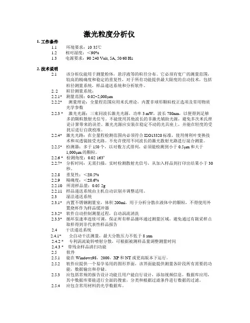
激光粒度分析仪1. 工作条件1.1 环境要求:10-35℃1.2 相对湿度:<90%1.3 电源要求:90-240 Volt, 5A, 50/60 Hz2. 技术说明2.1该分析仪能用于测量粉体,悬浮液等的粒径分布。
它必须有宽广的测量范围,较高的精确度和稳定的重复性,对于所有功能提供最大限度的自动技术,包括粒径测量系统,样品递送系统和分析软件。
2.2 粒径测量系统;2.2.1* 测量范围:0.02~2,000μm2.2.2* 测量理论:全量程范围应用米氏理论,内置非球形颗粒校正选项及常用物质光学参数2.2.3 * 激光光源:三束同波长激光光源,功率3 mW,波长780nm,以便得到足够多的颗粒散射光信号。
不能使用其他波长的非激光辅助光源,避免多次米氏理论计算带来的误差。
激光光源应安装在稳定不动的光具座上,并能在轻度的受扰后进行自我校准。
2.2.4* 激光光路:在全量程检测范围内必须符合ISO13320标准,使用傅利叶变换技术和双透镜接受光路。
不允许使用不同波长的激光散射光路进行混合测量。
2.2.5* 检测器:多于150个,以对数方式排列,必须能检测到小于0.5μm和大于1,000μm的颗粒。
2.2.6 * 检测角度:0.02-163º2.2.7* 分析时间:无需扫描,实时检测散射光信号,从加入样品到打印出结果小于30秒。
2.2.8 重复性:<±0.5%2.2.9 精确度:<±0.6%2.2.10 所需样品量:0.05-2g2.2.11 样品递送系统由主机自动识别并调整适用。
2.3 湿法递送系统2.3.1* 内置不锈钢测量室,体积200ml,用于分析分散在液体中的颗粒,不得使用外置烧杯作为样品缓冲器2.3.2* 软件自动控制测量过程,自动涡流清洗2.3.3* 循环泵速率连续可调,保证所有样品循环通过测量区域,避免通过有限采样点取样得到非代表性样品报告2.4 干法递送系统2.4.1* 全自动干法测量,最大分散压力不低于8 atm2.4.2 * 专利涡流旋转喷射分散,可根据被测样品量调整测量时间2.4.3 * 带残余样品清扫功能2.5 软件2.5.1 能在Windows98,2000,XP和NT或更高版本下运行。

laPart iclesize analys is-Laserdiffra ction method s(ISO-13320-1)Introd uctio nLaser diffra ction method s are nowada ys widely used for partic le sizing in many differ ent applic ation s. The succes s of the techni que is based on the tact that it can be applie d to variou s kindsof partic ulate system s, is fast and can be automa ted and that a variet y of commer cialinstru ments i s availa ble. Nevert heles s, the proper use of the instru mentand the interp retat i on of the result s requir e the necess ary cautio n.Theref ore, there i s a need for establi shin g an intern ation al standa r d for partic l e size analysi s by laserdiffra ction method s. Its purpose i s to provid e a method ol ogy for adequa te qualit y contro l in partic l e size analysis.Histor icall y, the laserdiffra ction techni que starte d by taking only scatte ri ng at small angles into consid erati on and, thus, has been knownby the followi ng names:-fraunh oferdiffra cti on;-(near-) forwar d lightscatte ring;-low-angle l aser light scatte ring (LALLS).Howeve r, the techni que has been broade ned to include lightscattering in a wider angula r range and applic a tion of the Mie theory in addition to approx i mati ng theori es such as Fraunh ofer and anomal ous diffraction.The laserd iffra ction techni que is basedon the phenom enon that particles scatte r light in all direct i ons with an intensity patter n that is dependent on partic l e size. All presen t instru ments assume a spheri cal shape f or the partic l e. Figure1 illust rates the charac teris ticsof single partic lescatte ringpatter ns: altern ation of high and low intens ities, with patter ns that extend for smalle r partic les to wider angles than for larger particles[2-7,10,15 in the biblio g raph y].Within certai n limits the scatte ri ng patter n of an ensembl e of particles is identi cal to the sum of the indivi dualscatte ringpatter n s of all partic les presen t. By using an optica l model to comput e scatte ring f or unit volume s of partic l es in select ed size classe s and a mathem atica l deconvoluti on proced ure, a volume tricpartic le size distri butio n is calcul ated, the scatte ringpatter n of which fits best with the measur e d patter n (see also annex A).A typica l diffra ction instru m entconsis t s of a lightbeam (usuall y a laser), a partic ulate disper singdevice, a detect or for measuri ng the scatteringpatter n and a comput er for both contro l of the instru ment and calculation of the partic l e size distri butio n. Note that the laserdiffra ction technique cannot di stin gui sh betwee n scatte ri ngby single partic l es and scatteringby cluste r s of primar y partic l es formin g an agglom erate or an aggreg ate. Usuall y, the resulti ng partic l e size for agglom erate s is relate d to the cluste r size, but someti mes the size of the primar y partic l es is reflected in the partic l e size distri butio n as well. As most partic ulate sample s contai n agglom erate s or aggreg ates and one is genera lly intere sted in the size distri butio n of the primar y partic l es, the cluste r s are usuall y dispersed into primar y partic l es before measur ement.Histor i call y, instru ments only used scatte ring angles smalle r than 14°,which limite d the applic a tion to a lower size of about 1μm. The reason for this limita ti on i s that smalle r partic l es show most of theirdistinctive scatte ring at larger angles (see also annex Z).Many recent instruments allow measur ement at larger scatte ri ng angles, some up to about150°,for exampl e throug h applic a ti on of a conver ging beam, more or larger lenses, a second laserbeam or more detect ors. Thus smalle r particles down to about 0.1μm can be sized. Some instru ments i ncorp orate additi onal i nform ati on from scatte ring i ntensities and intensity differ ences at variou s wavele ngths and polari zatio n planes in order to improv e the charac teriz ati on of partic l e sizes in the submic r ometre range.Partic l e size analysis – Laser diffra ction m ethod s-Part 1:Genera l princi ples1 scopeThis part of ISO 13320provid e s guidan ce on the measur ement of size distri butio n s of partic l es in any two-phase system, for exampl e powder s, sprays, aerosol s, suspen si ons, emulsi ons and gas bubble s in liquid s, throug h analysi s of their angula r lightscatte ring patter ns. It does not addres s the specif i c requir ement s of partic le size measur ement of specif i c produc t s. This part of ISO13320 is applic a ble t o partic l e sizesrangin g from approx i mate ly 0.1μm to 3μm.For non-spheri cal partic l es, an equiva lent-sphere size distri butio n is obtain e d becaus e the techni que uses the assump tionof spheri cal partic l es in its optica l model. The resulti ng partic l e size distri butio n may be different from thoseobtain e d by method s basedon otherphysic al princi ples(e.g. Sedime ntati on, sievin g).3,terms, defini tions and symbol sFor the purpos es of this part of ISO 13320, the follow ing terms, defini ti ons and symbol s apply.3.1 terms, defini ti ons3.1.1 absorp ti onintrodu ctio n of intensi ty of a lightbeam traver singa medium throug h energy conver si on i n the medium3.1.2 coeffi cient of variati on (变异系数)Noativ e measur e(%) for precis i on: standa rd deviat ion divide d by mean value of popula ti on and multip l ied by 100 or normal di stri butio n s of data the median is equal t o the mean3.1.3compl ex refrac tive i ndex(Np)Refrac tive i ndexof a partic l e, consis tingof a real and an imagin ary (absorp tion) part.Np=n p-ik p3.1.4 relati ve refractive index(m)comple x refrac tive i ndexof a partic l e, relati ve to that the medium。