ARD2系列智能电动机保护器说明书(三)
- 格式:pdf
- 大小:8.04 MB
- 文档页数:10
How to configure, monitor, and control Motor Insight via Modbus, DeviceNet, and PROFIBUSApplicationMotor Insight T is an advanced motor protective relay with thermal motor overload, supply,and load protection; configurable ground fault detection; power monitoring; an intuitive user interface; and optional communications. The optional communications allow for remote control and reset of faults, and remote monitoring of numerous operating and configuration parameters. The communication modules also include inputs that can be usedto bring the status of sensors or switches backto the system controller, as well as outputs to control the contactor or turn on pilot lights.OverviewThe industrial networks supported by the Motor Insight relay are all open networks. This means that there are many software tools already available that can be used to configure the device over these networks. Each of the supported networks will be discussed in this document, including suggestions for various configuration tools, many of which are free downloads from the Internet. In many cases, the network tools supplied by the manufacturerof the network master can be used to configure any device on that network.Overview of Modbus T, DeviceNet E and PROFIBUS TFor most applications, the Motor Insight relay parameters can be easily configured using its intuitive user interface. Then, the communication network master can be used to control and monitor the device during operation. This network master reads status information from each slave device and writes control information. The communication interface modules forMotor Insight allow control for the following:1. Remote reset of a fault2. Remote trip3. Control of on-board field outputs Numerous parameters are available to be monitored from Motor Insight, including:1. Device status bits2. rms current IA3. rms current IB4. rms current IC5. rms current average6. rms voltage VAB7. rms voltage VBC8. rms voltage VCA9. rms voltage average10. Total kW11. Voltage unbalance percent12. Current percent13. Apparent power factor14. Residual ground current deciamps15. Frequency16. Overload thermal pile17. Trip reason18. Overload status19. Error code20. Field inputsThe following is a discussion concerning the third-party software tools available for the open networks supported by Motor Insight. ModbusMotor Insight supports both Modbus RTU and Modbus ASCII modes, as well as baud rates from 9600 to 115.2K baud. It will communicate with any Modbus master.The unique aspect of Modbus is that special configuration tools are typically not necessaryas they are with many other industrial networks. The reason is that Modbus requires Modbus Data Register addresses for all parameters in all Modbus devices. This allows a Modbus master to easily read and write data to a Modbus slave device for configuration, control, and monitoring purposes. Motor Insight is no different. It has assigned a Modbus Data Address to all available parameters. This information is publishedin the Motor Insight overload and monitoring relays user manual, publication MN04209001E.Eaton Corporation Electrical Sector1111 Superior Ave. Cleveland, OH 44114United States877-ETN-CARE (877-386-2273) © 2010 Eaton CorporationAll Rights ReservedPrinted in USAPublication No. AP04209004E / Z9775 August 2010PowerChain Management is a registered trademark of Eaton Corporation.All other trademarks are property of their respective owners.Application Paper AP04209004E Effective August 2010How to configure, monitor, and control Motor Insight via Modbus, DeviceNet,and PROFIBUSIf a third-party Modbus software package is desired to configureor verify the configuration or operation of Motor Insight, there are numerous software tools available. Many of these tools are free downloads, such as ModScan. Others can be found by simply searching the Web for Modbus Software Tools.Eaton has a line of electronic operator interface devices called HM i.A program for a 4-inch HM i is available as a free download from /motorinsight or via this direct link. This program communicates via Modbus to multiple Motor Insight devices. It contains screens for configuring, monitoring, and controlling upto 16 Motor Insights from a single HM i. To obtain the HM i software needed to download the program to an HM i, visit / electrical. Then, click the “Tools & Downloads” link. Next, select “Software Downloads.” On the next page, under the Products drop-down, select “Operator Interface...” and then select “HM i Operator Interface Configuration Software.” Also note that the HM i software allows for changing the HM i program so it can be downloaded to any size HM i: 4-, 6-, 8-, or 10-inch unit.Another source of available Modbus tools can be found on the official Modbus Web site: .DeviceNetUnlike Modbus, where all parameters in a device have a data address assigned to them, DeviceNet slave devices use input and output assemblies. Each input assembly will include the same status bits indicating operational status of the device. The various input assemblies differ by the additional data that can be monitored with each. The Motor Insight relay has five different input assemblies. Two of these input assemblies allow the user to select the parameters to monitor. The various output assemblies are for control. They provide the ability to reset faults, trip the overload, and turn the outputs on-board the DeviceNet module on and off. DeviceNet is an open network that requires a software tool to configure slave devices and to map their data into the scan list of the master. The manufacturer of the DeviceNet master will provide a software tool to map slave devices into the scan list of the master so the system controller can control and monitor each Motor Insight. Motor Insight contains an intuitive user interface for configuration, but when on a DeviceNet network, it can be configured by any third-party DeviceNet commissioning tool as well. The DeviceNet specification requires that all DeviceNet products have an eds file (electronic data sheet). This file is a text file that is used to uniquely define each parameter in the device. DeviceNet commissioning tools are designed with the ability to import eds files for any valid DeviceNet slave device. The software tool can then be used to configure the device. There are two eds files and an icon file available for Motor Insight. They may be downloaded from/motorinsight. These files can then be imported into any valid DeviceNet commissioning software, such as:1. Eaton’s CHStudio E2. Eaton’s ELCSoft (DNET CONFIG Tool)3. Rockwell’s RSNetWorx E for DeviceNetCHStudio is a free download from the Eaton Web site; searchfor CHStudio and download the software and activation code.It can be used to configure any DeviceNet slave device, but notthe network master.ELCSoft is the programming software for the Eaton PLC line called ELC. This PLC line includes a complete DeviceNet master, the ELC-CODNETM module. The commissioning software is included in the ELCSoft programming software. It can configure any DeviceNet slave device by importing the eds file for the device and can fully configure the ELC-CODNETM DeviceNet master module.The manufacturer of the network master typically supplies the software tools needed to configure the master. RSNetWorxfor DeviceNet can be purchased from Rockwell or a Rockwell distributor. Motor Insight eds files can be imported into RSNetWorx for DeviceNet, allowing the software to configurethe Motor Insight and a Rockwell DeviceNet master.Once all slave devices on a DeviceNet network have been configured and mapped into the DeviceNet master’s scan list, the master will continuously poll the slave devices, like the Motor Insight, writing control data to them and monitoring various parameters. Motor Insight has more data available to monitor than any other overload relay of its type. This information is published in the Motor Insight overload and monitoring relay user manual, MN04209001E.Another source of available DeviceNet tools can be found on the official DeviceNet Web site: .PROFIBUSPROFIBUS is very similar to DeviceNet in that the network configuration tools are typically supplied by the manufacturer of the PROFIBUS master. There is also a file for PROFIBUS similar to the eds file for DeviceNet, called a GSD file. All valid PROFIBUS slave devices must have a GSD file. This file is imported into the PROFIBUS commissioning tool or the programming software, allowing the software to configure the device and map its I/O data so the PROFIBUS master can poll the slave devices for control and monitoring purposes. These PROFIBUS tools are supplied bythe manufacturer of the PROFIBUS master. The GSD file may be downloaded from /motorinsight. This file can then be imported into any valid PROFIBUS software tool, such as Siemen’s SIMATIC Software. Other PROFIBUS network product vendors are Woodhead Connectivity, Bihl+Wiedemann GmbH and PROCENTEC. Another source of available PROFIBUS tools can be found on the official PROFIBUS Trade Organization Web site: /.Supporting documentationMotor Insight User Manual MN04209001E Motor Insight DeviceNet Instructional Leaflet IL04209005EMotor Insight Modbus Instructional Leaflet IL04209004EMotor Insight PROFIBUS Instructional Leaflet IL0420900XEELC System Manual MN05003003EELC-CODNETM Instructional Leaflet IL05001003EHM i User manual MN04802014EAdditional helpIn the event that additional help is needed, please contact the Technical Resource Center at 1-877-ETN-CARE (386-2273).。
数显式电机保护器
一、功能简介:
1、反时限
2、手动(即时)/断电复位
3、可显示三相最大电流值
4、数字显示故障原因,便于处理故障
5、调节电流及时间旋钮时,可准确显示电流及时间设定值
6、过电流/堵转/缺相/不平衡/反相保护
7、显示部分与主体可分离,便于在面板上安装和操作
见附图2。
四、安装调试
1、将保护器固定在交流接触器旁,A1、A2接操作电源,主回路相线按R、S、T相序对
应穿过保护器的三相互感器,辅助触点接线端子95、96按接线图(附图3)连接。
2、调试方法
根据反时限特性和实际启动时间,保护设置时间=实际启动时间╳(110~120%)设
置后电机按所设特性脱扣,启动为冷态,启动后按照热态,具体参看说明书反时限脱扣特性曲线。
3、设置负载电流及过载延时
①调节“电流设定”旋钮,此时显示体上显示负载电流设定值,将负载电流设定
至电机额定电流的110%.
②调节“时间设定”旋钮,此时显示体上显示过载电流设定值,将过载延时设定
至电机启动所需的时间。
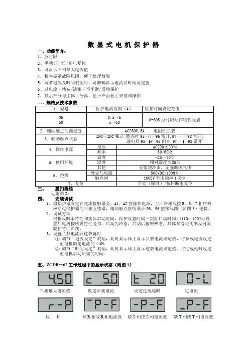
五、ZCDB-62工作过程中的显示状态(附图1)
三相最大电流值设定负载电流设定过载延时过电流
缺R相或R相电流低缺S相或S相电流低缺T相或T相电流低反相
六、ZCDB -62反时限特性曲线(附图2)
七、接线图(附图3)
热态 冷态 5S 10S 20S 30S 60S 5S 10S 20S 30S 60S 1000%。

0731-汤经理WDB-FST电动机智能保护器、AA说明书0731-汤经理AQ0OSENDIANQIWDB-FST智能电动机保护器⑧家质h【认证企业国索强制性认证(3C)及!£09^01:硬■誉踵傅乘认证电动机保护器订购热线:*************0731-汤经理一、概述我公司是一家从事于电动机保护器科研、生产、销售、技术支持的高新技术企业。
对电动机的保护有着深入的研究,本公司生产的电动机保护器具有低价、物美、品种齐全,性能卓越深受用户的喜爱。
电动机保护器从产品品种上分为四种。
1基本型,2基本智能型,3智能豪华型,4普通实用型。
本产品核心部件均采用美国MICRHIP公司新型十六位单片机及控制器配低功耗集成电路开发而成的,该保护器0731-汤经理具有保护功能齐全,测量参数直观,反应灵敏,动作及时可靠,工作稳定可靠、精度高、保护参数设定简单方便和数字化、智能化、网络化等特点,可满足不同层次用户的要求。
广泛应用于电力、石油、治金、化工、纺织等工业电动机及三相电力系统。
作过热、过载、欠载、断相、过压、欠压、堵转、三相电路不平衡保护。
还通过本机RS-485远程通迅接口和PC组成网络监控系统,通过PC对监控器保护参数进行修改及运行状态控制。
是一种提高电机运行安全和自动化管理水平的智能化仪器,可以与上位机通迅构成远程监控与一体的高新技术产品。
二、主要特点采用先进的微机技术与高性能的集成芯片,整机功能强大、性能优越。
测试精度高,线性度好,分辨率高,整机抗干扰能力强,保护动作可靠。
三相电流值,电压值及各类故障代号,显示于LED上、直观清晰。
稳定性好,长期工作无须维护。
采用E2PR0M存储技术,实现参数设定,掉电后设定参数仍保存下来,勿须再设定。
一机多用,可取代传统的电流互感器、电流表、电压表、热继电器和时间继电器等。
配有RS485串行数字接口,便于上位机(PC)进行数字通迅。
三、 依据电动机制造商的规范和过程控制要求设置预警和脱扣参数图1主要功能 保护功能:除了具有通用的保护功能外,还有自启动、通迅启动和关闭,且欠流、过压、欠压、三相电流不平衡、自启动等功能用户可取可舍。
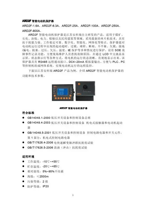

ARD2智能电动机保护器
引言由于生产自动化及各种自动控制、顺序控制设备的出现,要求电机经常运行在频繁的起动、制动、正反转、间歇以及变负荷等方式,电机的运行要求越来越高,运行环境也越来越苛刻,同时,由于电机与配套机械连在一起,当电机发生故障时,经常波及生产系统。
因此,对电机实行有效的保护是保证生产系统正常工作的一项重要任务。
本文将要介绍的是ARD2 型电动机保护器的经济、简洁的设计方法和应用。
该型保护器主要用于对电动机运行状态的监测,并针对电动机在生产运行过程中出现的启动超时、欠压、过压、欠载、过载、短路、堵转/阻塞、断相、不平衡、剩余电流(接地/漏电)等故
障进行保护,使电动机不至于因为以上原因而导致损坏,从而使生产遭受损失,采用ARD2 电动机保护器能有效提高电动机运行的安全性,降低生产损失,是传统热继电器的理想替代品。
1技术指标ARD2 型智能电动机保护器的技术指标见表1。
表1
2设计方法目前市场上综合型的智能电动机保护器的设计主要采用交流采样方式+高性能单片机的方案,采用该设计方法的电动机保护器测量参数多、测量精度高、能够提供更完善的保护功能,但是采用此设计方法的成本较高,销售价格也高,在只需要对电动机提供过载、断相等基本常见故障保护的场合没有性价比可言。
因此采用一种设计简单、功能能够满足基本保护要求、主要用于替代热继电器的智能电动机保护器将会有很大的市场。
ARD2 型保护器就是一款设计简洁,保护功能较多,能够满足大多数电动机保护要求的经济型的智能电动机保护器。
ARD2 型智能电动机保护器采用低成本的设计方案,整体系统由信号处理单元、中央处理单元、电源模块、人机交互单元、人。

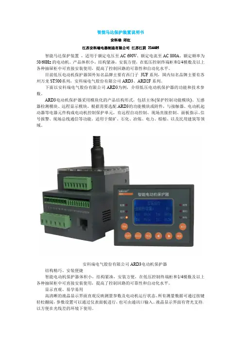
428ARD3M智能电动机保护器使用说明书V1.2安科瑞电气股份有限公司ACREL Co.,Ltd申明版权所有,未经本公司之书面许可,此手册中任何段落,章节内容均不得被摘抄、拷贝或以任何形式复制、传播,否则一切后果由违者自负。
本公司保留一切法律权利本公司保留对本手册所描述之产品规格进行修改的权利,恕不另行通知。
订货前,请垂询当地代理商以获悉本产品的最新规格。
目录1、概述 (1)2、产品特点 (1)3、型号说明 (2)4、主要参数 (3)5、外形尺寸及安装 (5)6、保护功能说明 (12)7、功能设置与说明 (27)8、通讯设置与说明 (42)9、典型应用方案 (82)10、特色功能简介 (87)11、订货范例 (89)1、概述ARD3M智能电动机保护器(以下简称保护器)适用于额定电压至660V的低压电动机回路,集保护、测量、控制、通讯、运维于一体。
其完善的保护功能确保电动机安全运行,带有逻辑可编程功能,可以满足多种控制方式。
可选配不同通讯模块适应现场通讯需求。
该产品采用分体式结构,由主体、显示单元、互感器和选配的通讯模块组成,可适应各种柜体的安装。
产品执行标准:——GB14048.4-2010低压开关设备和控制设备第4-1部分:接触器和电动机起动器机电式接触器和电动机起动器(含电动机保护器);——JBT10736-2007低压电动机保护器。
2、产品特点■辅助电源类型可选,AC220V电源模块支持电源范围AC85-265V/DC100-300V,AC380V 电源模块支持电源范围AC/DC100-415V。
■支持基波和全波电力参数测量(U、I、P、Q、S、PF、F、EP、EQ),电压及电流不平衡度,电压、电流正序、负序、零序分量,三相电压相角,剩余电流,电压、电流2-63次分次谐波测量,分次谐波含有率及总谐波畸变率。
■保护功能包括过载反时限、过载定时限、接地、起动超时、漏电、欠载、断相、堵转、阻塞、短路、溢出、不平衡(电流、电压)、过功率、欠功率、过压、欠压、相序、温度、tE 时间、外部故障、起动次数限制、运行时间报警、故障次数报警。

ARD3系列智能电动机保护器
佚名
【期刊名称】《电器工业》
【年(卷),期】2007(000)005
【摘要】ARD3系列智能电动机保护器(以下简称保护器),是由上海安科瑞电气有限公司和上海电器科学研究所共同开发的,为额定工作电压至660V,额定电流至800A的电动机提供完善保护的新一代智能化、网络化、数字化的电动机保护器,保护器对电动机的过载,堵转、阻塞、欠载、温度、断相、不平衡、相序、欠压、过压、欠功率、接地或漏电等故障导致的危害加以保护,最大限度地保证设备运行的可靠性与安全性.其集测量、保护、监视、控制于一体。
具备完善的网络通讯功能.可与接触器、电动机起动器等电器元件构成电动机控制保护单元,适用于石化、电力、煤矿、冶炼、铁路以及民用建筑等领域。
【总页数】1页(P58)
【正文语种】中文
【相关文献】
1.新产品信息——-ARD3系列电动机保护器 [J],
2.上海安科瑞电气有限公司(新产品信息)——ARD3系列电动机保护器 [J],
3.安科瑞ARD3系列电动机保护器 [J],
4.ARD3系列电动机保护器 [J],
5.ARD3系列电动机保护器 [J], 张婷
因版权原因,仅展示原文概要,查看原文内容请购买。
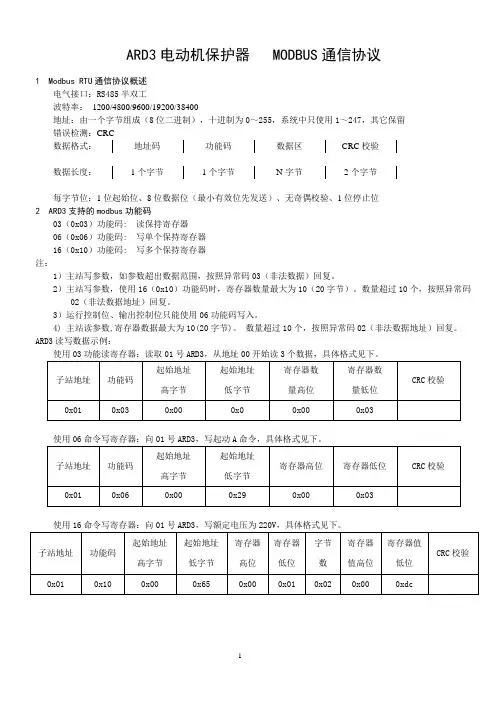
ARD3电动机保护器 MODBUS 通信协议1 Modbus RTU 通信协议概述电气接口:RS485半双工波特率: 1200/4800/9600/19200/38400地址:由一个字节组成(8位二进制),十进制为0~255,系统中只使用1~247,其它保留 错误检测:数据格式:数据长度:每字节位:1位起始位、8位数据位(最小有效位先发送)、无奇偶校验、1位停止位 2 ARD3支持的modbus 功能码03(0x03)功能码: 读保持寄存器 06(0x06)功能码: 写单个保持寄存器 16(0x10)功能码: 写多个保持寄存器 注:1)主站写参数,如参数超出数据范围,按照异常码03(非法数据)回复。
2)主站写参数,使用16(0x10)功能码时,寄存器数量最大为10(20字节)。
数量超过10个,按照异常码02(非法数据地址)回复。
3)运行控制位、输出控制位只能使用06功能码写入。
4) 主站读参数,寄存器数据最大为10(20字节)。
数量超过10个,按照异常码02(非法数据地址)回复。
ARD3读写数据示例:3 ARD3智能型电动机保护器通讯地址表3.1 ARD3智能型电动机保护器通讯地址名称及地址如表1所示。
表1 ARD3智能型电动机保护器通讯地址名称及地址注:1)地址201~227、512~959为本公司内部使用地址,用户没有专用的仪器不得修改。
3.2 故障记录历史故障记录从EEPROM的256字开始,直到767字,EEPROM容量小于256字时,不做历史记录。
记录空间循环使用,最近的记录将覆盖最老的记录,每次故障的记录包括64个字节(即32个16位的字),本产品包括8组故障记录。
具体结构如表2所示。
表2 故障记录结构表3.3 实时时钟和固件信息ARD3智能型电动机保护器的故障记录功能带有实时时钟信息,实时时钟和固件信息结构详见表3所示。
表3 实时时钟和固件信息结构表4 异常应答4.1 非法功能 01主站询问报文格式:本协议没有用到0x08功能码,因此子站应答:4.2 非法数据地址02主站询问报文格式:06功能码寄存器地址错误,因此子站应答:4.3 非法数据值03主站询问报文格式:16功能码寄存器数值超过参数范围,视为数值错误,因此子站应答:11。

三相ARD系列电梯停电自救援装置使用说明书版本号:V1.1目录第1章产品介绍 (2)1.1 型号说明 (2)1.2 铭牌说明 (2)1.3 标准规格 (3)1.4 产品选型 (3)1.5 外型尺寸 (4)第2章接线 (5)2.1 ARD3PXX应用接线 (5)2.2 ARD3TXX应用接线 (5)第3章使用方法及维护 (6)3.1 工作原理 (6)3.2 操作面板 (6)3.2.1 LED指示灯定义 (6)3.2.2 操作按钮和开关 (6)3.2.3 显示面板 (7)3.3 更换电池指导 (8)第1章产品介绍本章对电梯停电自救援装置(以下简称自救援装置)的型号、规格、外型尺寸等进行介绍。
1.1 型号说明自救援装置的型号说明如图1.1所示(以普通型15KW为例)。
自救援产品类型A:有电池型救援时最大适配电机功率3:三05kW – 30kW电压类型P:普通型T:重载型图1.1型号说明示意图注1:目前可提供3P和3T两种机型:输入电压和输出电压都是三相380V,要求输入电源必须要有N线。
注2:普通型要求控制系统有应急救援功能,ARD状态下能自动向重载方向救援;重载型只要求控制系统断电再上电有就近平层功能。
1.2 铭牌说明铭牌示意图如图1.2所示。
铭牌上记录了ARD系列自救援装置的型号、功率、输入、输出、序列号(即制造编号)、条形码等信息。
铭牌粘贴在ARD系列自救援装置的右侧面。
S/N: XXXXXXXX-XXXXXXXXXXX-XX图1.2铭牌说明示意图1.3 标准规格表1.1标准规格表1.4 产品选型表1.2 3P系列选型表(外网电源类型:3-PH AC380V,救援时提供三相AC380V)表1.3 3T系列选型表(外网电源类型:3-PH AC380V,救援时提供三相AC380V)注:1. 表1.2~1.3中所列输出功率为额定输出功率,可以短时提供2~3倍的过载输出;2.表1.2~1.3中所列额定载荷适用于异步机或者同步机2:1曳引比;3.对于同步机4:1曳引比梯型,额定载荷可以提高到标称值的1.8倍,例如,上表中ARD3P15A的2:1曳引比额定载荷为1150KG,则其4:1曳引比的额定载荷约为2000KG;4.对于同步机1:1曳引比梯型,额定载重需升一档选取;5.对于卷扬式(强驱式)电梯,选型时请咨询我司技术部。
ard2智能电动机保护器的设计与应用摘要:介绍一款经济型智能电动机保护器-ARD2型的设计与应用,该保护器将众多保护功能集于一体,针对电动机在实际使用中会遇到的多种故障进行保护,使电机在各种故障条件下不会产生损坏,提高电动机运行的可靠性,减少由于电动机的故障问题带来的生产损失。
关键字:电动机保护器,ARD2型,保护功能,经济型引言本文将要介绍的是ARD2型电动机保护器的经济、简洁的设计方法和应用。
该型保护器主要用于对电动机运行状态的监测,并针对电动机在生产运行过程中出现的启动超时、欠压、过压、欠载、过载、短路、堵转/阻塞、断相、不平衡、剩余电流(接地/漏电)等故障进行保护,使电动机不至于因为以上原因而导致损坏,从而使生产遭受损失,采用ARD2电动机保护器能有效提高电动机运行的安全性,降低生产损失,是传统热继电器的理想替代品。
1 技术指标ARD2型智能电动机保护器的技术指标见表1。
2 设计方法ARD2型智能电动机保护器采用低成本的设计方案,整体系统由信号处理单元、中央处理单元、电源模块、人机交互单元、人机界面、控制模块、通讯接口模块等构成,装置硬件结构如图1所示。
2.1信号处理单元信号处理单元采用整流放大滤波电路,该电路能将采样得到的交流信号整流成直流信号,由CPU片内AD进行转换计算。
图中IC1为运算放大器LM324,采用双电源供电,这样可以保证LM324输出电压达到5V充分利用A/D转换提高显示精度。
IC1将采样得到的信号进行两级放大处理,提高了信号的采样精度,保证了信号的线性度。
2.2 中央处理单元中央处理单元选用MOTOROLA公司的第一款基于高度节能型S08核的器件MC9S08AW32高性能单片机,该单片机片上资源丰富,抗干扰能力突出。
内含32K字节用户程序空间,片上集成2K的RAM,支持BDM片上调试功能,片内集成看门狗电路,片上集成8通道10位AD。
外部扩展了铁电存储器,用于存储一些重要的参数,即使以后升级程序也不会丢失先前的重要数据。
ARD2系列智能电动机保护器安装使用说明书上海安科瑞电气有限公司目录一、概述 (1)二、产品型号 (2)三、通用技术指标 (3)四、外型尺寸及安装 (3)五、显示与用户编程 (9)六、接线方式 (13)七、通讯协议 (15)八、系统应用方案 (28)九、保护功能说明 (32)十、注意事项 (37)十一、订货范例 (38)一、概述ARD2系列智能电动机保护器(以下简称保护器),采用最新的单片机技术,具有抗干扰能力强、工作稳定可靠、数字化、智能化、网络化等特点。
保护器能对电动机运行过程中出现的起动超时、过载、断相、不平衡、欠载、剩余电流(接地/漏电)、堵转、过压、欠压等多种情况进行保护,并设有SOE故障事件记录功能,方便现场维护人员查找故障原因。
适用于煤矿、石化、冶炼、电力、船舶、以及民用建筑等领域。
本保护器具有RS485远程通讯接口,4~20mA模拟量输出,方便与PLC、PC等控制机组成网络系统。
实现电动机运行的远程监控。
二、产品型号ARD 2—/附加功能(表2)起动方式:A—直接起动额定电流(表1)设计序列号企业代号:安科瑞电气有限公司互感器额定电流(A)互感器匝数(一次)整定电流Is范围(A)电动机功率(kW)1~~3 251~253~12100125~10012~55250163~25030~1328001250~800132~440表2附加功能代号附加功能代号远程起动Q4~20mA模拟量输出M 报警J4路开关量输入K通讯接口C SOE事件记录SR 漏电保护L三、通用技术指标表4技术参数技术指标保护器辅助电源AC220V/AC380V,功耗8VA电机额定工作电压AC380V,50Hz电动机额定工作电流6.3A(1.6A-6.3A)采用小型专用电流互感器测量模块25A(6.3A-25A)100A(25A-100A)250A(63A-250A)采用专用电流互感器800A(250A-800A)继电器输出3路,AC250V、3A;DC30V、3A ;开关量输入4路,光电隔离通讯RS485 Modbus协议SOE事件记录容量8个事件记录环境工作温度:-10ºC~55ºC贮存温度-20ºC~65ºC相对湿度5﹪~95﹪不结露海拔≤2000m污染等级2级防护等级IP20四、外形尺寸及安装4.1 外形及安装开孔尺寸正视图侧视图盘面开孔主体部分互感器部分(1~100A)互感器部分(100~250A )互感器部分(250~800A、零序互感器)安装方法主体部分安装互感器部分(~100A)安装安装连线拆卸连线250A以上互感器接线五、显示与用户编程显示说明表5序号名称状态功能说明1A相LED指示灯亮该指示灯亮则表明11显示的为A相电流2B相LED指示灯亮该指示灯则表明11显示的为B相电流3C相LED指示灯亮该指示灯亮则表明11显示的为C相电流4运行LED指示灯亮该指示灯亮则表明电动机正在运行5脱扣LED指示灯亮该指示灯亮则表明保护器脱扣继电器已动作6报警LED指示灯亮该指示灯亮则表明保护器报警继电器已动作7确定按键按下选择操作功能或返回上级菜单8左方向键按下察看事件或数字量减或移位9右方向键按下察看显示数据或数字量增10取消/复位键按下退出菜单或取消操作或将保护器复位114位LED数码管0000显示测量数值注A、B、C相指示灯全亮指示灯全亮则表明11显示的为三相平均电流按保护器上的“确定”键,至显示“P001”,按“”键和“”键用于菜单的选择,到相应的菜单序号后,按“确定”键,进入值域的设置,按“”键进行数据位的选择,按“”键用于数字的增加,所需参数设置完毕后,按“确定”键进行保存,再按“取消”键退出菜单。
ard2智能电动机保护器的设计与应用摘要:介绍一款经济型智能电动机保护器-ard2型的设计与应用,该保护器将众多保护功能集于一体,针对电动机在实际使用中会遇到的多种故障进行保护,使电机在各种故障条件下不会产生损坏,提高电动机运行的可靠性,减少由于电动机的故障问题带来的生产损失。
关键字:电动机保护器,ard2型,保护功能,经济型引言本文将要介绍的是ard2型电动机保护器的经济、简洁的设计方法和应用。
该型保护器主要用于对电动机运行状态的监测,并针对电动机在生产运行过程中出现的启动超时、欠压、过压、欠载、过载、短路、堵转/阻塞、断相、不平衡、剩余电流(接地/漏电)等故障进行保护,使电动机不至于因为以上原因而导致损坏,从而使生产遭受损失,采用ard2电动机保护器能有效提高电动机运行的安全性,降低生产损失,是传统热继电器的理想替代品。
1 技术指标ard2型智能电动机保护器的技术指标见表1。
2 设计方法ard2型智能电动机保护器采用低成本的设计方案,整体系统由信号处理单元、中央处理单元、电源模块、人机交互单元、人机界面、控制模块、通讯接口模块等构成,装置硬件结构如图1所示。
2.1信号处理单元信号处理单元采用整流放大滤波电路,该电路能将采样得到的交流信号整流成直流信号,由cpu片内ad进行转换计算。
图中ic1为运算放大器lm324,采用双电源供电,这样可以保证lm324输出电压达到5v充分利用a/d转换提高显示精度。
ic1将采样得到的信号进行两级放大处理,提高了信号的采样精度,保证了信号的线性度。
2.2 中央处理单元中央处理单元选用motorola公司的第一款基于高度节能型s08核的器件mc9s08aw32高性能单片机,该单片机片上资源丰富,抗干扰能力突出。
内含32k字节用户程序空间,片上集成2k的ram,支持bdm片上调试功能,片内集成看门狗电路,片上集成8通道10位ad。
外部扩展了铁电存储器,用于存储一些重要的参数,即使以后升级程序也不会丢失先前的重要数据。