CD74HC4518中文资料
- 格式:pdf
- 大小:47.54 KB
- 文档页数:8
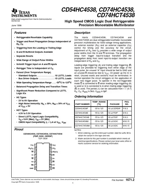
Pinout
CD74HC4518 CD74HC4520, CD74HCT4520
(PDIP, SOIC) TOP VIEW
1CP 1 1E 2
1Q0 3 1Q1 4 1Q2 5 1Q3 6 1MR 7 GND 8
16 VCC 15 2MR 14 2Q3 13 2Q2 12 2Q1 11 2Q0 10 2E 9 2CP
[ /Title (CD74 HC451 8, CD74 HC452 0, CD74 HCT45 20) /Subject
Features
Description
• Positive or Negative Edge Triggering
• Synchronous Internal Carry Propagation
Thermal Information
Thermal Resistance (Typical, Note 3)
θJA (oC/W)
PDIP Package . . . . . . . . . . . . . . . . . . . . . . . . . . . . .
90
SOIC Package . . . . . . . . . . . . . . . . . . . . . . . . . . . . .
• Wide Operating Temperature Range . . . -55oC to 125oC
• Balanced Propagation Delay and Transition Times
• Significant Power Reduction Compared to LSTTL Logic ICs
Ordering Information
PART NUMBER TEMP. RANGE (oC) PACKAGE
PKG. NO.
CD74HC4518E
-55 to 125
16 Ld PDIP E16.3
CD74HC4520E
-55 to 125
16 Ld PDIP E16.3
CD74HCT4520E
The Harris CD74HC4518 is a dual BCD up-counter. The Harris CD74HC4520 and CD74HCT4520 are dual binary up-counters. Each device consists of two independent internally synchronous 4-stage counters. The counter stages are D-type flip-flops having interchangeable CLOCK and ENABLE lines for incrementing on either the positive-going or the negative-going transition of CLOCK. The counters are cleared by high levels on the MASTER RESET lines. The counter can be cascaded in the ripple mode by connecting Q3 to the ENABLE input of the subsequent counter while the CLOCK input of the latter is held low.
元器件交易网
Data sheet acquired from Harris Semiconductor SCHS216 November 1997
CD74HC4518, CD74HC4520, CD74HCT4520
High Speed CMOS Logic Dual Synchronous Counters
CAUTION: Stresses above those listed in “Absolute Maximum Ratings” may cause permanent damage to the device. This is a stress only rating and operation of the device at these or any other conditions above those indicated in the operational sections of this specification is not implied.
CAUTION: These devices are sensitive to electrostatic discharge. Users should follow proper IC Handling Procedures.
Copyright © Harris Corporation 1997
-55 to 125
16 Ld PDIP E16.3
CD74HC4520M
-55 to 125
16 Ld SOIC M16.15
CD74HCT4520M
-55 to 125
16 Ld SOIC M16.15
NOTES:
1. When ordering, use the entire part number. Add the suffix 96 to obtain the variant in the tape and reethe component mounted on an evaluation PC board in free air.
DC Electrical Specifications
PARAMETER HC TYPES High Level Input Voltage
HC Types . . . . . . . . . . . . . . . . . . . . . . . . . . . . . . . . . . . . .2V to 6V HCT Types . . . . . . . . . . . . . . . . . . . . . . . . . . . . . . . . .4.5V to 5.5V DC Input or Output Voltage, VI, VO . . . . . . . . . . . . . . . . . 0V to VCC Input Rise and Fall Time 2V . . . . . . . . . . . . . . . . . . . . . . . . . . . . . . . . . . . . . . 1000ns (Max) 4.5V. . . . . . . . . . . . . . . . . . . . . . . . . . . . . . . . . . . . . . 500ns (Max) 6V . . . . . . . . . . . . . . . . . . . . . . . . . . . . . . . . . . . . . . . 400ns (Max)
Maximum Lead Temperature (Soldering 10s) . . . . . . . . . . . . . 300oC
(SOIC - Lead Tips Only)
Operating Conditions
Temperature Range, TA . . . . . . . . . . . . . . . . . . . . . . -55oC to 125oC Supply Voltage Range, VCC
Absolute Maximum Ratings
DC Supply Voltage, VCC . . . . . . . . . . . . . . . . . . . . . . . . -0.5V to 7V DC Input Diode Current, IIK
For VI < -0.5V or VI > VCC + 0.5V . . . . . . . . . . . . . . . . . . . . . .±20mA DC Output Diode Current, IOK
TRUTH TABLE
MR L L L L L L H
OUTPUT STATE Increment Counter Increment Counter
No Change No Change No Change No Change Q0 thru Q3 = L
2
元器件交易网 CD74HC4518, CD74HC4520, CD74HCT4520
For VO < -0.5V or VO > VCC + 0.5V . . . . . . . . . . . . . . . . . . . .±20mA DC Output Source or Sink Current per Output Pin, IO
For VO > -0.5V or VO < VCC + 0.5V . . . . . . . . . . . . . . . . . . . .±25mA DC VCC or Ground Current, ICC . . . . . . . . . . . . . . . . . . . . . . . . .±50mA
2. Wafer or die for this part number is available which meets all electrical specifications. Please contact your local sales office or Harris customer service for ordering information.
• Fanout (Over Temperature Range) - Standard Outputs . . . . . . . . . . . . . . . 10 LSTTL Loads - Bus Driver Outputs . . . . . . . . . . . . . 15 LSTTL Loads