VA车充规格书双口
- 格式:docx
- 大小:402.53 KB
- 文档页数:6
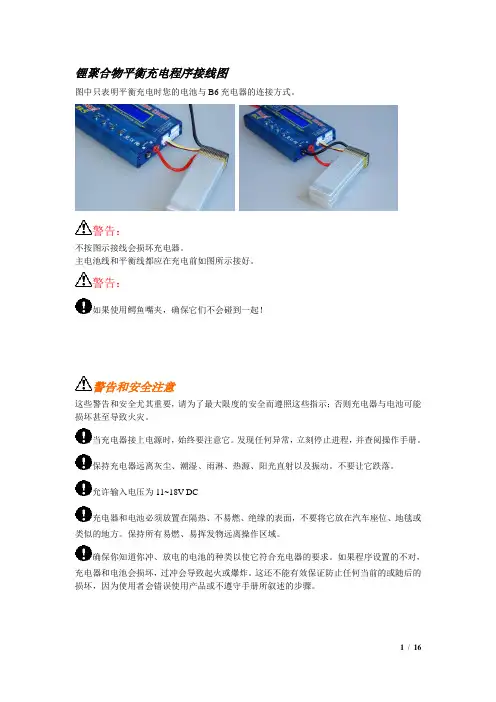
锂聚合物平衡充电程序接线图图中只表明平衡充电时您的电池与B6充电器的连接方式。
警告:不按图示接线会损坏充电器。
主电池线和平衡线都应在充电前如图所示接好。
警告:如果使用鳄鱼嘴夹,确保它们不会碰到一起!警告和安全注意这些警告和安全尤其重要,请为了最大限度的安全而遵照这些指示;否则充电器与电池可能损坏甚至导致火灾。
当充电器接上电源时,始终要注意它。
发现任何异常,立刻停止进程,并查阅操作手册。
保持充电器远离灰尘、潮湿、雨淋、热源、阳光直射以及振动。
不要让它跌落。
允许输入电压为11~18V DC充电器和电池必须放置在隔热、不易燃、绝缘的表面,不要将它放在汽车座位、地毯或类似的地方。
保持所有易燃、易挥发物远离操作区域。
确保你知道你冲、放电的电池的种类以使它符合充电器的要求。
如果程序设置的不对,充电器和电池会损坏,过冲会导致起火或爆炸。
这还不能有效保证防止任何当前的或随后的损坏,因为使用者会错误使用产品或不遵守手册所叙述的步骤。
NiCd/NiMH电压:1.2V/节允许的快充电流:1C~2C(取决于电池的性能)放电终止电压:0.85/节(NiCd),1.0V/节(NiMH)Li-ion电压:3.6V/节最大充电电压:4.1/节允许的快充电流:1C或更小最低放电终止电压:2.5V/节或更高LiPo电压:3.7V/节最大充电电压:4.2V/节允许的快充电流:1C或更小放电终止电压:3.0V/节或更高LiFe电压:3.3V/节最大充电电压:3.6/节允许的快充电流:4C或更小最低放电终止电压:2.0V/节或更高Pb电压:2.0V/节(铅-酸)最大充电电压:2.46/节允许的快充电流:0.4C或更小放电终止电压:1.75V/节或更高为避免充电线之间的短路,请总是先将充电电线插入充电器,再将它连上电池。
解除连接时使用相反的顺序。
在同一时间连接的电池包不要超过一个。
绝不要试图充或放以下种类的电池。
·包含有不同种类电池的电池包(包括不同生产商)。
01产品介绍02产品功能03安装方法
产品介绍
产品简介:
本产品由主控单元、人机交互、交流配电、输出控制、机箱等部分组成,提供刷卡支付、扫码支付与直充3种充电模式。
本产品广泛适用于各类大、中、小型公共停车场、新型商业区停车场、公司单位及小区内部停车场、私人停车位、充电桩运营企业等场所。
产品型号端口数支付方式
CDQC2SW
CD-企业代
号
QC-汽车交
流充电桩
1-1路输出
2-2路输出
Z-直充
S-刷卡支付
W-扫码支付
型号释义:
产品介绍
产品参数
额定电压:AC 220V 50Hz 额定电流:32A
额定功率:7KW
支付方式:直充/刷卡/扫码防护等级:IP54
通讯方式:4G模块输出端口:1路/2路
安装方式:壁挂/立柱
产品功能
产品优势1
234
56
充满保护
过流保护设置收费后台监控
语音提示空载断电产品功能
安装方法接线原理图
接线说明:
①、CDQC-1系列(单枪)、CDQC-2系列(双
枪)汽车交流充电桩输入零线、输入火线必须选
用大于等于6mm²及以上规格的铜导线;
②、接地线选用大于等于6mm²及以上规格的铜
导线;
③、CDQC-1系列(单枪)汽车交流充电桩建议
外接CDBLEi 2P C型 40A A型断路器或其他相同
规格断路器,CDQC-2系列(双枪)汽车交流充
电桩建议外接2只CDBLEi 2P C型 40A A型断路
器或其他相同规格断路器。
CDQC-1系列充电桩接线原理图CDQC-2系列充电桩接线原理图
谢谢!。
400v超充装技术参数
一、产品概述
400v超充装是一款高效、便捷的充电设备,专为电动汽车用户设计。
该产品采
用先进的充电技术,具备快速充电、大功率充电等特点,可大幅缩短充电时间,提高充电体验。
二、技术参数
1.额定电压:400V DC
2.最大充电电流:150A
3.最大充电功率:60kW
4.充电接口:CCS Combo
5.充电方式:快充、慢充可选
6.防护等级:IP54
7.工作环境温度:-20℃~50℃
8.储存温度:-40℃~70℃
三、产品特点
1.高效充电:采用先进的充电技术,大幅缩短充电时间,提高充电效率。
2.安全可靠:具备过流保护、过压保护、欠压保护等多重安全保护功能,确
保充电过程安全可靠。
3.便捷操作:支持快充、慢充两种充电方式,用户可根据实际需求选择。
4.适用性强:适用于多种电动汽车品牌,满足不同用户需求。
5.长寿命设计:采用高品质材料和严格的生产工艺,确保产品寿命长、稳定
性高。
6.智能管理:支持远程监控和智能管理,方便用户随时了解充电状态和设备
运行情况。
7.环保节能:采用绿色环保材料和节能设计,符合国家节能减排政策要求。
四、使用说明
1.将充电枪插入电动汽车充电口,确保连接紧密。
2.通过控制面板选择充电方式(快充或慢充)。
3.充电过程中,关注显示屏上的充电状态和电池电量。
Installation Manual and Operating InstructionsTA102 SeriesDual USB Charging PortTrue Blue Power® a division ofMid-Continent Instrument Co., Inc.Mid-Continent Instrument Co., Inc.dba Mid-Continent Instruments and Avionics9400 E. 34th Street N.Wichita, KS 67226 Manual number 9017942FOREWORDThis manual provides information intended for use by persons who, in accordance with current regulatory requirements, are qualified to install this equipment. If further information is required, please contact:True Blue Powerc/o Mid-Continent Instrument Co., Inc.Attn: Customer Service Dept.9400 E. 34th Street N.Wichita, KS 67226 USAPH (316) 630-0101FX (316) 630-0723We welcome your comments concerning this manual. Although every effort has been made to keep it free of errors, some may occur. When reporting a specific problem, please describe it briefly and include the manual part number, the paragraph/figure/table reference and the page number. Send your comments to:True Blue Powerc/o Mid-Continent Instrument Co., Inc.Attn: Technical Publications9400 E. 34th Street N.Wichita, KS 67226 USAPH (316) 630-0101FX (316) 630-0723All products produced by Mid-Continent Instrument, Co., Inc., including those identified as Mid-Continent Instruments and Avionics or True Blue Power, are designed and manufactured in Wichita, KS, USA.©Copyright 2017Mid-Continent Instrument Co., Inc.REVISION HISTORYRev. Date Approved Detailrelease.A 04/19/13 BAW InitialB 05/30/13 BMC Updates driven by internal review.C 08/22/13 TKV Added Circular Rear Mount option and kit details, addedconfigurations -2, -3, and -4.D 11/1/13 TKV Added two additional pins to installation kit and informationregarding a recommended crimp tool.E 11/14/13 TKV Added information about adhesive for Front Mount Kit.Added information about ETSO certification.F 06/10/14 TKV Changed information about mounting screws. (PT+0.285”was PT+0.312”)G 02/26/15 TKV Added Modification Information, Added Mod 1H 09/12/16 CAS Changed the weight in ‘1.2.2 Physical Attributes’ to 0.13pounds.J 01/04/17 BAW Updated to include new mounting option. Added 1.2.4.TABLE OF CONTENTS SECTION 1 GENERAL DESCRIPTION1.1 INTRODUCTIONSPECIFICATIONS1.2 TECHNICAL1.2.1 ELECTRICAL ATTRIBUTES1.2.2 PHYSICAL ATTRIBUTES1.2.3 QUALIFICATIONS1.2.4 CONFIGURATIONSSECTION 2 PRE-INSTALLATION CONSIDERATIONS2.1 COOLINGLOCATION2.2 EQUIPMENTCABLES2.3 ROUTINGOF2.4 LIMITATIONS2.5 MODIFICATIONSSECTION 3 INSTALLATION PROCEDURESINFORMATION3.1 GENERAL3.2 UNPACKING AND INSPECTINGHARNESS3.3 CABLE3.3.1 WIRE GAUGE SELECTION3.3.2 PIN ASSIGNMENT INFORMATION3.3.3 HARNESS VERIFICATION3.4 MOUNTINGCOMPLETION3.5 INSTALLATIONSECTION 4 OPERATION4.1 ELECTRICALPERFORMANCEFEATURES4.2 PROTECTIVE4.2.1 SHORT CIRCUIT PROTECTION4.2.2 OVER-CURRENT PROTECTION4.2.3 LOW INPUT VOLTAGE SHUTDOWN4.2.4 OVER-TEMPERATURESECTION 5 CONFORMANCE5.1 CONTINUED AIRWORTHINESS STATEMENT5.2 ENVIRONMENTAL QUALIFICATION STATEMENTSECTION 1 GENERAL DESCRIPTION1.1 INTRODUCTIONThe TA102 Series Dual USB Charging Port is a certified accessory that converts 10 to 32 volts of DC electrical input from the aircraft to standard 5V power for any electronic product that charges using a USB connector. The TA102 provides two Universal Serial Bus-A (USB-A) ports and can be rear mounted or front mounted in a variety of locations throughout the aircraft. The unit is certified to FAA TSO C71 and qualified to multiple RTCA DO-160 requirements, providing confidence and convenience to be mounted in either the cabin or cockpit.This Dual USB Charging Port is designed as a DCP (Dedicated Charging Port) to industry-standard protocol per the USB Battery Charging 1.2 Compliance Plan. Early-generation or smaller consumer electronics typically accept one (1.0) amp of power during charging. However, newer electronics, such as the Apple iPad®, other tablets and larger devices can accept and, in some cases, require up to 2.1 amps of power to charge and operate. As a high power DCP, the TA102 can provide up to 2.1 amps of power to charge any USB device, including the higher demand products. Unlike most dual USB chargers which provide one (1.0) amp on one port and 2.1 amps on the second port, the TA102 can provide 2.1 amps of power to both ports simultaneously. With features like short circuit protection, over-current protection, low voltage shut-down and temperature monitoring, it can handle unforeseen conditions safely.Small, compact and powerful, with plenty of installation flexibility, the TA102 is an ideal choice when selecting a highly useful and effective addition for any aircraft.1.2 TECHNICALSPECIFICATIONS1.2.1 Electrical AttributesInput Voltage: 10-32 VDCInput Power: 24 watts max; 1.7 amps @ 14 VDC / 0.85 amps @ 28 VDC Output Voltage: 5 VDC ±0.25 per portOutput Power: 2.1 amps max per portEfficiency: ~85%nominalTable 1.11.2.2 Physical AttributesWeight: 0.13poundsDimensions: (not including connector) 1.50 inches wide X 1.50 inches high X 0.96 inches deep Charging Ports Type: USB Standard-AMounting: Panel mount; rear or frontTable 1.21.2.3 QualificationsCertification: FAATSO-C71EASA ETSO-C71Environmental Qualification: (see section 5.2) RTCA DO-160G Environmental CategoryF1S2BB[(RCC1)(UG)]XXXXXXY[B(XX)]BRXXMXXXAX Table 1.31.2.4 ConfigurationsPart Number Power Input USB Connector6430102-1 Rear Sealed6430102-2 Bottom Sealed6430102-3 Rear Lighted6430102-4 Bottom LightedTable 1.4SECTION 2 PRE-INSTALLATION CONSIDERATIONS2.1 COOLINGNo external cooling is required. The unit will become warm when in use. This is normal and within operational parameters. No special mounting considerations are required; however, mounting to a metal surface can help dissipate any heat generated and extend the life of the product.LOCATION2.2 EQUIPMENTThe TA102 Dual USB Charging Port is designed for mounting flexibility, allowing for installation in the cockpit or in the cabin. It is designed for panel mounting and can be installed in a rectangular or circular rear mount configuration or, with an available installation kit, can be front mounted with a cosmetic cover plate. An instrument mounting adapter bracket is also available to easily mount the unit in a standard 2-inch round instrument opening that may already exist in the cockpit panel. There are two versions to choose from which allow the input connector to be located either on the rear of the unit or from the bottom.The unit can be mounted in any orientation. Clearance should be provided for the mating connector which may require an additional inch beyond the rear of the unit.OFCABLES2.3 ROUTINGAvoid sharp bends in cabling and routing near aircraft control cables. Avoid close proximity and contact with aircraft structures, avionics equipment or other obstructions that could chafe wires during flight and cause undesirable effects.2.4 LIMITATIONSEnvironmental qualifications were verified per RTCA DO-160, Revision G in lieu of those identified within the minimum performance standards (MPS) of the TSO.The conditions and tests for TSO approval of this article are minimum performance standards. Those installing this article, on or in a specific type or class of aircraft, must determine that the aircraft installation conditions are within the TSO standards, specification of the article and deviations as listed above. TSO articles must have separate approval for installation in an aircraft. The article may be installed only according to 14 CFR part 43 or the applicable airworthiness requirements.2.5 MODIFICATIONSEach model TA102 (part number 6430102-( )) has a nameplate that identifies the manufacturer, part number, description, certifications and technical specifications of the unit. It also includes the “MOD” or modification number representing notable changes in the hardware design of the unit. The following are descriptions of the current modification releases of the TA102 Dual USB Charging Port.MOD 0Modification (MOD) 0 is identified on the nameplate by the lack of marking on the MOD numbers 1 through 9 (i.e. 1-9 are visible).Mod 0 is the initial release of the TA102 Dual USB Charging Port.MOD 1Modification (MOD) 1 is identified on the nameplate by the marking/blacking out of MOD number 1 (i.e. 1 is not visible and 2-9 are visible see Figure 2.2 below for example).Mod 1 of the TA102 Dual USB Charging Port contains the following changes from MOD 0: -Main PC Board Thickness Changed to 0.062” (was 0.031”)MOD 0 MOD 1FIGURE 2.2Modification Nameplate ExamplesSECTION 3 INSTALLATION PROCEDURESINFORMATION3.1 GENERALThis section contains interconnect diagrams, mounting dimensions and other information pertaining to the installation of the TA102 Dual USB Charging Port. After installation of cabling and before installation of the equipment, ensure that power and ground are applied to the proper pins specified in Section 3.3.2, Pin Assignment Information.3.2 UNPACKING AND INSPECTING EQUIPMENTWhen unpacking this equipment, make a visual inspection for evidence of any damage that may have occurred during shipment. The following parts should be included:a. Dual USB Charging Port MCIA P/N 6430102-( )b. Installation Manual MCIA P/N 9017942c. Connector Kit MCIA P/N 9017960i. Mating Connector, 2-pinii. Pins (4) (2 required, 2 spares)iii. Screws, #4-40 x 1/4 flat-head (2)iv. Screws, #4-40 x 5/16 flat-head (2)Optional Equipment Available:a. Circular Rear Mount Installation Kit MCIA P/N 9017945b. Front Mount Installation Kit MCIA P/N 9017946c. Instrument Mount Adapter Kit MCIA P/N 9017947d. Rear Mount Installation Kit MCIA P/N 9017957Equipment Not Provided:a. Cable Harness Wire See Section 3.3.1 for specificationsb. Circuit Breaker Recommendation 2 amp (1 amp may be sufficient for 28V aircraft)(as needed per system requirements)HARNESS3.3 CABLEConstruct the cable harness following the instructions outlined below and per Figure 3.1.Refer to Section 2: Pre-Installation Considerations, for routing precautions.3.3.1 Wire Gauge SelectionUse of PTFE, ETFE, TFE, Teflon or Tefzel insulated wire is recommended for aircraft use.The wire harness should utilize 20-24 AWG stranded wire. Refer to table 3.1 below.Wire Gauge Wire Length20 AWG stranded wire 35 ft22 AWG stranded wire 22 ft24 AWG stranded wire 14 ftTable 3.1Wire Gauge and LengthNote: Pins should be crimped using Molex Hand Crimp Tool 63819-0000 (Preferred), 63811-2800 (obsolete) or 11-01-0200 (obsolete). See the Molex Hand Crimp Tool User Manual for crimpprocedures.3.3.2 Pin Assignment InformationINPUT POWER:Pin A (keyed) – Positive DC input +10 to 32 VDC powerPin B – Negative DC input / ground3.3.3 Harness VerificationWARNING:Failure to install aircraft power and ground wires in the propermating connector locations will permanently damage the unit.Once the cable harness is prepared, prior to connecting the TA102, activate the aircraft power bus and use a multimeter to verify that aircraft power and ground is supplied with appropriate voltage on the proper pins within the mating harness.3.4 MOUNTINGThe TA102 can be installed in one of four ways:∙ rear mount, rectangular ∙ rear mount, circular * ∙ instrument mount *∙ front mount, decorative bezel * ∙ rear mount, decorative bezel ** installation kit required. See Section 3.2, Optional Equipment Available for part number referencePrepare the panel cutout as shown in Figures 3.3, 3.4, 3.5 or 3.6 per the selected mounting option.∙ For Rectangular Rear Mount, Circular Rear Mount and Instrument Mount Installations countersinksin the panel for flat head screws are optional. However, flat head screws are provided for flush appearance. For Front and Rear Decorative Bezel Installations, countersinks in the panel are required.∙ For Rear Mount Installations:Mounting screws length MUST be between (PT + 0.150”) and (PT +0.260”). [PT = panel thickness] Mounting screws provided with the unit are 0.24” and 0.31” (accommodates 0.020” to 0.160” PT). For PT greater than 0.125, the USB connector will be below the surface of the panel (below flush). ∙ For Circular Rear Mount Installations:Mounting screws length MUST be between (PT + 0.200”) and (PT + 0.375”). [PT = panel thickness] Mounting screws provided with the Circular Rear Mount Install Kit are 0.438”. ∙ For Front Mount Installation: Maximum panel thickness is 0.25”.∙ For Rear Mount Installation with Decorative Bezel: Panel thickness greater than 0.065 will cause theUSB connector to be below the surface of the bezel (below flush).Figure 3.1Power InputPin A(6430102-2, -4)Pin BPin B Pin A(6430102-1, -3)2 plcs3.5 INSTALLATION COMPLETIONPrior to operating the unit in the aircraft, it is recommended to verify the output and functionality of the unit. In order to prevent accidental damage to other systems, it is not recommended to attach the output to other equipment prior to verification. Verify the output of the unit at the terminating end of the cable with a multimeter to ensure proper voltage and polarity. Once verified, installation can be completed and functionality should be checked.Figure 3.3Rear Mount InstallationPanel Cutout DetailFigure 3.5Instrument Mount InstallationStep 1: attach adapterplate to unitStep 2: attach adapter plate topanelFigure 3.4Circular Rear Mount InstallationFigure 3.6Front Mount InstallationStep 4: place unit throughpanel cutout. Tightenpawl screws (x2)Step 5: Peel adhesive backing, align pins onrear of cover plate into holes onmounting plate and press firmlyStep 1: installgrommetsStep 2: place screw throughmounting plate and into pawl latch (x2)Step 3: attach mountingplate to unitStep 2: attach unit to panelwith screws (x2)Step 1: installgrommetsStep 3: place adhesive (x2) on panel inlocations shown, and peel backingoff adhesiveStep 4: align pins on rear of cover plate intoholes in panel and press firmly.Figure 3.7Rear Mount Installation with CoverSECTION 4 OPERATIONPERFORMANCE4.1 ELECTRICALThe TA102 Series Dual USB Charging Port converts an aircraft (DC) input voltage within the range specified to a 5V (DC) output. This output power is applied to a dual USB-A connector in accordance with the USB Implementers Forum.The USB D+ and D- data lines communicate with the USB portable device to tell the device it is a dedicated charging port (DCP), capable of a higher current than a standard USB port. This allows the USB portable device to draw up to 2.1 Amps.The unit is designed as a DC-to-DC converter with a series switch on each output to regulate current applied to that output. Each series switch independently reduces the output current to a safe level if the USB portable device draws excess current, is shorted or has a fault.If the temperature of the TA102 becomes elevated due to a fault or excessive load, the device will seamlessly communicate with the USB portable device to lower the charge current. This allows the device to continue charging while the unit returns to a temperature within designed limits. When the temperature returns to a safe level the TA102 will automatically reestablish the higher charge current level with the device and continue charging.FEATURES4.2 PROTECTIVE4.2.1 Short Circuit ProtectionThe TA102 is capable of surviving a short circuit event without permanent damage. The unitgoes into an over-current condition so that the average current is significantly reduced andthe device is protected.4.2.2 Over-Current ProtectionThe TA102 monitors the current draw individually on each port. During an over-currentcondition the voltage is reduced. If the voltage falls below 3.8 VDC the output is turned off fora period of 12 seconds. The output is then checked for continued over-current conditionsevery 16 milliseconds. This condition is referred to as a hiccup mode. The device stays in thismode until the over-current condition is removed, then returns to normal operation.4.2.3 Low Input Voltage ShutdownIf the input voltage applied to the TA102 drops below 10 VDC the unit will shut down until theapplied voltage returns to a level within range.4.2.4 Over-TemperatureWhen the temperature of the TA102 becomes elevated, the unit communicates with the USBportable device to reduce the charge current output (1 amp limit). When the temperaturereturns to an acceptable level the unit automatically returns to a higher charge current asrequired (up to 2.1 amps).SECTION 5 CONFORMANCE5.1 CONTINUED AIRWORTHINESS STATEMENTNo periodic scheduled maintenance or calibration is necessary for continued airworthiness of the TA102 series Dual USB Charging Port. If the unit fails to perform to specifications, the unit must be removed and serviced by Mid-Continent Instruments and Avionics or their authorized designee.5.2 ENVIRONMENTALQUALIFICATIONSTATEMENTMODEL NUMBER: TA102 Series PART NUMBER: 6430102-( ) NOMENCLATURE: Dual USB Charging PortCERTIFICATION: FAA TSO-C71MANUFACTURER:True Blue Power, a division of Mid-Continent Instrument Co., Inc.ADDRESS:9400 E. 34th St. North, Wichita, KS 67226, USA.MANUFACTURERS SPECIFICATIONS:Minimum Performance Specifications: TS102 (03/2013), TDS102 (03/2013)___________________ Qualification Test Reports: QTR1401-1402, QTR1404-1408, QTR1415-1416_______________________ RTCA DO-160: Rev G, dtd 12/08/10 DATES TESTED: 03/2013-04/2013CONDITIONS SECTIONDESCRIPTION OF TESTTemperature and Altitude Low TemperatureHigh Temperature High Temperature Altitude44.5.14.5.34.5.44.6.1Category F1Operating Low Temp = -40°CShort Time Operating High Temp = +70°CNormal Operating High Temp = +55°CAltitude = 55K feetTemperature Variation 5 Category S2Humidity 6CategoryB Operational Shock and Crash Safety 7 Category BVibration 8FixedWing:Category R, Curves C, C1Helicopter: Category U, Curve G[(RCC1)(UG)]Explosion 9CategoryX Waterproofness 10CategoryXFluids 11CategoryX Sand and Dust 12 Category XFungus 13CategoryX Salt Spray 14 Category XMagnetic Effect 15 Category YPower Input 16 Category B(XX)Voltage Spike 17 Category BAudio Freq Conducted Susceptibility 18 CategoryRInduced Signal Susceptibility 19 Category XRadio Frequency Susceptibility 20 CategoryXEmission of Radio Frequency Energy 21 Category MLightning Induced Transient Susceptibility 22 Category XLightning Direct Effects 23 Category XIcing 24CategoryX ESD 25CategoryA Fire, Flammability 26 Category CREMARKS:Sections 4: Category F1 Continuous Operating Low Temperature (-20°C) performed at Short-time Low temperature (-40°C).。
目录1 简介2 规范2.1D U A L A C2的技术规范 52.2D U A L A C2&H P的技术规范 62.3D U A L A C2P O W E R(加强型)的技术规范72.4D U A L A C2&H P P O W E R(加强型)的技术规范82.5控制单元82.5.1微动开关82.5.2加速单元82.5.3其他模拟控制单元92.5.4速度反馈92.5.5转向角传感器10 2.6保护特性11 2.7操作特性12 2.8故障诊断13 2.9热保护措施13 2.10常规问题的解决与防范13 2.11磁化与磁辐射13 2.12主接触器与应急开关14 3安全与保护14 4、安装144.1连接电缆14 4.2接触器15 4.3熔断器15 4.4“D U A L A C2”与“D U A L A C2”加强型的接线说明15 4.5“D U A L A C2”与“D U A L A C2&H P”加强型的接线说明174.6编码器安装194.7C A N B U S连接器的结构194.7.1单个D U A L A C2控制器194.7.2“D U A L A C2”作为C A N B U S网络的终端模块204.7.3“D U A L A C2”作为循环模块接入C A N B U S网络204.8电源接线图214.8.1“D U A L A C2”214.8.2“D U A L A C2加强型”224.8.3“D U A L A C2&H P”234.8.4“D U A L A C2&H P加强型”244.9机械图254.10“D U A L A C2”与“D U A L A C2加强型”标准接线图294.11“D U A L A C2&H P”与“D U A L A C2&H P加强型”标准接线图305、利用手持单元的编程及调整315.1使用手持单元调整31 5.2手持单元及连接器接线的描述315.3标准手持单元菜单的介绍32 5.3.1“D U A L A C2”与“D U A L A C2加强型”菜单结构325.3.1a主菜单325.3.1b从菜单335.3.2“D U A L A C2&H P”与“D U A L A C2&H P加强型”菜单设置345.3.2a主菜单345.3.2b从菜单355.4功能设置35 5.4.1“D U A L A C2”与“D U A L A C2加强型”—主控制部分35 5.4.2“D U A L A C2”与“D U A L A C2加强型”—从控制部分375.4.3“D U A L A C2&H P”与“D U A L A C2&H P加强型”—主控制部分功能38 5.4.4“D U A L A C2&H P”与“D U A L A C2&H P加强型”—从控制部分功能385.5参数调节40 5.5.1“D U A L A C2”—主控制部分40 5.5.2“D U A L A C2”—从控制部分41 5.5.3“D U A L A C2&H P”—主控制部分415.5.4“D U A L A C2&H P”—从控制部分425.6可编程的控制器的功能46 5.6.1功能设置(参见 5.4)465.6.2参数编程(参见 5.5)465.6.3“D U A L A C2&H P”与“D U A L A C2&H P加强型”测试465.6.4“D U A L A C2&H P”与“D U A L A C2&H P加强型”测试475.6.5储存功能(存储数据)—仅适用于P C控制47 5.6.6复制功能(下载参数用于其他控制)—仅适用于P C手持单元47 5.6.7显示最后5次报警信息,连同小时计值,温度一起显示47 5.6.8加速器范围整定48 5.6.9参见手持单元手册对于功能和参数的详细说明485.7A C牵引逆变器设置顺序485.8测试功能描述48 5.8.1“D U A L A C2”与“D U A L A C2加强型”—主控制部分495.8.2“D U A L A C2”与“D U A L A C2加强型”—从控制部分50 5.8.3“D U A L A C2&H P”与“D U A L A C2&H P加强型”—主控制部分515.8.4“D U A L A C2&H P”与“D U A L A C2&H P加强型”—从控制部分526、其他功能54 6.1保存与复制功能54 6.2报警菜单描述54 6.3手持单元整定加速器操作过程557、“D U A L A C2”与“D U A L A C2&H P”故障诊断56 7.1与牵引相关的错误编码56 7.2手持单元显示的关于牵引相关的报警分析60 7.3与泵斩波器相关的故障编码647.4手持单元显示的关于油泵方面的报警分析658、推荐使用部件659、定期维护67= 凡标注此记号的章节是与安全相关的内容签名表公司DEPT.设备执行经理工程执行部分出货管理员出版物编号:版本1 简介ZAPIMOS系列中的DUAL AC2逆变器适合用于3—7KW一对电机控制。
User ManualAC ChargerHCA Series(7-22kW)V1.0-2022-10-20Copyright Statement User Manual V1.0-2022-10-20The information in this user manual is subject to change due to product updates or other reasons. This guide cannot replace the product labels or the safety precautions in the user manual unless otherwise specified. All descriptions in the manual are for guidance only.and other GoodWe trademarks are trademarks of GoodWe Company. All other trademarks or registered trademarks mentioned in this manual are owned by GoodWe Company.TrademarksNOTICENo part of this manual can be reproduced or transmitted to the public platform in any form or by any means without the prior written authorization of GoodWe.Copyright©GoodWe Technologies Co.,Ltd. 2022. All rights reserved.CONTENT User Manual V1.0-2022-10-20 CONTENT1 About This Manual (1)1.1 Applicable Model (1)1.2 Target Audience (1)1.3 Symbol Definition (2)1.4 Updates (2)2 Safety Precaution (3)2.1 General Safety (3)2.2 AC Charger Safety (3)2.3 Personnel Requirements (4)2.4 Declaration of Conformity (4)3 Product Introduction (5)3.1 Product Overview (5)3.2 Application Scenarios (6)3.3 Operating Status of the Charger (8)3.4 Functionality (9)3.5 Appearance (10)3.5.1 Parts Description (10)3.5.2 Dimension (11)3.5.3 Indicator Description (12)3.5.4 Nameplate (13)4 Check and Storage (14)4.1 Check Before Receiving (14)4.2 Deliverables (14)4.3 Storage (14)5 Installation (15)5.1 Installation Requirements (15)5.2 Installation (17)5.2.1 Moving the Charger (17)5.2.2 Installing the Charger (18)5.2.3 Installing the Charger (Column Mounting) (20)6 Electrical Connection (22)6.1 Safety Precaution (22)6.2 Connecting the RCD Cable (23)6.3 Connecting the AC Cable (25)7 Equipment Commissioning (28)7.1 Check Before Power ON (28)7.2 Power On (28)User Manual V1.0-2022-10-20CONTENT7.3 Charging EV (29)7.3.1 Online Charging via SEMS Portal App (29)7.3.2 Offline Charging Steps via SolarGo App (29)7.3.3 Plug And Charge (29)8 System Commissioning (30)8.1 Indicator (30)8.2 Setting and Checking Charger Information via SolarGo APP (installers) (30)8.3 Setting and Checking Charger Information via SEMS Portal (User) (30)9 Maintenance (31)9.1 Power Off the Charger (31)9.2 Dismantle the Charger (31)9.3 Discard the Charger (31)9.4 Routine Maintenance (31)9.5 Troubleshooting (32)10 Technical Parameters (34)User Manual V1.0-2022-10-2001 About This Manual1 About This ManualThis manual describes the product information, installation, electrical connection, commissioning, troubleshooting and maintenance of the charger. Read through this manual before installing and operating the product. All the installers and users have to be familiar with the product features, functions, and safety precautions. This manual is subject to update without notice. For more product details and latest documents, visit https:///.1.1 Applicable ModelThis manual applies to the listed chargers below: (Hereinafter referred to as HCA).• GW7K-HCA• GW11K-HCA• GW22K-HCA1.2 Target AudienceThis manual applies to trained and knowledgeable technical professionals only. The technical personnel has to be familiar with the product, local standards, and electric systems.01 About This ManualUser Manual V1.0-2022-10-201.3 Symbol Definition1.4 UpdatesThe latest document contains all the updates made in earlier issues.V1.0 2022-10-20• First IssueDifferent levels of warning messages in this manual are defined as follows:User Manual V1.0-2022-10-2002 Safety Precaution 2 Safety PrecautionPlease strictly follow these safety instructions in the user manual during the operation.2.2 AC Charger Safety02 Safety PrecautionUser Manual V1.0-2022-10-202.3 Personnel Requirements2.4 Declaration of ConformityThe product with wireless communication function sold in the British market meets the requirements of the following directives:• Radio Equipment Regulations 2017• The Restrictions of the use of Certain Hazardous Substances in Electrical and Electronic Equipment Regulations 2012 (S.I. 2012/3032)The product with wireless communication function sold in the European market meets the requirements of the following directives:• Radio Equipment Directive 2014/53/EU (RED)• Restrictions of Hazardous Substances Directive 2011/65/EU and (EU) 2015/863 (RoHS)EUUKUser Manual V1.0-2022-10-2003 Product Introduction 3 Product Introduction3.1 Product OverviewHCA series product is one AC household charger mainly for EV charging, with functions like charging protection, online monitoring, remote upgrading, and so on.ModelModel descriptionThis manual applies to the listed chargers below:• GW7K-HCA• GW11K-HCA•GW22K-HCA03 Product IntroductionUser Manual V1.0-2022-10-203.2 Application Scenarios Connected to Grid Utility Grid Utility MeterRCD Charger EV (Electric Vehicle)BatteryPower cable Signal cablePower cable Signal cableUser Manual V1.0-2022-10-2003 Product IntroductionPower cableSignal cableConnected to PV String and Batteries (Near Field Control)03 Product IntroductionUser Manual V1.0-2022-10-203.3 Operating Status of the ChargerCircuit DiagramBelow is the circuit diagram for HCA Charger:(Reserved) It is able to communicate with the inverters or smart meter via the RS485 communication port.For single phase AC charger and three phase AC charger, the input port is used to connect with single-phase three-wire power cable and three-phase five-wire power cable respectively.The output port is used to connect with the charging connector.Emergency Stop refers to the emergency stop button.Grid or AC Power SourceUser Manual V1.0-2022-10-2003 Product Introduction 3.4 FunctionalityApplicable for Diverse Scenarios• The charger can be used together with grid-tied or hybrid inverters to form a PV-Storage-Charging integrated ecological system.• The charger can be connected with grid.Remote ControlWhen the charger is on line, users can control it remotely via SEMS Portal app, and upgrade the firmware remotely via the device management platform.Easy to Use and Maintain• The charger supports operation via commands issued by APP remotely when it is on line. • The charger supports operation via Bluetooth connected to APP in a short distance when it is off line.• The charger supports charging EV directly under Plug And Charge mode.• Users can check the charger’s real-time status via its indicator.• Users can check the charger's fault and operating data via APP.Safe and Reliable• The ingress protection rating of the charger is IP65, and the ingress protection rating of the charging plug is IP55. With a high rating, the charger has excellent anti-dust and waterproof features and can be operated and maintained outdoors.• To protect the product and ensure a secure running status, the product is integrated with over voltage and under voltage protection, over load protection, short-circuit protection, leakage protection, grounding, over temperature protection, EMS protection and protection against lighting.03 Product IntroductionUser Manual V1.0-2022-10-203.5 Appearance3.5.1 Parts DescriptionUser Manual V1.0-2022-10-2003 Product Introduction 3.5.2 Dimension(Optional) Residual Current Device Distribution BoardRCD for GW11K-HCA & GW22K-HCA03 Product IntroductionUser Manual V1.0-2022-10-203.5.3 Indicator Description(Optional) Installation PostUser Manual V1.0-2022-10-2003 Product Introduction 3.5.4 NameplateThe nameplate is for reference only.04 Check and StorageUser Manual V1.0-2022-10-204 Check and Storage4.1 Check Before ReceivingCheck the following items before receiving the product.1. Check the outer packing box for damage, such as holes, cracks, deformation, and others signs of equipment damage. Do not unpack the package and contact the supplier as soon as possible if any damage is found.2. Check the charger model. If the charger model is not what you requested, do not unpack the product and contact the supplier.3. Check the deliverables for correct model, complete contents, and intact appearance. Contact the supplier as soon as possible if any damage is found.4.3 StorageIf the charger is not to be installed or used immediately, please ensure that the storage environment meets the following requirements:1. Do not unpack the outer package or throw the desiccant away.2. Store the charger in a clean place. Make sure the temperature and humidity are appropriate and no condensation.3. The height and direction of the stacking chargers should follow the instructions on the packing box.4. The chargers must be stacked with caution to prevent them from falling.5. If the charger has been long term stored, it should be checked by professionals before being put into use.4.2 DeliverablesUser Manual V1.0-2022-10-2005 Installation5 Installation5.1 Installation RequirementsInstallation Environment Requirements1. Do not install the equipment in a place near flammable, explosive, or corrosive materials.2. Do not install the equipment in a place that is easy to touch. High temperature exists when the equipment is working. Do not touch the surface to avoid burning.3. Avoid the water pipes and cables buried in the wall when drilling holes.4. Install the equipment in a sheltered place.5. The place to install the equipment shall be well-ventilated for heat radiation and large enough for operations.6. The equipment with a high ingress protection rating can be installed indoors or outdoors. The temperature and humidity at the installation site should be within the appropriate range.7. Install the equipment at a height that is convenient for operation and maintenance, electrical connections, and checking indicators and labels.8. The altitude to install the charger shall be lower than the maximum working altitude 2000m.9. Install the equipment away from electromagnetic interference.05 Installation User Manual V1.0-2022-10-20 Mounting Support Requirements• The mounting support shall be nonflammable and fireproof.• Install the charger on a surface that is solid enough to bear the charger weight. Installation Angle Requirements• It is recommended to install the charger vertically.• Do not install the charger upside down, forward tilt, back forward tilt, or horizontally.User Manual V1.0-2022-10-2005 InstallationThe following tools are recommended when installing the equipment. Use other auxiliary tools on site if necessary.Installation Tool Requirements5.2 Installation5.2.1 Moving the Charger05 InstallationUser Manual V1.0-2022-10-205.2.2 Installing the ChargerStep 1 Take the mounting plate from the charger.Step 2 Put the plate on the wall horizontally and mark positions for drilling holes.Step 3 Drill holes to 50mm in depth by using the hammer drill with 8mm in diameter.Step 4 Use the expansion bolts to fix the charger on the wall.Step 5 Install the charger on the mounting plate.Step 6 Tighten the nuts to secure the mounting plate and the charger, ensure the charger’s installation is reliable.User Manual V1.0-2022-10-2005 InstallationInstalling the Residual Current Device Distribution BoardStep 1: Put the distribution board on the wall horizontally and mark positions for drilling holes.Step 2: Drill holes using the hammer drill.Step 3: Use the expansion bolts to fix the distribution board on the wall.Type II Distribution BoardType I Distribution Board05 InstallationUser Manual V1.0-2022-10-20Step 1 Take the mounting plate from the charger.Step 2 Put the post on the ground vertically and mark positions for drilling holes. A cable pipe with a diameter of 60mm has to be embedded underground.Step 3 Drill holes to 75mm in depth by using the hammer drill with 14mm in diameter.Step 4 Run the embedded cable through the post.Step 5 Use the expansion bolts to fix the charger on the ground.Step 6 Install the mounting plate on the post.Step 7 Install the charger on the mounting plate.Step 8 Tighten the nuts to secure the mounting plate and the charger, and ensure the charger is installed reliably.5.2.3 Installing the Charger (Post Mounting)Installing the Charger561111User Manual V1.0-2022-10-2005 Installation06 Electrical ConnectionUser Manual V1.0-2022-10-206 Electrical Connection6.1 Safety PrecautionUser Manual V1.0-2022-10-2006 Electrical ConnectionWiring SpecificationsRCD SpecificationsStep 1 Prepare the AC cable.Step 2 Crimp the AC cable.Step 3 Run the AC cable and terminal through the distribution box.Step 4 Screw the AC terminal on the RCD.Step 5 Install the top cover of the RCD distribution box to prevent water or foreign matters.06 Electrical ConnectionUser Manual V1.0-2022-10-20Type I RCDUser Manual V1.0-2022-10-2006 Electrical Connection Type II RCD6.3 Connecting the AC CableStep 1 Prepare the AC cable.Step 2 Crimp the AC cable.Step 3 Insert the AC input cable into the AC terminals and tighten it.Step 4 Tignten the AC input terminal into the charger.06 Electrical ConnectionUser Manual V1.0-2022-10-20AC-1 ConnectorUser Manual V1.0-2022-10-2006 Electrical ConnectionAC-2 Connector07 Equipment CommissioningUser Manual V1.0-2022-10-207.2 Power OnTurn on the RCD between the charger and the grid.7 Equipment Commissioning7.1 Check Before Power ONConnected to PV String and BatteriesUtility Grid Utility Meter RCD ChargerStep 1 Turn on the AC and DC switches on the inverter side.Step 2 (Optional) Turn on the switches on the battery side.Step 3 Turn on the RCD.User Manual V1.0-2022-10-2007 Equipment Commissioning7.3 Charging EVStep 1 Plug the charging plug into EV charging port.Step 2 Open SEMS Portal App and connect with the charger via the App. Then tab Start Charging .Step 3 Check EV’s charging status via the App or the charger indicator.Step 4 Tab End Charging on the App and the charging ends.Step 5 Disconnect the charging plug and put its cap. Wrap the cable around the charger.Step 1 Plug the charging plug into EV charging port.Step 2 Open SolarGo App and connect with the charger via the App. Then tab Start Charging . Step 3 Check EV’s charging status via the App or the charger indicator.Step 4 Tab End Charging on the App and the charging ends.Step 5 Disconnect the charging plug and put its cap. Wrap the cable around the charger.Step 1 Plug the charging plug into EV charging port.Step 2 The charging begins automatically.Step 3 Check EV’s charging status via the charger indicator.Step 4 Put its cap after charging and wrap the cable around the charger.7.3.1 Online Charging via SEMS Portal App7.3.2 Offline Charging Steps via SolarGo App7.3.3 Plug And Charge08 System Commissioning User Manual V1.0-2022-10-208 System Commissioning8.1 IndicatorSolarGo App User Manual8.3 Setting and Checking Charger Information via SEMS Portal (User)SEMS Master User Manual8.2 Setting and Checking Charger Information via SolarGo APP (installers)SEMS Portal AppSolarGo App SEMS Portal is a monitoring platform used to control the charger and inverter monly used functions:• Check the working status of the charger remotely or nearly • Start or stop charging remotely or nearly • Check the charging recordsFor more details, refer to SEMS Portal User Manual. Scan the QR code or visit https:///Ftp/EN/Downloads/User%20Manual/GW_SEMS%20Portal-User%20Manual-EN.pdf to get the user manual.SolarGo is a smart phone application used to configure the charger. Commonly used functions:• Check the working status of the charger.• Check the charging records etc.For more details, refer to SolarGo User Manual. Scan the QR code or visit https:///Ftp/EN/Downloads/User%20Manual/GW_SolarGo_User%20Manual-EN.pdf to get the user manual.User Manual V1.0-2022-10-2009 Maintenance9 Maintenance9.1 Power Off the ChargerDisconnect the RCD between the charger and the grid/inverter.9.3 Discard the ChargerIf the charger cannot work anymore, dispose of it according to the local disposal requirements for electrical equipment waste. The charger cannot be disposed of together with household waste.9.2 Dismantle the ChargerStep 1 Disconnect all cables, including AC and communication cables.Step 2 Remove the charger from the mounting plate.Step 3 Remove the mounting plate.Step 4 Store the charger properly. If the charger needs to be used later, ensure that the storage conditions meet the requirements.9.4 Routine Maintenance09 MaintenanceUser Manual V1.0-2022-10-209.5 TroubleshootingThe charger shows in red when there is fault. Log into SEMS Portal App or PV Master App for detailed troubleshooting.Perform troubleshooting according to the following methods. Contact the After Sales Service if these methods do not work.Collect the information below before contacting the After Sales Service, so that the problems can be solved quickly.1. Charger information like serial number, software version, installation date, fault time, fault frequency, etc.2. Installation environment, including weather conditions, and so on. It is recommended to provide some photos and videos to assist in analyzing the problem.3. Utility grid situation.User Manual V1.0-2022-10-2009 MaintenanceUser Manual V1.0-2022-10-2010 Technical parameters*1: Ingress Protection Rating: Charging Plug IEC type 2 is IP55.GoodWe Technologies Co., Ltd.No. 90 Zijin Rd., New District, Suzhou, 215011, China ******************GoodWe WebsiteLocal Contacts。
APPROVAL SHEET(承认书)FORCAR CHARGER深圳市中正仁和电子有限公司GOODWIN TECHNOLOGY(HK)CO.,LTD1.Apply Scope(适用范围)This specification shall be applied to car charger 5V/2.4A本规格适用于5V/2.4A车载充电器。
2. Quote Criterion(引用标准)GB2423.1-89 GB2423.2-89 GB2423.8-81GB/T2423.9-93 GB/T2423.10-19953. Input Characteristics(输入特性)3.1 Rated Input Voltage(额定输入电压)It is normal for 12V dc to 24V dc input DC voltage.( 额定输入直流12V~24V)3.2 Rated Input Current(额定输入电流)It is normal for 0A to 1.25A input current( 额定输入直流0A~1.25A)3.3 Efficiency(效率)70% min. measured at 12Vdc to 24Vdc input voltage, maximum load and include the DC cable loss.(在输入电压12Vdc-24Vdc,输出最大负荷下,充电器工作效率大于80%)4. Output Characteristics(输出特性)4.1 Output Voltage (输出电压)No load voltage (空载输出电压):DC 4.75V-5.25VNo load voltage (空载输出电压):DC 4.75V-5.25V4.2 Rated Output Current (额定输出电流)The output current will be performed from2.4A( 额定输出电流2.4A )4.3 Rated Power (额定功率)The rated power is 12Watts.(输出功率12 Watts )5. Environmental requirements(环境要求)5.1 Working temperature (工作温度)0°C TO 40°C5.2 Storage temperature(储藏温度)-20°C TO +70°C5.3 Work humidity(工作湿度)35~85% RH.5.4 Storage humidity(储藏湿度)5 ~ 95% RH.6. Drop test(跌落试验)Products from 120 cm in fall 6 times, falling direction of arbitrary, fell on the hard floor, after the experiment and experimental former state less mechanical damage and other bad condition, and don't appear electrical performance damage产品从120cm处落下6次,落下的方向任意,落在硬地板上,实验后与实验前状态比较没有机械破损等不良状况,且不出现电器性能损坏7. 插拔实验Plug and connector after normal plug 10 times, plug each insert strength is not more than 30 n, pull out in 10 to 50 n after between continuous pull plug 3000 times.Appearance is allowed to have mild damage, but conducting performance is good 插头与连接器经正常插拔10次,插头每次插入力度不大于30N,拔出在10-50N之间后持续拔插3000次。

06/2022Porsche、保时捷盾徽、Panamera、Cayenne 和Taycan 是 Dr. Ing. h.c. F. Porsche AG(保时捷股份公司)的注册商标。
德国印刷。
未经 Dr. Ing. h.c. F. Porsche AG(保时捷股份公司)书面授权,不得以任何形式翻印、摘录或复印本手册。
© Dr. Ing. h.c. F. Porsche AG(保时捷股份公司)版权所有Porscheplatz 170435 StuttgartGermany驾驶手册请务必保管好本《使用手册》,并在转售充电器时移交给新的主人。
由于各个国家/地区的要求不同,本手册的拇指索引标签中的信息也会不同。
为了确保您看到的拇指索引标签适用于您所在的国家/地区,请比较“技术数据”部分中的充电器产品编号与充电器铭牌上的产品编号。
建议对您的车辆或本手册有任何疑问、建议或想法吗?请与我们联系:Dr. Ing. h.c. F. Porsche AGVertrieb Customer RelationsPorscheplatz 170435 StuttgartGermany装备由于我们一直都在不断进行创新与开发,因此您车辆的实际配置和规格可能与本手册中的保时捷图示或描述有所不同。
装备项目并不总是符合标准交付范围或特定于国家/地区的车辆配置。
有关改装装备的详细信息,请与合格的专业维修中心联系。
保时捷推荐保时捷中心来完成这项工作,因为他们拥有经过培训的维修中心专业人员,并且备有必要的零件和工具。
由于各个国家/地区的法律要求不同,您车辆上的装备可能与本手册中的描述有所不同。
如果您的保时捷安装了任何本手册中未描述的装备,有资质的专业维修中心将乐于提供相关的正确操作及保养建议。
锂离子电池充电器规格书1. 引言本文档旨在提供关于锂离子电池充电器的规格信息。
锂离子电池充电器是一种电子设备,用于为锂离子电池充电,在充电过程中确保充电器的安全性和性能。
2. 规格2.1 输入电压- 标称输入电压:220VAC- 输入电压范围:200VAC - 240VAC- 输入频率:50Hz2.2 输出电压- 标称输出电压:DC 12V- 输出电压精度:±5%2.3 输出电流- 标称输出电流:2A- 最大输出电流:3A2.4 充电方式- 充电模式:恒定电流充电(CC)/恒定电压充电(CV)- 充电截止条件:- 恒定电流阶段:当电池电压达到4.2V时- 恒定电压阶段:当电池充电电流下降至0.05C时2.5 安全性能- 过充保护:当电池电压超过4.2V时,充电器自动停止充电。
- 过流保护:当输出电流超过3A时,充电器自动停止充电。
- 短路保护:当输出端出现短路时,充电器自动停止充电。
- 温度保护:当充电器工作温度过高时,充电器自动停止充电。
2.6 外观和接口- 外观尺寸:100mm x 50mm x 30mm- 输入接口:国标插头- 输出接口:USB Type-A3. 注意事项- 请使用厂商提供的指定电源适配器,以确保充电器性能和安全性。
- 在充电过程中,请确保室内通风良好,避免过热情况的发生。
- 充电器不适用于非锂离子电池类型的充电。
以上是锂离子电池充电器的规格书内容。
如有任何疑问或需要更详细的信息,请随时与我们联系。
谢谢!。
产品介绍
AP5889是
USB 充电协议端口控制IC ,可自动识别充电设备类型,并通过对应的USB 充电协议与设备握手,使之获得最大充电电流,在保护充电设备的前提下节省充电时间。
应用领域
● 移动电源 ● 便携式充电器 ● 车载充电器等
特性
● 工作电压:4.5V~5.5V
● 双端口控制功能:可同时独立支持两路
USB 充电协议检测
● 支持多种USB 充电协议,各充电协议自动
切换, 包括:
Divider1/Divider2/Divider3充电协议
(苹果专用)
D+/D-置1.2V 模式(三星专用) BC1.2 DCP 及CTIS YD/T
1591-2009充电协议
● 可靠的上电复位(POR )及低电压复位
(LVR )性能
● 封装及脚位:SOT23-6
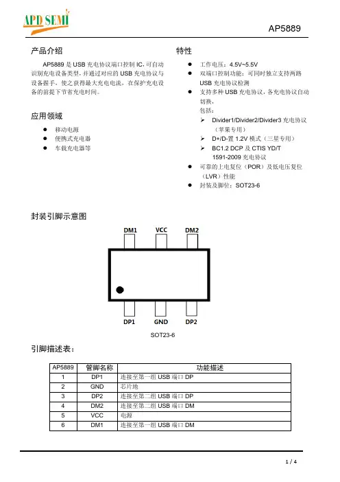
封装引脚示意图
SOT23-6
引脚描述表:
AP5889
应用电路:
双路2.4A配置应用电路内部框图:
内部模块框图
极限参数
:
电气特性:
(以下若无特别说明时:VCC=5V ,T A =25℃,输出无负载)
注*:LVR 复位模式时,USB 充电协议端口控制功能被关闭功能描述:
支持的USB 协议: 注:苹果设备的DividerX 模式向下兼容DividerX-1模式,即选择Divider3时,既支持最大功率12W 的Divider3苹果设备,也支持最大功率为10W/5W 的Divider2/1苹果设备。
封装形式
SOT23-6L。
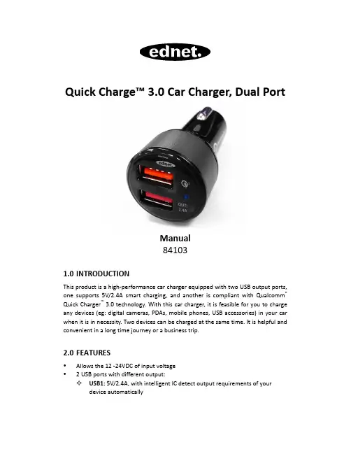
Quick Charge™ 3.0 Car Charger, Dual PortManual841031.0 INTRODUCTIONThis product is a high-performance car charger equipped with two USB output ports, one supports 5V/2.4A smart charging, and another is compliant with Qualcomm ® Quick Charger ™ 3.0 technology. With this car charger, it is feasible for you to charge any devices (eg: digital cameras, PDAs, mobile phones, USB accessories) in your car when it is in necessity. Two devices can be charged at the same time. It is helpful and convenient in a long time journey or a business trip.2.0 FEATURES•Allows the 12 -24VDC of input voltage • 2 USB ports with different output:✧ USB1: 5V/2.4A, with intelligent IC detect output requirements of your device automatically✧USB2: Intelligent integrated circuit equipped measures output andautomatically adjusts power outputs of 3~6.5V/3A, 6.5~9V/2A, and9~12V/1.5A for charging fast and safety.•Compliant with Qualcomm Quick Charge 3.0, charging speed is four times faster than normal charger.•Accurate limited current output and over current protection.•Over load protection and short circuit protection.•Over temperature protection with auto-recovery.•Select precision electrical components, fire lane version, and imported file-resistant plastic materials.•Light, smart and convenient to use.3.0SPECIFICATIONSInput/OutputInput 12~24V DCInput Plug Cigarette LighterOutput USB1(Smart):5V DC2.4AUSB2 (QC 3.0): 3~6.5V/3A, 6.5~9V/2A,9~12V/1.5AOutput Port 2USB A/FPerformanceRipple And Noise ≤200mVEfficiency ≥80%ProtectionOver Current Protection YesOverload Protection YesShort Circuit Protection YesOver Temperature Protection YesMechanicalColor White/BlackSize 30.1x68.3mmWeight 29.38gEnvironmentOperating Temperature Range0~30°CStorage Temperature Range -20~60°COperating Relative Humidity 30~90%RH.Storage Relative Humidity 10~90%RH.Certification CE,FCCOtherMTBF 50000HoursNOTE:1)More than 98% electronic products on the market can be charged via USB12)Charging speed is four times faster than the normal when charged via USB24.0PACKAGE CONTENTSBefore attempting to use this unit, please check the packaging and make sure the following items are contained in the shipping carton:•Main unit × 1•User Manual × 15.0CONNETION DIAGRAM6.0OPERATIONOperation Procedure1.Plug the USB car charger into the car cigarette lighter, and LED light turns blue.2.Plug the USB connector of the USB cable into the car charger's output interface,then plug the other end of the USB cable into the electronic devises (such as mobile phone, MP3, camera series).3.Please pull the car charger out after the electronic devises are fully charged.Operation Notes1.Please plug the car charger after starting the car.2.Please pull the car charger out after use or car flameout.Note: Our products have protection functions, and the two tips above are suggestions just for safety.3.Do not use the car charger with electronic products which own over-chargingspecifications, so as to avoid any problems caused by specification mismatching.4.Car charger will be a little overheated in the use process, and it's a normalphenomenon under the normal room temperature of less than 65 degree Celsius.5.When the car charger stops working under over-current, over-temperature orshort-circuit protection, please unplug the device after it automatically returns to work. Please check whether the device is compatible with this charger.6.Do not place or storage the car charger close to fire, such as stove, candles etc.7.Do not place or storage the car charger soak into liquid, such as swimming pool,bathtub, etc.8.Do not wash the car charger with corrosive cleaner.9.If the car charger cannot work properly, please contact the store or distributor inyour area.Hereby ASSMANN Electronic GmbH, declares that this device is in compliance with the requirements of Directive 2014/30/EU and the Directive 2011/65/EU for RoHS compliance. The complete declaration of conformity can be requested by post under the below mentioned manufacturer address.Warning:This device is a class B product. This equipment may cause some radio interference in living environment. In this case, the user can be requested to undertake appropriate measures to prevent interference.Assmann Electronic GmbHAuf dem Schüffel 358513 LüdenscheidGermany。
NPB-750 series■■■■‧‧ ‧ ‧‧ ‧‧ ‧‧‧‧ ‧‧ ‧‧ ‧ ‧ ℃ ℃ ‧ ‧‧‧ ‧ ‧ ‧DC output sideAC input sideBS EN/EN60335-1/2-29IEC60335-1/2-29UL62368-1TPTC004IEC62368-1NPB-750 seriesThis series provides 2 or 3 stage charging curveOFF: 3 stage(Default), ON: 2 stageCharging curve adjustable1.1 2 or 3-stage selectable via DIP S.W on panelCN714 built-in charging curves adjustable via DIP S.WDescription10 pins (HRS DF11-10DS)(NPB-750) pin assigment:NPB-7503. Auto Ranging for Charging (Default non-Auto ranging)a. NPB-750 has built-in auto ranging mode.(Note this mode is set to OFF by factory default and is suitable for lithium batteries with BMS only)b. When operating in auto ranging mode , NPB-750 will automatically detect the voltage of battery that is connected and adjustcharging voltage accordingly. It will not start charging unit appropriate battery voltage is detected.c. While under auto ranging mode, NPB-750's built-in MCU will adjust charging voltage. There is no potentiometer for voltageadjustment on the front panel.d. While under auto ranging mode, the charging current can be adjusted between 50~100%.(The charging current can not be adjusted via potentiometer while not operating in auto ranging mode)(1) Default factory setting is OFF via DC output side DIP S.W, Follow steps A1~A6 below to enable the setting. (Battery Management System).(2) Auto ranging function should use together with Lithium batteries and BMS (3) Do not exceed the output voltage and current ranges as specified in the NPB-750 specifications (please refer to page 2). Auto Ranging function by DIP S.W Setting CN71(DC Output Side)(AC Input Side)Command Code 0x00000x0020CommandName OPERATION VOUT_SETCANBus commend listTemperature compensation function to prolong battery life for lead-acid batteries. Temperature compensation range is 0 ~ 40The battery temperature sensor comes along with the charger can be connected to the unit to allow temperature compensation of the charging voltage.If the sensor is not used, the charger works normally.9.Temperature compensation(3 stage only)Between Remote ON-OFF (pin 7) and +12Vaux (pin 8)The NPB-750 can be turned ON/OFF by using the "Remote Control" function.S.W Short (pin 7 = 10.8 ~ 13.2V) S.W Open pin 7 = (-0.5 ~ 0.5V)8.Remote ON-OFF ControlPIN 14 LED Green Orange Orange (Flashing)RedFloat (stage 3) or Battery full Charging (stage 1 or stage 2)Auto ranging for chargingAbnormal status (OTP, OVP, Short circuit, Reverse polarity, Charging timeout.)Description10. DC Output Side LED Indicators & Corresponding Signal at Function PinsNTC sensor wire Remote control mating wire Connection Diagram。
电动汽车充电产品手册Electric car chargingProduct manual 杭州艾参崴电力科技有限公司专注于新能源技术服务,为客户提供从产品研发、技术输出、充电管理系统定制、方案设计、工程安装和设备维护等全面解决方案。
公司在电力行业有多年的技术服务经验和深厚的技术积累,公司坚持自主创新,先后开发了“交流充电桩监控板和通信模块、”“直流充电桩计量计费模块“、”充电桩测试仪和BMS模拟器“、“智能派接装置”等新技术、新产品。
公司通过ISO系列质量、环境、健康体系认证,通过德国TUV莱茵认证,是保时捷、宝马、奥迪、腾势、蔚来、现代、长安、北汽等多家新能源车企的充电服务商,在北京、上海、河北、江苏、陕西、四川、重庆、湖北、广东、福建等地均设有分公司或办事处,为新能源用户提供完善的服务。
企业愿景:致力于效能创新、累积组织资本、夯实创新基础、拥抱先进技术、铸造领先产品。
力争成为国内前十的新能源技术服务提供商! 企业价值观:开放自律、自存高远;求同存异、资源整合;洞察未来、立足市场;积极向上、坚韧正直! 艾参崴愿与股东、员工、客户、同行们立足当下、共赢未来!关于艾参崴ABOUT ICEWAY聚焦客户需求,提供有竞争力的新能源技术服务,持续为客户创造价值!⸺艾参崴电力科技迷你充电桩MINICHARGING PILE方寸小空间,运输方便可壁挂,可落地,易安装钢化玻璃面板美观又时尚动态液晶显示屏,极致视觉享受铝合金机身散热高效、耐磨损、耐老化、防腐蚀、防褪色最适合全天候户外使用金属质感,低调奢华有内涵模块化设计,稳定可靠待机功率低至3W,节能低耗充电过程智能化控制,安全高效应用场景:家庭车库、室外场所、整车配充等艾参崴迷你充电桩分为智能版、标准版、简易版三种规格。
具备(APP、微信、支付宝)扫码、刷卡启停、即插即充三种方式进行充电,通过2G/4G/以太网等方式实现通讯联网功能。
完善的充电监控功能和系统保护功能,让充电安全、高效又省心。
I T• D250SE è un caricabatterie CC/CC per un sistema a doppia batteria composto da una batteria di avviamento e una batteria di servizio.• D250SE ricarica la batteria di servizio tramite un alternatore o un pannello solare, oppure una combinazione di questi.• D250SE separa le batterie in un sistema a doppia batteria, pertanto sostituisce, ad esempio, un relè di separazione, VSR (Voltage Sensitive Relay), isolatore a diodo o un selettore di batteria meccanico.• D250SE può essere utilizzato da solo o in combinazione con SMARTPASS 120S. Usati in combin-azione, D250SE e SMARTPASS 120S sono in grado di effettuare la ricarica di fino a 140A.• L a batteria di avviamento è disponibile solo come batteria al piombo-acido.FUNZIONI:• R icarica della batteria di servizio da un alternatore convenzionale (tensione di carica costante)D250SE ricarica una batteria di servizio fino a 20A dalla batteria di avviamento quando è in funzione un alternatore convenzionale. Questa funzione viene disattivata quando il motore non è in funzione, per impedire che la batteria di avviamento si scarichi.• R icarica della batteria di servizio da un alternatore intelligente (con tensione di carica variabile)D250SE può ricaricare una batteria di servizio fino a 20A dalla batteria di avviamento quando è in funzione un alternatore intelligente. Questa funzione viene disattivata quando il motore non è in funzione, per impedire che la batteria di avviamento si scarichi. La sezione Installazione descrive come collegare il D250SE per attivare le funzioni Alternatore intelligente.• R icarica della batteria di servizio da un pannello solareD250SE può ricaricare ed effettuare la ricarica di mantenimento di una batteria di servizio da un pannello solare fino a 20A. D250SE impiega la MPPT (ricerca del punto di massima potenza) per massimizzare la potenza proveniente dal pannello solare.• S eparazione tra batteria di avviamento e batteria di servizioD250SE separa la batteria di avviamento dalla batteria di servizio quando il motore non è ac-ceso.• T ensione di carica con compensazione della temperaturaD250SE ottimizza la tensione di carica aumentandola in presenza di temperature inferiori a 25°C/77°F e riducendola in caso di temperature superiori a 25°C/77°F. La funzione è attiva solo nei programmi AGM e NORMALE.• R icarica di mantenimento della batteria di avviamento da un pannello solareD250SE effettua la ricarica di mantenimento della batteria di avviamento da un pannello solare a intervalli di 3 secondi se la batteria di servizio è completamente carica.• R icarica ottimizzata delle batterie AGMD250SE è in grado di erogare una tensione di carica adeguata per la ricarica ottimale delle batterie AGM (Absorbent Glass Mat, ossia microfibra di vetro assorbente), che richiedono una tensione di carica più elevata rispetto ad altri tipi di batteria al piombo-acido. La sezione Instal-lazione descrive come collegare il D250SE per attivare la funzione Batteria AGM.• C arica ottimizzata per batterie al litioIl caricabatterie D250SE può caricare al voltaggio appropriato le batterie al litio.• S MARTPASS 120S è una soluzione per fornire corrente di ricarica e gestire le utenze in un sistema a doppia batteria composto da una batteria di avviamento e una batteria di servizio.•S MARTPASS 120S separa le batterie in un sistema a doppia batteria, pertanto sostituisce, ad esempio, un relè di separazione, VSR (Voltage Sensitive Relay), isolatore a diodo o un selettore di batteria meccanico.• S MARTPASS 120S collega tra loro la batteria di avviamento e la batteria di servizio al fine di ricaricarle entrambe dall'alternatore.• S MARTPASS 120S protegge la batteria di servizio dalla scarica eccessiva, che danneggerebbe la bat-teria.• S MARTPASS 120S rifornisce le utenze dall'alternatore anziché dalla batteria di servizio mentre la batteria di servizio è in ricarica, il ché consente una ricarica più veloce.• S MARTPASS 120S può essere utilizzato da solo o in combinazione con il D250SE. Usati in com-binazione, D250SE e SMARTPASS 120S sono in grado di effettuare la ricarica di fino a 140A. FUNZIONI:• R icarica della batteria di servizio da un alternatore convenzionale (tensione di carica costante)SMARTPASS 120S ricarica una batteria di servizio fino a 120A dalla batteria di avviamento quando è in funzione un alternatore convenzionale. Questa funzione viene disattivata quando il motore non è in funzione, per impedire che la batteria di avviamento si scarichi.• R icarica della batteria di servizio da un alternatore intelligente (con tensione di carica variabile)SMARTPASS 120S può ricaricare una batteria di servizio fino a 120A dalla batteria di avvia-mento quando è in funzione un alternatore intelligente. Questa funzione viene disattivata quando il motore non è in funzione, per impedire che la batteria di avviamento si scarichi. La sezione Installazione descrive come collegare il SMARTPASS 120S per attivare le funzioni Alternatore intelligente.• P rotezione batteriaSMARTPASS 120S scollega le utenze quando la tensione della batteria di servizio è bassa, per evi-tare una scarica eccessiva, che danneggerebbe la batteria. Le utenze vengono ricollegate una volta che la tensione della batteria di servizio è aumentata. Collegare le utenze critiche direttamente alla batteria di servizio in modo che non vengano scollegate se la tensione scende al di sotto di 11,5V. • A vviamento assistitoSMARTPASS 120S collega automaticamente la batteria di servizio alla batteria di avviamento per 10 secondi, come ausilio qualora la batteria di avviamento non fosse in grado autonomamentedi mettere in moto il motore. Dopo aver attivato la funzione di avviamento assistito, SMARTPASS 120S visualizzerà un'indicazione di anomalia fino al raggiungimento dell'avviamento senza ricorso alla funzione di avviamento assistito.• S eparazione tra batteria di avviamento e batteria di servizioSMARTPASS 120S separa la batteria di avviamento dalla batteria di servizio quando il motore non è acceso.• A ssegnazione delle priorità della fonte di correnteSMARTPASS 120S è in grado di rilevare quando l'alternatore è in funzione e in tal caso alimenta le utenze con la corrente proveniente dalla batteria di avviamento, per interagire con D250SE e massimiz-zare l'efficienza di ricarica. Altrimenti le utenze vengono alimentate a corrente dalla batteria di servizio.60 • ITI TI T1. PANNELLO SOLARE ESEMPI DI INSTALLAZIONEPREREQUISITIPannello solare in grado di caricare una batte-ria di servizio da 40–300Ah. D250SE impiega la MPPT (ricerca del punto di massima potenza) per massimizzare la potenza proveniente da un pannello solare.SUGGERIMENTO 1Non collegare due pannelli solari in serie.Tensione max in ingresso 23V.PREREQUISITIUn sistema a doppia batteria, in cui il D250SEricarica una batteria di servizio da 40–300Ah apartire da un alternatore che effettua la ricaricaanche di una batteria di avviamento.Questo tipo di installazione risulta vantaggiosoquando:• L'alternatore non è in grado di erogare latensione di carica desiderata.SUGGERIMENTO 2Se l'alternatore è dotato di rilevamento esternodella tensione per la batteria di servizio, ilcablaggio di rilevamento della tensione deveessere collegato alla batteria di avviamento.SUGGERIMENTO 3Integrare il D250SE con unoSMARTPASS 120S se la capacità della batteriadi servizio è superiore a 100 Ah o se durantela carica è in corso un consumo parallelo. Ciòriduce il tempo di ricarica.2. Batteria di servizio piccola*Vedere “REQUISITI DI CAVI E FUSIBILI”*Vedere “REQUISITI DI CAVI E FUSIBILI”64 • IT IT • 65I TPREREQUISITIUn sistema a doppia batteria, in cui loSMARTPASS 120S ricarica una batteria di ser-vizio da 28–800Ah a partire da un alternatore che effettua la ricarica anche di una batteria di avviamento.Questo tipo di installazione risulta vantaggioso quando:• L'alternatore è in grado di erogare la tensione di carica desiderata.• La capacità della batteria di servizio è superi-ore a 100 Ah.• Le utenze vengono rifornite direttamente dall'alternatore contemporaneamenteall'esecuzione della ricarica della batteria di servizio.Vedere anche i suggerimenti 2 e 3.4. B atteria di servizio con utenze in parallelo*Vedere “REQUISITI DI CAVI E FUSIBILI”PREREQUISITIUn sistema a doppia batteria, in cui un D250SE in combinazione con uno SMARTPASS 120S ricarica una batteria di servizio da 100–800Ah. La corrente viene fornita da un pannello solare o da un alternatore. La batteria di avviamento viene caricata da un alternatore.Questo tipo di installazione risulta vantaggioso quando:• L'alternatore non è in grado di erogare la tensione di carica desiderata.• La capacità della batteria di servizio è superi-ore a 100 Ah.Durante la carica si verifica un consumo parallelo. Se si connettono i carichi (vedere le SPECIFICHE TECNICHE) alle uscite apposite dello SMARTPASS 120S, la batteria di servizio sarà in grado di ricaricarsi senza consumo parallelo e ai carichi applicati la corrente verrà fornita dall’alternatore.• La batteria di servizio dovrà essere protetta contro la scarica eccessiva. Collegare le utenze non critiche all'uscita utenze sullo SMARTPASS 120S. Collegare le utenze critiche direttamente alla batteria di servizio. SMARTPASS 120S in questo caso non disat-tiva le utenze critiche quando la batteria di servizio è completamente scarica. SUGGERIMENTO 4Collegare il cablaggio proveniente dalla batte-ria di avviamento e dalla batteria di servizio allo SMARTPASS 120S e non al D250SE. Vedere anche i suggerimenti 1, 2 e 3.PREREQUISITIUn sistema a doppia batteria, in cui è presenteun caricabatterie a 230/110V e un D250SEche, in combinazione con uno SMARTPASS120S, ricaricano una batteria di servizio conuna capacità di 150–800Ah.La corrente viene fornita alla batteria di servizio daun pannello solare e/o da un alternatore. La batte-ria di avviamento viene caricata da un alternatore.Questo tipo di installazione risulta vantaggiosoquando:• La carica dall'alternatore mentre sta ef-fettuando la ricarica (motore acceso) non èsufficiente, pertanto deve essere integrata adopera di un caricabatterie a 230/110V.• L'alternatore non è in grado di erogare latensione di carica desiderata.• La capacità della batteria di servizio è superi-• Durante la ricarica ha luogo un consumoparallelo. Se si connettono i carichi (vedere leSPECIFICHE TECNICHE) alle uscite appositedello SMARTPASS 120S, la batteria di serviziosarà in grado di ricaricarsi senza consumoparallelo e ai carichi applicati la corrente verràfornita dall’alternatore.SUGGERIMENTO 5Collegare un caricabatterie a 230/110V allabatteria di avviamento se questa necessita diricarica. In tal caso sia la batteria di avviamentoche la batteria di servizio verranno ricaricate inmodo ottimale dal caricabatterie a 230/110V.SUGGERIMENTO 6I carichi con elevato consumo di corrente(vedere le SPECIFICHE TECNICHE) devonoessere connessi direttamente alla batteria diservizio o di avviamento.5. Batteria di servizio grande con utenze in parallelo6. Collegare un caricabatterie CA/CC*Vedere“REQUISITIDICAVIEFUSIBILI”*Vedere“REQUISITIDICAVIEFUSIBILI”66 • ITI TFASE 1 DESULPHATION (DESOLFATAZIONE)Rileva le batterie solfatate. Gli impulsi di corrente e tensione rimuovono i solfati dalle piastre in piombo della batteria ripristinandone la capacità.FASE 2 BULK (MASSIMA POTENZA)Ricarica con la corrente massima fino all'80% circa della capacità della batteria.FASE 3 ABSORPTION (ASSORBIMENTO)Ricarica con corrente decrescente fino al 100% della capacità della batteria.FASE 4 FLOAT (FLOTTANTE)Mantiene la tensione della batteria al livello massimo con una tensione di ricarica costante. FASE 5 PULSE (IMPULSI)Mantiene la batteria al 95–100% della capacità. Il caricabatterie verifica la tensione della batteria e fornisce un impulso quando necessario per mantenerla completamente carica.PROGRAMMA DI CARICA D250SE PER BATTERIE AL PIOMBO-ACIDO IT • 67PROGRAMMA DI CARICA D250SE PER BATTERIE AL LITIOFASE 1 ACCETTAZIONEVerifica se la batteria è in grado di accettare la carica. Questa fase evita che la carica venga effettuata con un batteria difettosa.FASE 2 MASSARicarica con la corrente massima fino all'90% della capacità della batteria.FASE 3 ASSORBIMENTORicarica con corrente decrescente fino al 95% della capacità della batteria.FASE 4 FLOTTANTEMantiene la tensione della batteria al livello massimo con una tensione di carica costante. FASE 5 IMPULSOMantiene la batteria al 95–100% della capacità. Il caricabatterie verifica la tensione della batteria e fornisce un impulso quando necessario per mantenerla completamente carica.68 • IT*) La qualità della tensione di carica e della corrente di carica è molto importante. Un valore elevatodi oscillazione della corrente comporta il surriscaldamento della batteria e provoca l'invecchiamentoprematuro dell'elettrodo positivo. Un valore elevato di oscillazione della tensione può danneggiarealtri dispositivi collegati alla batteria. I caricabatterie CTEK forniscono tensione e corrente di ottimaqualità con valori di oscillazione ridotti.**) MPPT (ricerca del punto di massima potenza) trova la combinazione ideale di corrente etensione per massimizzare la potenza erogata.GARANZIA LIMITATACTEK conferisce la presente garanzia limitata all'acquirente originale del prodotto. La presentegaranzia limitata non è trasferibile. La garanzia è valida per difetti di fabbricazione o del mate-riale. Il cliente deve restituire il prodotto con la ricevuta di acquisto al punto di acquisto. Qualorail prodotto venga aperto, manomesso o riparato da soggetti diversi da CTEK o relativi rappresen-tanti autorizzati, la garanzia verrà invalidata. Uno dei fori per le viti nel lato inferiore del prodottopotrebbe essere sigillato. La rimozione o la manomissione del sigillo invaliderà la garanzia.CTEK non fornisce altre garanzie oltre alla presente garanzia limitata e non potrà essere ritenutaresponsabile per eventuali costi diversi da quelli sopra indicati né danni consequenziali. Inoltre,CTEK non è vincolata ad altre garanzie oltre alla presente garanzia.ASSISTENZAVisitare: www.ctek.it per assistenza, le domande più comuni, il manuale di istruzioni più aggior-nato e ulteriori informazioni sui prodotti CTEK. IT • 71。
EV CHARGER CONNECTOREV HIGH-PERFORMANCE CONNECTOREV充电接口EV高性能连接器RENHOTEC GROUPcontents目录GB标准交直流充电接口GB standards AC and DC charging connector 04~22 IEC标准交流充电接口IEC standards AC charging connector 23~30 SAE标准交流充电接口SAE standards AC charging connector 31~34 企标交流充电接口Enterprise standards AC charging connector 35~40 充电模式2Charging mode 2 41~50 充电模式3Charging mode 3 51~60 电锁Electromagnetic lock 61~66插头固定座Plug dummy socket67~67二$已巨[己》,'-1-_EV Conductive ChargingConnection Device Option GuideEV传导充电连接装置选型引导囚电源相数(省略痴渔相)Power phase (omit means single phase)产品类别(S插座P插头)Product classification (S Socket, P Plug)额定电流Rated current电锁(省略表示无配置)Electromagnetic lock (omit means no configuration)翻盖(省略表示无配置)Flip (omit means no configuration)参照标准(见表1)Reference standard (see Table 1)公司简写Company profile使用场所(Z供电C车辆)Use place (Z means charging pile, C means electric vehicles)产品版本(省略代表第—版)Product version (omit means the first version)Ev Conductive ChargingConnection Device Reference StandardsEV传导充电用连接装置参照标准(表1)编号/Seria l No. 参照标准/Reference standards《电动汽车传导充电用连接装置》《EV conductive charging connection d的ce》20234.2-2015《电动汽车传导充电用连接装置》《EV conductive charging connection d的ce》20234.3-2015SAE Jl 772-2010IEC2a+- IEC2b 62196-2 IEC 2010标准表格(standards table)2-lla 62196-2 IEC 2010标准表格(standards table)2-llbIEC2e| IEC2f 62196-2 IEC 2010标准表格(standards table)2-lle 62196-2 IEC 2010标准表格(standards table)2-llfNV X x RHT xxx G ELRHTRHTAC CHARGING PLUG交流充电插头产品应用:充电桩端电连接输入Product application: Charging pile electrical connection型号Model:e NV2Z-R H T-EV10Pe NV2Z-R H T-EV16Pe NV2Z-R H T-EV32P匡日-I产品特点Featu res·符合GB/T20234.2-2015规定及要求Meet G B/T 20234.2-2015 regulations and requirements·外形美观,手持式设计符合人体工程学原理,插拔便捷Nice appearance, hand-held ergonomic design, eas-j plug机械性能Mechanical properties·机城寿命:空载拔插>10000次Mechanical life: no-load plug in/pull out> 10000 times·抗冲击力:可承受1米禹度跌落与2吨车辆罹压力·插针头部采用安全绝缘设计,防止人手意外直接接触Safety pins insulated head design to prevent accidental diirecrtcontactwith staff.优越防护性能,防护等级达到IPSS(工作状态)Excellent protection performance,protection grade IPSS(workingcondition)电气性能Electrical Performance·额定工作电流:lOA、16A或32ARated current: lOA、16Aor32AIm p at of external force: can afford lm drop and 2tvehicle run over pressure ·工作电压:250V或440V环境性能Environmental performance·工作环境温度:-30°c--+so0cOperating temperature: -30°C--+so0c材料应用Applied Materials·外壳材料:热塑性塑料,阻燃等级UL94V-OCase Material: Thermoplastic,flame retardant grade UL94 V-0·插针:铜合金,表面镜银+顶部热塑性塑料Pin: Copper alloy,silver + thermoplastic on the topOperation voltage: 25CN or 440V·绝缘电阻:>lOOOMO (DC500V)Insulation resistance: >lOOOMO(DCSOCN)·端子温升:<SOKTerminal temperature rise: <SOK·耐压:200CNWithstand V oltage: 200CN.接触阻抗:O.SmO MaxContact R esistance: O.SmO Max产品选型与标准配线Model selection and the standard wiring型号/Model额定电流/Ratedcurrent 线缆规格/Cable specificationNV2Z-R H T-EV10P lOA 3X2.Smm2+ 2X 0.75mm2NV2Z-R H T-EV16P 16A单相/Singlephase 3X2.Smm2+ 2X 0.7Smm2NV2Z-R H T-EV16P 16A三相/Three phase SX2.Smm红2X0.7Smm2NV2Z-R H T-EV32P 32A屿/Singlephase 3X6mm2+2X0.75mm2NV2Z-R H T-EV32P 32A三相/Three phase 5X6mm2+2X0.75mm2AC CHARGING PLUG 交流充电插头产品应用:电动汽车端电连接输入Product application: Electric vehicle electrical connection型号M odel:e NV2C-R H T-EV10P e NV2C -R H T-EV16P e NV2C-R H T-EV32P,J_|产品特点Featu res·符合GB/T20234.2-2015规定及要求Meet GB/T 20234.2-2015 regulations and requirements ·外形美观,手持式设计符合人体工程学原理,插拔便捷N ice a ppearance, hand-held ergonomic design, ea羽plug机械性能Mechanical properties·机械寿命:空载拔插>10000次Mechanical life : no-load plug in/pull out> 10000 times ·抗冲击力:可承受1米高度跌落与2吨车辆诵压力·插针头部采用安全绝缘设计,防止人手意外直接接触Safety pins insulated head design to prevent accidental diirecrt contact with staff.优越防护性能,防护等级达到IPSS(工作状态)E xcellent protection performance,protection grade IPSS(working condition)电气性能Electrical Performance·额定工作电流:lOA 、16A 或32ARated current : lOA 、16Aor32A lmpatof external fo rce: can afford lm drop and 2t vechicle run o ver pressure •工作电压:巧W 或440V环境性能Environmental performance ·工作环境温度:-30°C 叶50°C Operating temperature: -30'C 叶50°C材料应用Applied Materials·外壳材料:热塑性塑料,阻燃等级UL94V -OCase Material: Thermoplastic,flame retardant grade U L94 V -0 ·插针:铜合金,表面锦银+顶部热塑性塑料Pin: Copper alloy,silver+ thermoplastic on the topOperation voltage: 250V or 44W ·绝缘电阻:>lOOOMO (D CSOW)Insulation resistance: > l OOOMO(DCSO冈·端子温升:<SOKTerminal temperature rise : <SOK .耐压:2000VWithstand V oltage: 20叨V ·接触阻抗:0.5m0Max Contact R esistance: 0.5m0 Max产品选型与标准配线Model selection and the standard wiring型号/Mo del 额定电流/Ratedcurrent 线缆规格/Cable specification NV2C-R H T-EV10P lOA3X2.5mm 2+ 2X0.75mm 2 NV2C-R H T-EV16P 16A单相/Single phase 3X2.Smm 2 + 2X0.75mm 2 一lNV2C-R H T-EV16P 16A三相/Three phase SX2.Smm 2 + 2X0.7Smm 2 lNV2C-R H T-EV32P 32A单相/Single phase 3 X 6mm 2 + 2X 0.75mm 2 NV2C-R H T-EV32P32A三相/Three phase5 X 6mm 2 + 2 X 0.75mm 2致力于成为全球电动汽车连接技术的领导者Dedicated T o Becoming Global Electric Vehicle Leader In Connection Technolo窃AC CHARGING PLUG 交流充电插头产品应用:充电桩端电连接输入Product application: Charging pile electrical connectionlll型号Model:e e e NV3Z-R H T-EV10P NV3Z-R H T-EV16P NV3Z-R H T-EV32P_I 产品特卢Fe ature s·符合GB/T 20234.2-2015规定及要求MeetGB/T 20234.2-2015 regulations and requirements ·外形美观,手持式设计符合人体工程学原理,插拔便捷Nice appearance, hand-held ergonomic design, easy plug机械性能Mec h anica l properties·机械寿命:空载拔插>10000次Mechanical life: no-load plug in/pull out> 10000 times·抗冲击力:可承受1米高度跌落与2吨车辆瑕压力Im p at of external force: can afford lm drop and 2t vechicle run over pressure环境性能Environmental perf ormance ·工作环境温度:-30'C ~+50°COperating temperature: -30'C-+50°C材料应用Applied Materials ·外壳材耜:热塑性塑料,阻燃等级UL94V-O Case Material: Thermoplastic,flame retardant grade UL94 V-0·插针:铜合金,表面锦银+顶部热塑性塑料Pin: Copper alloy,silver + thermoplastic on the top产品选型与标准配线Mode l selection and the standard wiring·插针头部采用安全绝缘设计,防止人手意外直接接触Safety pins insulated head d esign to prevent accidental diirecrt contactwith staff·优越防护性能,防护等级达到I PSS(工作状态)Excellent protection performance,protection grade IPSS w orking condition)电气性能Electrical Performance·额定工作电流:lOA、16A或32A Rated current : lOA 、16Aor 32A·工作电压:250V或440V Operation voltage: 250V or 440V ·绝缘电阻:>lOOOMO (DCSOOV)Insulation resistance: > l OOOMO(D CSOOV)·端子温升:<SOK Terminal temperature rise: <SOK·耐压:2000VWithstand Volrage : 2000V ·接触阻抗:O.SmOMaxContact Resis扫nce:O.SmO M ax型号/Model额定电流/Rated current 线缆规格/Cable specification Nl/3Z-R H T-EV10PlOA3X2.Smm 2+ 2X 0.7Smm 2 16A单相/Single phase 3X2.Smm红2X0.7Smm 2NV3Z-R H T-EV16P 16A三相/Three phase 5X 2.Smm 2 + 2 X O 75mm 2 NV3Z-R H T-EV32P32A单相/Single phase3X6mm 2+2X0.75mm 2AC CHARGING SOCKET 交流充电插座产品应用:充电桩端电连接输入Product application: Charging pile electrical connection产品特点Features·符合GB/T20234.2-2015规定及要求Meet GB/T20234.2-2015 regulations and requirements ·外形美观,上翻盖防护,支持后安装方式Nice appearance, up flip protection,support back i nstallation机械性能Mec h anica l properties ·机械寿命:空载拨插>10000次Mec hanical life :no-load plug in/pull out> 10000 times ·耦合时插拨力:>4SN<80N Coupled insertion force: >4SN<80N环境性能Environmental performance ·工作环境温度:-30'C-+50°C 0 p erati n g tern p eratu r e: -30'C-+50°C 材料应用App l ied Mater i a l s ·外壳材料:热塑性塑料,阻燃等级UL94V-OCase Material: Thermoplastic,flame retardant grade UL94 V-0·插套:铜合金,表面镜银Contact bush: Copper alloy,silver plating产品选型与标准配线M o d e l selection and the standard wiring型号Model:e NV3Z-R H T-GEL-EV16S e NV3Z-R H T-GEL-EV32S_·可靠性材料,阻燃、耐压、耐磨耐冲击、高抗油Reliability of materials, a ntiflaming, pressure-resistant, abrasion resistance, impact resistance and high o il .优越防护性能,防护等级达到IPSS(工作状态)Excellent protection performance,protection grade IPSS(working condition)电气性能E l ectrica l Performance .额定工作电流:16A或32A Rated current : 16A or 32A ·工作电压:250V或440V Operation voltage: 250V o r 440V ·绝缘电阻:>lOOOM O (DCSOOV)Insulation resistance: > l OOOMO(DCSOOV)·端子温升:<SOK Terminal temperature rise: <SOK ·耐压:2000VWithstand Voltage: 2000V .接触阻抗:05m 0Max Contact Resistance: O.SmO Max额定电夼/Rated current 线缆规格/Cable specification 16A单相/Single phase 3X2 S mm 2+2X0.75mm 2 型号/Mo delNV3Z-R H T-G EL-EV16S16A三相/Three phase 5X2.Smm 2+ 2X 0.75mm 2 32A单相/Singlephase 3X 6mm 2 + 2 X 0.75mm 2 NV3Z-R H T-GEL-EV32532A三相/Three phase5X 6mm 2 + 2 X 0.75mm 2致力于成为全球电动汽车连接技术的领导者Dedicated To Becoming G lobal Electric Vehicle Leader In Connection Technolo窃AC CHARGING PLUG 交流充电插头产品应用:电动汽车端电连接输入Product application: Electric vehicle electrical connection型号Model:e NV3C-R H T-EV10P e NV3C-R H T-EV16P e NV3C-R H T-EV32P_|产品特点Fe ature s·符合GB/T20234.2-2015规定及要求Meet G B/T20234.2-2015 regulations and requirements ·外形美观,手持式设计符合人体工程学原理,插拔便捷Nice appear ance, hand-held ergonomic design, easy plug机械性能Mechanical properties ·机械寿命:空载拨插>10000次Mechanical life : no-load plug in/pull out> 10000 times ·抗冲击力:可承受1米高度跌落与2吨车辆诵压力·插针头部采用安全绝缘设计,防止人手意外直接接触Safety pins insulated headdesign to prevent accidental diirecrtcontact with staff·优越防护性能,防护等级达到I PSS(工作状态)Excellent protection performance,protection grade IPSS(working condition)电气性能Electrical Performance ·额定工作电流:lOA 、16A或32A Rated current : lOA、16Aor 32A Im p at of external force: can afford lm drop and 2t vehicle run over pressure •工作电庄:250V或440V 环境性能Environmental performance·工作环境温度:-30'C ~+50°C Operating temperature: -30'C ~+50°C 材料应用Applied Materials ·外壳材料:热塑性塑料,阻燃等级UL94V -OOperation voltage: 250V or 440V .绝缘电阻:>lOOOMO (DCSOOV) Insulation resistance: >lOOOMO(DCSOOV) ·端子温升:<SOKTerminal temperature rise : <SOK .闭压:2000VCase Material: Thermoplastic,flame retardant grade UL94 V-0·插针:铜合金,表面镜银+顶部热塑性塑料Withstand Voltage : 2000V .接触阻抗:O.SmOMax Contact Resistance: O.SmO MaxPin: Copper alloy,silver + thermoplastic on the top产品选型与标准配线Mode l selection and the standard wiring型号/Model L额定电流/Rated current 线缆规格/Cable specification NV3C-R H T-巳/lOP 3X2.5mm 2lOA16A单相/Single phase 3 X 2.5mm 2 + 2 X 0.75mm 2 NV艾-R H T-EV16P 尸一16A三相/Three phase 5 X 2.5mm 2 + 2 X 0.75mm 2 Nl/3C-R H T-巳32P32A单相/Single phase3X6mm 2+ 2X0.75mm 2AC CHARGING SOCKET交流充电插座产品应用:电动汽车端电连接输入Product application: Electric vehicle electrical connection产品特点Features·符合GB/T20234.2-2015规定及要求Meet GB/T20234.2-2015 regulations and requirements·外形美观,护盖可左右安装,支持前安装方式Nice appearance, flip can left and right installation,supportfrontinstallation机械性能Mec h an i ca l properties·机械寿命:空载拔插>10000次Mechanical life: no-load plug in/pull out> 10000 times·耦合时插拔力:>4SN<80NCoupled insertion force: >45N<80N环境性能Environmental performance·工作环境温度:-30'C-+50°COperating temperature: -30'C-+50°C材料应用Applied Materials·外壳材料:热塑性塑料,阻燃等级UL94V-OCase Material: Thermoplastic,flame retardant grade U L94 V -0·插套:铜合金,表面锦银Contact bush: Copper alloy,silver p lating产品选型与标准配线Model se l ection and the standard wiring型号Model:e NV3C-R H T-G-EV16Se NV3C-R H T-G-EV32Se NV3C-R H T-G-EV63S_·可靠性材料,阻燃,耐压、耐磨、耐冲击、高抗油Reliability of materials, antiflaming, pressure-resistant, abrasionresistance, impact resistance and h igh o仆·优越防护性能,防护等级达到I PSS(工作状态)Excellent protection performance,protection grade IPSS(workingcondition)电气性能Electrical Performance·额定工作电流:16A或32A或63ARated current : 16A or 32A or 63A·工作电压:250V或440VOperation v oltage: 250V or 440V·绝缘电阻:>lOOOMO(DCSOOV)Insulation resistance: > l OOOMO(DCSOOV)·端子温升:<SOKTerminal temperature rise: <SOK·耐压:2000VWithstand V oltage: 2000V.接触阻抗:O.SmOMaxContact Resistance: O.SmO Max型号/Model| 额定电流/Rated current 线缆规格/Cable specification16A单相/Single phase 3X2.Smm2+ 2X0.75mm2 NV3C-R H T-G-EV16S16A三相/Three phase SX2.Smm2 +2X0.75mm232A单相/Single phase 3 X6mm2+ 2X 0.75mm2 Nl/3C-R H T-G-El/32S32A三相/Three phase 5 X6mm2+ 2X 0.75mm2 NV3C-R H T-G-EV63S 63A三相/Three phase SX16mm2 +致力于成为全球电动汽车连接技术的领导者Dedicated To Becoming G lobal Electric Vehicle Leader In Connection Technolo窃AC CHARGING PLUG 交流充电插头产品应用:充电桩端电连接输入Product application: Charging pile electrical connectione e 型号Model:NV4Z-R H T-EV32P NV4Z-R H T-EV63P_I 产品恃卢Fe ature s·符合G B /T 20234.2-2015规定及要求Meet GB/T 20234.2-2015 regulations and requirements ·外形美观,手持式设计符合人体工程学原理,插拔便捷Nice appearance, hand-held ergonomic design, easy plug机械性能Mechanical properties·机械寿命:空载拔插>10000次Mechanical life : no-load plug in/pull out> 10000 times·抗冲击力:可承受1米高度跌落与2吨车辆瑕压力·插针头部采用安全绝缘设计,防止人手意外直接接触Safety pins insulated head design to prevent accidental diirecrt contactwith staff.优越防护性能,防护等级达到I PSS(工作状态)Excellent protect ion performance,protection grade IPSS(working condition)电气性能Elect rical Performance·额定工作电流:32A或63A Rated current : 32A o r63AIm p at of external force: can afford lm d rop and 2t vehicle run over p ressure •工作电压25(JV或440V环境性能Environmental performance ·工作环境温度:-30'C ~+50°C Operating temperature: -30'C ~+50°C材料应用Applied Materials ·外壳材料:热塑性塑料,阻燃等级UL94V-OCase Material: Thermoplastic,flame retardant grade UL94 V-0·插针:铜合金,表面镜银+顶部热塑性塑料Pin: Copper alloy,silver + thermoplastic on the top产品选型与标准配线Mode l selection and the standard wiringOperation voltage: 250V or 440V·绝缘电阻:>lOOOMO (DCSOOV) Insulation r esistance: > l OOOMO(DCSOOV) ·端子温升:<SOK Terminal temperature rise : <SOK.耐压:2000VWithstand Voltage : 2000V·接触阻抗:O.SmOMaxCon坊ct Resistance: O.SmO Max竺号/ModelNV4Z-R H T-EV32P NV4Z-R H T-EV63P额定电流/Rated current 3扒三相/Three phase63A三相/Three phase 二线缆规格/Cable specification 5 X 6mm 2 + 2 X 0.75mm 2SX 16mm 2+ 5 X 0.75mm 2AC CHARGING SOCKET交流充电插座产品应用:充电桩端电连接输入Product application: Charging pile electrical connection型号 Model:e NV4Z-R H T-G-EV16Se NV4Z-R H T-G-EV32Se NV4Z-R H T-G-EV 63S_ I产品特点Featu res·符合GB/T20234.2-2015规定及要求Meet GB/T20234.2-2015 regulations and requirements·外形美观,上翻盖防护,支持前安装方式·可靠性材料,阻燃,耐压、耐磨、耐冲击、高抗油Reliability of materials, antiflaming, pressure-resistant, abrasionresistance, impact resistance and high oilNice appearance, up f lip protection,support front installation.优越防护性能,防护等级达到IPSS(工作状态)机械性能Mechanical properties·机械寿命:空载拨插>10000次Mechanical life: no-load p lug i n/pull out> l OOOOtimes·耦合时插拔力:>4SN<80NCoupled insertion force: >4SN<80N环境性能Environmental performance·工作环境温度:-30'C-+50°COperating temperature: -30'C-+50'C材料应用Applied Materials·外壳材料:热塑性塑料,阻燃等级UL94V-OExcellent protection performance,protection grade IPSS(workingcondition)电气性能E l ectrica l Performance·额定工作电流:16A或32A或63ARated current : 16A or 32A or 63A·工作电压:250V或440VOperation voltage: 250V or 440V·绝缘电阻:>lOOOMO (DCSOOV)Insulation r esistance: > l OOOMO(DCSOOV)·端子温升:<SOKTerminal t emperature rise: <SOK·耐压:2000VCase Material: Thermoplastic,f lame retardant grade UL94 V-0·插套:铜合金,表面镜银Withstand Voltage: 2000V·接触阻抗:05m0MaxContact Resistance: O.SmO MaxContact bush: Copper alloy,silver plating产品选型与标准配线Mode l selection and the standard wiring型号/ModelNV4Z-R H T-(j-fV16SNV4Z-R H T-(j-fV32SNV4Z-R H T-(j-fV63S额定电流/Rated current16A16A三相/Three phase32A单相/Single phase32A三相/Three phase63A三相/Three_p_hase线缆规格/Cable specification3X2.Smm2+ 2X0.75mm2SX2.Smm2+ 2X0.7Smm23X6mm2+2X0.75mm2SX6mm2+2X0.75mm 2SXl面子12+ 2 X0.7Smm2致力于成为全球电动汽车连接技术的领导者Dedicated To Becoming G lobal Electric Vehicle Leader In Connection Technolo窃AC CHARGING PLUG 交流充电插头产品应用:电动汽车端电连接输入Product application: Electric vehicle connection型号M odel:e NV4C-R H T-EV32P e NV4C-R H T-EV63P.`_ I产品特卢F eatu res·符合G B /T 20234.2-2015规定及要求Meet G B/T 20234.2-2015 regulations and requirements ·外形美观,手持式设计符合人体工程学原理,插拔便捷Nice appearance, hand-held ergonomic design, ea羽plug机械性能Mec h a n ica l properties ·机械寿命:空载拔插>10000次Mechanical life : no-load plug in/pull out> 10000 times ·抗冲击力:可承受1米高度跌落与2吨车辆碌压力·插针头部采用安全绝缘设计,防止人手意外直接接触Safety pins insulated head design to prevent accidental diirecrt contactwith staff·优越防护性能,防护等级达到I P S S (工作状态)Excellent protection per formance,protection grade IPSS(workingcondition)电气性能E l ectrica l Performance .额定工作电流:32A或6扒Rated current : 32A or 63A Im p at of external force: can afford lm drop and 2t vehicle run over pressure ·工作电压:250V或440V 环境性能Environmental performance ·工作环境温度:-30'C ~+50°C Operating temperature: -30'C ~+50°C 材料应用Applied Materials .外壳材耜:热塑性塑料,阻燃等级UL94V -OCase Material: Thermoplastic,flame retardant grade UL94 V -0 .插针:铜合金,表面镜银+顶部热塑性塑料Pin: Copper alloy,silver + thermoplastic on the topOperation voltage: 250V or 440V .绝缘电阻:>lOOOMO (DCSOOV) Insulation resistance: >lOOOMO(DCSOOV) ·端子温升:<SOKTerminal temperature rise : <SOK ·耐压:200(JI/Withst a nd Voltage: 2000V ·接触阻抗:O.SmO Max Contact Resistance: O.SmO Max产品选型与标准配线Mode l selection and the standard wiring型号/Mode l NV4Z-R H T-8/32P NV4Z-R H T-8/63P额定电流/Rated current 32A三相/Three phase 63A三相/Three phase线缆规格/Cable specification 5 X 6mm 2 + 2 X 0.75mm 2 5 X 16mm 2 + 5 X 0.75mm 2AC CHARGING SOCKET 交流充电插座产品应用:电动汽车端电连接输入Product application: Electric vehicle electrical connection产品特点Features·符合GB/T20234.2-2015规定及要求Meet GB/T20234.2-2015 regulations and requirements ·外形美观,护盖可左右安装,支持前安装方式Nice appearance, flip can left and ri ght i nstallation,support front installation机械性能Mechanica l properties ·机械寿命:空载拨插>10000次Mechanical life : no-load plug i n/pull out> 10000 times ·耦合时插拔力:>4SN<80N Coupled insertion force: >4SN<80N环境性能Environmental performance·工作环境温度:-30'C-+50°C0 p erati n g tern p eratu r e: -30'C-+50°C 材料应用Applied Materials ·外壳材料:热塑性塑料,阻燃等级UL 94V-OCase M aterial: Thermoplastic,flame retardant grade UL94 V-0.插套:铜合金,表面镜银Contact bush: Copper alloy,silver plating产品选型与标准配线Mo d e l selection and the standard wiring型号Model:e NV4C-R H T-G-EV16S e NV4C-R H TG-EV32S e NV4C-R H T-G-EV63S_·可靠性材料,阻燃、耐压、耐磨、耐冲击、高抗油Reliabilit y of materials, a ntiflaming , p ressure-resistant, abrasion resistance , impact resistance and high oil .优越防护性能,防护等级达到IPSS(工作状态)Excellent protection performance,protection grade IPSS(working condition)电气性能E l ectrica l Performance ·额定工作电流:16A或32A或63A Rated current : 16A or 32A or 63A ·工作电压:250V或440V Operation voltage: 250V or 440V ·绝缘电阻:>1000M O (DCSOOV)Insulation resistance: > l OOOMO(DCSOOV)·端子温升:<SOKTerminal temperature rise: <SOK .耐压:2000VWithstand Voltage : 2000V .接触阻抗:05m0Max Contact Resistance: O.SmO Max型号/Model NV4C-R H T-G-EV16S NV4C-R H T-G-EV32S NV4C-R H T-G-EV63S额定电夼/Rated current16A线缆规格/Cable specification3 X 2.Smm 2 + 2 X 0.7Smm 2 SX2.Smm 2+ 2X0.7Smm 2 ..16A三相fT hr竺phase 32A单相/Single phase 32A三相[Three phase 6弘三相{Threephase 3 X 6mm 2 + 2X 0.75mm 25 X 6mm 2+ 2 X 0.75mm 25 X 16mm 2+ 2 X 0.7Smm 2致力于成为全球电动汽车连接技术的领导者Dedicated To Becoming G lobal Electric VehicleLeader In Connection Technolo窃AC CHARGING PLUG交流充电插头产品应用:充电桩端电连接输入Product application: Charging pile electrical connection型号Mo del: e VSZ-R H T-EV16Pe VSZ-R H T-EV32P^_ I产品特卢Features·符合GB/T20234.2-2015规定及要求Meet GB/T20234.2-2015 r egulations and requirements ·外形美观,手持式设计符合人体工程学原理,插拔便捷Nice appearance, hand-held ergonomic design,easy plug 机械性能Mechanical properties·机械寿命:空载拨插>10000次• 00头部采用安全绝织妇计,防止人手意外直接接触Safety pins insulated headdesign to prevent accidental diirecrt contact with staff·优越防护性能,防护等级达到IPSS(工作状态)Excellent protection perform ance,protection grade IPSS(working condition)电气性能Electrical PerformanceMechanical life: no-load plug in/pull out> lOOOOtimes•额定工作电流:16A或32A ·抗冲击力:可承受1米高度跌落与2吨车辆瑕压力Rated current :16Aor 32A Im p at of external force: can afford lm drop and 2t vehicle run over pressure •工作电压:250V环境性能Environmental performance·工作环境温度:-3o•c-+so0cOperating temperature:-30°c-+so0c材料应用Applied Materials·外壳材料:热塑性塑料,阻燃等级UL94V-OCase Material: T hermoplastic,flame retardant grade UL94 V-0 ·插针:铜合金,表面镜银+顶部热塑性塑料Pin: Copper alloy,silver + thermoplastic on the topOperation vol坊ge:2sov·绝缘电阻:>lOOOMO (DCSOOV) Insulation resis扫nee:>lOOOMO(DCSOOV)·端子温升:<SOKTerminal temperature rise :<SOK .耐压:2000VWithstand V oltage :2000V.接触阻抗:O.SmO MaxContact Resistance:O.SmO M ax产品选型与标准配线Mo d e l selection and the standard wiring 型号/Mo delVSZ-R H T-EV16P VSZ-R H T-EV32P 十额定电流/Rated current16A32A线缆规格/Cable specification3 X2.Smm2 + 2 X0.7Smm23X6mm2+ 2X0.7Smm2AC CHARGING PLUG 交流充电插头产品应用:电动汽车端电连接输入Product application: Electric vehicle electrical connection品特点Features·符合GB/T 20234.2-2015规定及要求Meet GB/T 20234.2-2015 regulations and requirements ·外形美观,手持式i缸十符合人体工程学原理,插拔便捷Nice a ppearance, hand-held ergonomic design, e asy plug机械性能Mechanical properties ·机械寿命:空载拨插>10000次Mechanical life: no-load plug in/pull out> l OOOOtimes ·抗冲击力:可承受1米高度跌落与2吨车辆瑕压力已lmpat of external force: can afford l m d rop and 2t vehicle run over pressure 环境性能Environmen t a I pe rforma n ee ·工作环境温度:-30°C-+50°C Operating temperature: -30°C -+50°C 材料应用Applied Materials ·外壳材料:热塑性塑料,阻燃等级UL94V-OCase M aterial: Thermoplastic,flame re口rdant grade U L 94 V -0 ·插针:铜合金,表面银银+顶部热塑性塑料Pin: Copper alloy,silver+ ther moplastic on the top产品选型与标准配线Mode l selection and the standard wiring型号 Model:e VSC-R H T-EV16P e VSC-R H T-EV32P_·插针头部采用安全绝缘设计,防止人手意外直接接触Safety pins insulated head d esign to prevent accidental diirecrt contact with staff·优越防护性能,防护等级达到IP 55(工作状态)Excellent protection performance,protection grade I P S S(working condition)电气性能Electr i ca l Performance ·额定工作电流:16A或32A Rated current : 16A or 32A ·工作电压:250V Operation voltage: 250V ·绝缘电阻:>lOOOMO (DCSOOV)Insulation resistance: > l OOOMO(DCSOOV)·端子温升:<SOKTerminal temperature rise : <SOK ·耐压:2000VWithstand Voltage : 2000V ·接触阻抗:O.SmOMax Contact Resistance: O.SmO Max型号/Model VSC-R H T-EV16P VSC-R H T-EV32P额定电流/Rated current 16A 线缆规格/Cable specification 3 X 2.Smm 2 + 2 X 0.75mm 2 32A3 X 6mm 2+ 2 X 0.75mm 2致力于成为全球电动汽车连接技术的领导者Dedicated To Becoming Global Electric V ehicleLeader In Connection T echnol ogyAC CHARGING PLUG交流充电插头产品应用:充电桩端电连接输入Product application: Charging pile electrical conn ect ion产品特点Features·符合GB/T20234.2-2015规定及要求MeetGB/T 20234.2-2015 regulations and requirements·外形美观,手持式设计符合人体工程学原理,插拔便捷Nice appearance, hand-held ergonomic design,easy plug机械性能M echanical properties·机械寿命:空载拔插>10000次Mechanical life: no-load plug in/pull out> 10000 times·抗冲击力:可承受1米高度跌落与2吨车辆瑕压力Im p at of external f orce:can afford lm drop and 2tvehicle run over pressure 环境性能Environmenta I performance·工作环境温度:-30°C-+50'COperating temperature:-30'C-+50'C材料应用Applied Mat erials·外壳材料:热塑性塑料,阻燃等级UL94V-OCase M aterial: T hermoplastic,flame retardant grade UL94 V-0·插针:铜合金,表面镜银+顶部热塑性塑料Pin: Copper alloy,silver + thermoplastic on the top产品选型与标准配线Mode l selection and the standard wiring型号Model:e NV6Z-R H T-EV16Pe NV6Z-R H T-EV32P_·插针头部采用安全绝缘设计,防止人手意外直接接触Safety pins insulated head design to p revent accidental diirecrt contact with staff.优越防护性能,防护等级达到IP66(工作状态)Excellent protection performance,protection grade IP66(working condition)电气性能Electrica I Performa n ee.额定工作电流:16A或32ARated current: 16Aor32A·工作电压:250VOperation voltage: 250V·绝缘电阻:>lOOOMO (DC500V)lnsu l ation resistance: > l OOOMO(DCSOOV).端子温升:<50kTerminal temperature rise: <SOK.耐压2000VWiths匕nd Vol也ge:2000V.接触阻抗:0.5m0MaxContact Resis扫nce:0.5m0 Max型号/Model额定电流/Rated current 线缆规格/Cable specification16A 3X2.5mm2 + 2X0.75mm2 NV6Z-R H T-EV16P16A三相/Threephase SX2.5mm2 + 2X0.75mm2 NV6Z-R H T-EV32P 32A单相/Single phase 3X6mm2+ 2X0.75mm2AC CHARGING PLUG交流充电插头产品应用:电动汽车端电连接输入Product application: Electric vehicle electrical connection产品特点Features·符合GB/T20234.2-2015规定及要求Meet GB/T20234.2-2015 regulations and requirements·外形美观,手待式设计符合人体工程学原理,插拔便捷Nice appearance, hand-held ergonomic design, easy plug机械性能Mechanical properties·机械寿命:空载拔插>10000次Mechanical life: no-load plug in/pull out> 10000 times·抗冲击力:可承受1米高度跌落与2吨车辆溺压力Im p at of external force: can afford lm drop and 2t vehicle run over pressure 环境性能Environmental performance·工作环境温度:-30'C~+50°C0 p erati n g tern p eratu re: -30'C ~+50°C材料应用Applied Materials·外壳材料:热塑性塑料,阻燃等级UL94V-OCase Material: Thermoplastic,flame retardant grade U L94 V-0·插针:铜合金,表面镜银+顶部热塑性塑料Pin: Copper alloy,silver + thermoplastic on the top产品选型与标准配线Model selection and the standard wiring型号Model:e NV6C-R H T-EV16Pe NV6C-R H T-EV32P_·插针头部采用安全绝缘设计,防止人手意外直接接触Safety pins insulated head design to prevent accidental diirecrt contact with staff·优越防护性能,防护等级达到IP66(工作状态)Excellent protection performance,protection grade IP66(working condition)电气性能Electrical Performance·额定工作电流:16A或32ARated current: 16A or 32A·工作电压:250VOperation voltage: 250V·绝缘电阻:>lOOOMO (DCSOOV)Insulation resistance:> l OOOMO(D CSOOV)·端子温升:<SOKTerminal temperature rise: <SOK·耐压:2000VWithstand Voltage: 2000V·接触阻抗:O.SmOMaxContact Resistance: O S mO Max型号/Model额定电流/Rated current 线缆规格/Cable specification16A 3X2.5mm2+2X 0.75mm2 NV6C-R H T-EV16P 仁-16A三柜/Three phase SX2.Smm2+2X 0.7Smm2 NV6C R H T-EV32P I 32A单相/Single phase 3X6mm2+ 2X07Smm2致力于成为全球电动汽车连接技术的领导者Dedicated To Becoming G lobal Electric V ehicle Leader In Connection T echnol ogyDC CHARGING PLUG 直流充电插头产品应用:电动汽车端电连接输入Product application: Electric vehicle electrical connection型号M odel:e NV3-R H T-EV80P e NV3-R H T-EV125P e NV3-R H T-EV200P e NV3-R H T-EV250P_I产品特点Featu res·符合GB/T 20234.3-2015规定及要求Meet G B /T 20234.3-2015 regulations and requirements ·外形美观,手持式设计符合人体工程学原理,插拔便捷Nice appearance, h and-held ergonomic design,easy plug机械性能Mechanical properties ·机械寿命:空载拔插>10000次Mechanical life : n o-load plug in/pull out> 10000 times ·抗冲击力:可承受1米高度跌落与2吨车辆碌压力.插针头部采用安全绝缘设计,防止人手意外直接接触Safety pins insulated head design to prevent accidental diirecrt contactwith staff.优越防护性能,防护等级达到IP S S(工作状态)Excellent protection performance,protection grade I PSS(working condition)电气性能Electrica l Performance ·额定工作毛流:80A或125A或200A或250A Rated current : 80A or 125A or 200A or 250A Im p at of external force: c an afford l m drop and 2t vehicle run over pressure •工作电压:750V 环境性能Environmental performance·工作环境温度:-30°C -+50°COperating temperature:-30'C-+SO'C 材料应用AppliedMaterials ·外壳材料:热塑性塑料,阻燃等级UL94V-OCase Material: T hermoplastic,flame retardant grade UL94 V-0 ·插针:铜合金,表面镜银+顶部热塑性塑料Pin: Copper alloy,silver + thermoplastic on the topOperation voltage: 750V ·绝缘电阻:>2000MQ (DC!OOOV)I n su l at i on resista n ee: > 2000MO(DClOOOV)·端子温升:<SOKTerminal temperature rise: <SOK ·耐压:3000VWithstand Voltage : 3000V ·接触阻抗:O.SmO Max Contact Resistance: O .SmO Max产品选型与标准配线Model selection and the standard wiring型号/Mo delNV3-R H T-巳80P NV3-R H T-EV125P NV3-R H T-EV200P NV3-R H T-EV250P」额定电流/Rated current 80A 125A 200A 250A线缆规格/Cable specification3X 16mm 2 + 2X 4mm 2 + 2P{4X0.7Smm 2)+ 2P(2 X 0.7Smm 2) 2 X 35mm 2 + 1 X 16mm 2 + 2 X 4mm 2 + 2P{4X0.75mm 2)+ 2P{2X0.75mm 2) 2X70mm 2 + 1X25mm 2 + 2X4mm 2 + 2P{4X0.75mm勺+2P(2X0.75mm勺2 X 80mm 2 + 1 X 2Smm 2 + 2X 4mm 2 + 2P(4X 0.7Smm 2)+ 2P{2 X 0.7Smm 2)。
V A车充规格书双口
Standardization of sany group #QS8QHH-HHGX8Q8-GNHHJ8-HHMHGN#
APPROVAL SHEET
(承认书)
FOR
CAR CHARGER
深圳市中正仁和电子有限公司GOODWIN TECHNOLOGY(HK)CO.,LTD
1.Apply Scope(适用范围)
This specification shall be applied to car charger 5V/
本规格适用于5V/车载充电器。
2. Quote Criterion(引用标准)
GB/ GB/
3. Input Characteristics(输入特性)
Rated Input Voltage(额定输入电压)
It is normal for 12V dc to 24V dc input DC voltage.
( 额定输入直流12V~24V)
Rated Input Current(额定输入电流)
It is normal for 0A to input current
( 额定输入直流0A~
Efficiency(效率)
70% min. measured at 12Vdc to 24Vdc input voltage, maximum load and
include the DC cable loss.
(在输入电压12Vdc-24Vdc,输出最大负荷下,充电器工作效率大于80%) 4. Output Characteristics(输出特性)
Output Voltage (输出电压)
No load voltage (空载输出电压): DC load voltage (空载输出电压): DC Rated Output Current (额定输出电流)
The output current will be performed
( 额定输出电流 )
Rated Power (额定功率)
The rated power is 12Watts.
(输出功率12 Watts )
5. Environmental requirements(环境要求)
Working temperature (工作温度)
0°C TO 40°C
Storage temperature(储藏温度)
-20°C TO +70°C
Work humidity(工作湿度)
35~85% RH.
Storage humidity(储藏湿度)
5 ~ 95% RH.
6. Drop test(跌落试验)
Products from 120 cm in fall 6 times, falling direction of arbitrary, fell on the hard floor, after the experiment and experimental former state less mechanical damage and other bad condition, and don't appear electrical performance damage
产品从120cm处落下6次,落下的方向任意,落在硬地板上,实验后与实验前状态比较没有机械破损等不良状况,且不出现电器性能损坏
7. 插拔实验
Plug and connector after normal plug 10 times, plug each insert strength is not more than 30 n, pull out in 10 to 50 n after between continuous pull plug 3000 times. Appearance is allowed to have mild damage, but conducting performance is good
插头与连接器经正常插拔10次,插头每次插入力度不大于30N,拔出在10-50N之间后持续拔插3000次。
外观允许有轻度损伤,但导通性能良好
8. protection(保护)
Over-current protection(过流保护)
Output current more than , charger protection.
输出电流超过时,充电器保护.
Thermal protection(过温保护)
Output over load, the main components of temperature more than 125 ℃
protection (shell temperature was 65 ℃) circuit protection, the main
components of the temperature dropped to 50 ℃ below normal output
输出过负载时,主要元件温度超过125℃保护(外壳温度≥65℃)电路保护,主要元件温度降到50℃以下恢复正常输出
Short circuit protection(短路保护)
In the 12 v and 24 v input, output short circuit, no damage to the product,
cancel the short circuit back to normal output.
在12V-24V输入时,输出短路后,不损坏该产品,取消短路恢复正常输出.
9. Mechanical properties(机械性能)
appearance(外观)
Visual inspection, no appearance anomaly, the surface have no obvious
scratch, burr and other mechanical damage, exposed metal part no rust. Other limit according to the sample confirmation.
目视检查,无外观异常,表面无明显划痕、毛刺及其它机械损伤,外露金属部
分无锈。
其它限度根据样品确认。
Shell material(外壳材质)
Flame resistant to follow UL94V-0
耐燃性遵循UL94V-0 以上
Features(外形尺寸图)。