CK7520B协议
- 格式:doc
- 大小:117.50 KB
- 文档页数:6

©2018 Mellanox Technologies. All rights reserved.†For illustration only. Actual products may vary.Mellanox provides the world’s first smart switch, enabling in-network computing through the Co-Design Scalable Hierarchical Aggregation and Reduction Protocol (SHARP)™ technology. The CS7510 system provides the highest performing fabric solution in a 16U form factor by delivering 64Tb/s of full bi-directional bandwidth with 400ns port latency.SCALING-OUT DATA CENTERS WITH EXTENDED DATA RATE (EDR) INFINIBANDFaster servers based on PCIe 3.0, combined with high-performance storage and applications that use increasingly complex computations, are causing data bandwidth requirements to spiral upward. As servers are deployed with next generation processors, High-Performance Computing (HPC) environments and Enterprise Data Centers (EDC) will need every last bit of bandwidth delivered with Mellanox’s next generation of EDR InfiniBand high-speed smart switches.SUSTAINED NETWORK PERFORMANCEBuilt with Mellanox’s latest Switch-IB™ InfiniBand switch devices, the CS7510 provides up to 324 100Gb/s full bi-directional bandwidth per port. The CS7510 modular chassis switch provide an excellent price-performance ratio for medium to extremely large size clusters, along with the reliability and manageability expected from a director-class switch.CS7510 is the world’s first smart network switch, designed to enable in-network computing through the Co-Design Scalable Hierarchical Aggregation and Reduction Protocol (SHARP) technology. The Co-Design architecture enables the usage of all active data center devices to accelerate the communications frameworks, resulting in order of magnitude applications performance improvements.WORLD-CLASS DESIGNCS7510 is an elegant director switch designed for performance, serviceability, energy savings and high-availability. The CS7510 comes with highly efficient, 80 gold+ and energy star certified AC power supplies.The leaf, spine blades and management modules, as well as the power supplies and fan units, are all hot-swappable to help eliminate down time.COLLECTIVE COMMUNICATION ACCELERATIONCollective is a term used to describe communication patterns in which all members of a group of communication endpoints participate.324-Port EDR 100Gb/s InfiniBand Smart Director SwitchCS7510 InfiniBand SwitchPRODUCT BRIEFSWITCH SYSTEM†350 Oakmead Parkway, Suite 100, Sunnyvale, CA 94085Tel: 408-970-3400 • Fax: © Copyright 2018. Mellanox Technologies. All rights reserved.Mellanox, Mellanox logo and MLNX-OS are registered trademarks of Mellanox Technologies, Ltd. Mellanox Scalable Hierarchical Aggregation and Reduction Protocol (SHARP), Switch-IB, UFM, and Unified Fabric Manager are trademarks of Mellanox Technologies, Ltd. All other trademarks are property of their respective owners.Mellanox CS7520 InfiniBand Switchpage 2Collectives have implications on overall application performance and scale. CS7510 introduces the Co-Design SHARP technology, which enables the switch to manage collective communications using embedded hardware. Switch-IB 2 improves the performance of selected collective operations by processing the data as it traverses the network, eliminating the need to send data multiple times between endpoints. This decreases the amount of data traversing the network and frees up CPU resources for computation rather than using them to process communication.MANAGEMENTThe CS7510, dual-core x86 CPU, comes with an onboard subnetmanager, enabling simple, out-of-the-box fabric bring-up for up to 2048 nodes. CS7510 switch runs the same MLNX-OS ® software package as Mellanox FDR products to deliver complete chassis management, to manage the firmware, power supplies, fans and ports.Mellanox CS7510–16U modular chassis–36 QSFP28 EDR 100Gb/s InfiniBand ports per dual IC leaf bladeSwitch Specifications–Compliant with IBTA 1.21 and 1.3 –9 virtual lanes:8 data + 1 management –256 to 4Kbyte MTU–4x48K entry linear forwarding databaseManagement Ports–DHCP–Familiar Industry Standard CLI–Management over IPv6 –Management IP –SNMP v1,v2,v3 –Web UIFabric Management–On-board Subnet Manager supporting fabrics of up to 2048 nodes–Unified Fabric Manager™ (UFM™) AgentConnectors and Cabling–QSFP28 connectors–Passive copper or active fiber cables –Optical modulesIndicators–Per port status LED Link, Activity –System status LEDs: System, fans, power supplies –Port Error LED –Unit ID LEDPhysical Characteristics–Dimensions:28’’H x 17.64’’W x 30.3’’D –Weight:Fully populated 275kg (606lb)Power Supply–Hot swappable with N+N redundancy–Input range: 180-265VAC –Frequency:47-63Hz, single phase ACCooling–Hot-swappable fan trays –Front-to-rear air flow –Auto-heat sensing fansPower Consumption–Typical power consumption (fully populated):–Passive cable: 4939W –Active cable: 6543WFEATURESSafety–CB –cTUVus –CE –CUEMC (Emissions)–CE –FCC –VCCI –ICES –RCMOperating Conditions–Operating 0ºC to 40ºC–Non-Operating -40ºC to 70ºC–Humidity: Operating 10% to 85%, non-condensing–Altitude: Operating -60 to 3200mAcoustic–ISO 7779 –ETS 300 753Others–RoHS compliant –1-year warrantyCOMPLIANCETable 1 - CS7510 Series Part Numbers and Descriptions53363PB Rev 2.0。


基因改良——BlackBerry 7520&7100系列移动通信器
佚名
【期刊名称】《新潮电子》
【年(卷),期】2005(000)001
【摘要】虽然BlackBerry移动通信器只能在比较有限的范围内使用,但是良好的人性化设计与网络服务却让这些机器成为家喻户晓的明星。
面对发展迅猛的手机市场,BlackBerry始终不慌不忙,过着非常“滋润”的日子。
在近日推出的一系列”基因改良”的新品更是让这颗黑樱桃生命力愈加旺盛。
【总页数】1页(P132)
【正文语种】中文
【中图分类】TN929
【相关文献】
1.华为Quidway系列路由器在辽宁移动通信计费网中的应用 [J],
2.抗拒不了的魅力:BlackBerry 8700系列智能手机 [J],
3.BlackBerry打造全方位在线移动通信 [J],
4.移动通信,国产服务器“饼”有多大?——国产服务器在中国移动通信集团各分公司中应用情况的调查 [J], 本刊产品行业调查部
5.BlackBerry携手诺博科技打造智能座舱域控制器 [J],
因版权原因,仅展示原文概要,查看原文内容请购买。

Installation Guide• ACTIVE . The ACTIVE LED blinks when there is network traffic.• LAN. The LAN LED indicates LAN speeds; green for 1000 Mbps, amber for 100Mbps, and no light for 10Mbps.• 2.4G Hz (WLAN). This LED indicates 2.4 G Hz traffic.• 5 G Hz (WLAN). This LED indicates 5 G Hz traffic.2. Use a PC to access the WC7520 and run a Discovery process on theWC7520. The WC7520 should show the access point in the discovery list. Configure the access point using a PC and the WC7520 Wireless AP Controller. See the WC7520 Reference Manual .Deploy the Access Point1. Disconnect the access point and position it where you will deploy it. The bestlocation is elevated such as wall or ceiling mounted, at the center of your wireless coverage area, and within line of sight of all mobile devices.2. Connect an Ethernet cable from the access point to a LAN port on yournetwork.3. Connect the power adapter to the wireless access point and plug the poweradapter into a power outlet. The Power and LAN LEDs should go on.Tip: The access point supports Power over Ethernet (PoE). If you have a switch that provides PoE, you do not need to use the power adapter to power the access point. This can be especially convenient when the access point is installed in a high location far from a power outlet.Verify Wireless ConnectivityUsing a computer with an 802.11b/g/n wireless adapter, verify connectivity by using a browser to connect to the Internet, or check for file and printer access on your network.Note: If you cannot connect, see Troubleshooting Tips in this guide.Proper operation of the RFID feature can be determined by reviewing the access point status using the WC7520. For additional information refer to the WC7520 Reference Manual.Troubleshooting TipsHere are some tips for correcting simple problems you may have.No LEDs are lit on the access point.The wireless access point has no power.• Make sure the power cord is connected to the wireless access point andplugged in to a working power outlet or power strip.• Make sure you are using the correct NETGEAR power adapter supplied withyour wireless access point.• If using PoE, ensure that the PoE switch is providing power to the access point.The LINK/ACT LED is not on.There is a hardware connection problem.• Make sure the cable connectors are securely plugged in to the access point andto the network device (hub, switch, or router).• Make sure the connected device is turned on. If the Ethernet link is a 10 Mbpslink, then the 10/100/1000 light is off, but the Link/Act light blinks if traffic is present.The WLAN LEDs are off.The wireless connection is not working.• If a Wireless LAN activity LED stays off, disconnect the power adapter from itspower source and then plug it in again.• Log in to the access point and verify that the radio is turned on.• Contact NETGEAR if the Wireless LAN LED remains off.I cannot configure the access point from a browser.Check these items:• The access point is correctly installed, it is powered on, and LAN connectionsare OK. Check that the LAN LED is on to verify that the Ethernet connection is OK.• If you are using the Net BIOS name of the access point to connect, ensure thatyour PC and the access point are on the same network segment or that there is a WINS server on your network.ProSafe® Dual Band Wireless-N Access Point with RFID support WNDAP380RPackage ContentsUnpack the box and verify the contents:• ProSafe® Dual Band Wireless-N Access Point with RFID support WNDAP380R • Straight through Category 5 Ethernet cable • Power adapter and cord (12V, 1A)• Wall mount kit • Installation GuideSet Up the Access PointThis access point cannot be used alone. It must be configured using the ProSafe WC7520 Wireless Controller. Before proceeding with the WNDAP380R installation, familiarize yourself with the contents of this manual and the ProSafe 20-APWireless Controller Reference Manual instructions on access point configuration. DHCP addressing on the access point is enabled by default. A DHCP server must be present in the network for proper operation.Before mounting the access point in a high location, first set up and test the unit to verify wireless network connectivity.1. Connect the wireless access point to your network.2. Connect the power adapter to the access point and verify the following:• Power. The Power LED blinks when the access point is first turned on. After a few seconds it should stay on (steady green). If after 30 seconds thePower LED is off or is still blinking, check the connections and check to see if the power outlet is controlled by a wall switch that is turned off.December 2011This symbol was placed in accordance with the European Union Directive 2002/96 on the Waste Electrical and Electronic Equipment (the WEEE Directive). If disposed of within the European Union, this product should be treated and recycled in accordance with the laws of your jurisdiction implementing the WEEE Directive.©2011 by NETGEAR, Inc. All rights reserved. NETGEAR, the NETGEAR logo, and ProSafe® are registered trademarks of NETGEAR, Inc. in the United States and/or other countries. Other brand and product names aretrademarks or registered trademarks of their respective holders. Information is subject to change without notice.I cannot access the Internet or the LAN with a wireless capable computer.There is a configuration problem. Check these items:• You might not have restarted the computer with the wireless adapter to haveTCP/IP changes take effect. Restart the computer.• The computer with the wireless adapter might not have the correct TCP/IPsettings to communicate with the network. Restart the computer and check that TCP/IP is set up correctly for that network. The usual setting for Windows on the Network Properties is set to “Obtain an IP address automatically.”• The wireless access point’s default values might not work with your network.Check the wireless access point default configuration against the configuration of other devices in your network.• For full instructions on changing the default values of the wireless access point,see the WC7520 Reference Manual .Statement of ConditionsIn the interest of improving internal design, operational function, and/operability, NETGEAR reserves the right to make changes to the product described in this document without notice. NETGEAR does not assume any liability that may occur due to the use or application of the product(s) or circuit layout(s) described herein.Technical SupportThank you for selecting NETGEAR products.After installing your device, locate the serial number on the label of your product and use it to register your product at /register . Registration is required before you can use our telephone support service. Registration via our web site is strongly recommended.Go to for product updates and Web support. ForWarranty and Regional Customer Support information, see the Resource CD that came with your product.For complete DoC please visit the NETGEAR EU Declarations of Conformity website at: /app/answers/detail/a_id/11621/。
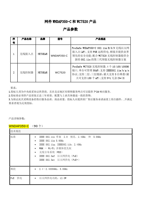
ProSafe™无线控制器WC7520为中小型企业、学校和医院设计的安全可靠的可扩展的无线控制器网件ProSafe 20-AP无线控制器WC7520提供了一个高性能、多功能的无线局域网架构,以满足中小型企业、学校和医院等环境多达1500个以上用户的需求。
为了易于使用,WC7520无线控制器简化了无线网络的部署和管理,同时拥有最好的无线可靠性、覆盖面和性能。
WC7520无线控制器的可扩展性让企业拥有非常大的投资回报,企业用户可以根据需求变化选择相应的licenses,从而扩展其无线网络。
通过升级licensing,ProSafe 无线控制器不但能够扩展到支持50个接入点,而且能够支持新一代的IEEE 802.11n接入点。
对于大型的网络部署,WC7520控制器通过3个单位的堆叠,实现冗余的同时能够支持多达150个接入点。
为了适应往后更多应用的需要,WC7520控制器提供了集中式的无线管理,综合了无线的灵活性,强大高端的安全性能,丰富的管理应用如二层/三层的快速漫游、captive portal客人访问认证、支持Wi-Fi Voice。
最后,WC7520提供了企业级的接入和安全的无线局域网连接。
可升级的架构体系WC7520控制器能够支持IEEE 802.11a/b/g,通过升级WC75NL license可支持IEEE 802.11n。
WC7520控制器本身可以支持20个接入点,升级一次WC7510L licenses,可以增加10个接入点,最多可以支持50个接入点。
可以实现3个控制器的堆叠,1组堆叠的WC7520控制器可以通过一个接口连接150个接入点。
更重要的是,WC7520提供了可靠的不间断的令人放心的冗余技术。
集中管理相对目前的有线网络的部署架构而言,NETGEAR的ProSafe 20-AP 无线控制器能够通过一个单一端口管理整个无线网络,从而简化了网络管理。
WC7520控制器安装非常简单,即使是跨越VLAN和子网,它也能够发现网络中可以支持的接入点。
AP 如何发现并且关联WC7520 无线控制器WC7520 发现AP 主要是通过2种方式:二层广播和指定IP 范围。
WNDAP350 和WNAP210 要支持被WC7520管理,必须升级成瘦AP模式,如果当AC发现的AP为胖AP模式时,会在关联的时候自动的将AP升级成为瘦AP模式,不需要手工升级,下面介绍一下具体的配置操作:1、网络拓扑如下:2、WC7520 默认管理IP 是192.168.0.250,用户名admin,密码password点击”LOGIN”进入管理界面。
2、在关联AP之前首先要确认网络中一定要存在有DHCP服务,否则AC只能发现AP而无法关联AP,这里启用WC7520的DHCP服务功能。
点击Configuration->System->DHCP Server 菜单右下角的ADD 将会弹出一个Add DHCP Server 窗口。
默认是四个以太网口都属于不打TAG标记的VLAN 1,所以去掉Use VLAN Interface 后面的勾注意:如果在这里起用了这个Use VLAN Interface,那么就可以创建相应的VLAN并且设置对应的DHCP,而且四个以太网口同时也会被打上相应VLAN的TAG标记;可以看到去掉Use VLAN Interface后面的勾以后,DHCP的网段会自动跟VLAN1的网段匹配,我们只要把起始IP和结束IP以及DNS地址输进去,然后点ADD就添加了DHCP服务了。
3、设置好DHCP服务后,点击Access Point->Discovery->Discovery Wizard菜单来选择发现AP的方式;∙如果都是出厂默认状态的AP,可以选择Factory default state方式来发现AP。
∙如果已经部署正常工作的状态的AP,可以选择Installed and working in standalone Mode方式来发现AP。
采购项目技术要求1.1.分包情况本项目共分为九个分包,具体情况如下:1.2.各分包详细的需求清单及其技术要求:一、计算机网络工程教学平台(FS70715088T01)数学建模教学平台(FS70715088T02)形态互动支持平台(FS70715088T03)四、数码媒体实验设备(FS70715088T04)长度200cm 高度77cm 宽度80cm,使用高密度板制作,表面铺贴防火材料。
色泽要求与学生台一致 。
台面平滑,预留一个电线孔。
台中间安装键盘 托盘,并安装横板放置音箱。
台最右侧为一个两 层柜约40cm 宽,右侧柜边留主机位一个30cm 宽, 主机位上留一柜桶。
左侧和右侧对称,所有柜要 安装柜门。
五、工业设计辅助教学平台(FS70715088T05)序号设备名称数量参考品牌型号技术要求及参数1台式电脑(PC )30台Dime nsion 9200CIntel Core2 Duo E6300 1.86G/ 内存 1G(2 X512M)/ 硬盘 160G/DVD+/-RW/液晶:19 寸 /ATIRadeo nX1300,128M2台式电脑(Apple )2台Apple Mac Pro MA356CH/A2.66QX/2X512/7300GT/250/SD-ITP/ M9 177CH/A 20" Flat Panel3笔记本电脑2台华硕 W7J W7K72J-SS 处理器:Intel Core2 Duo(Merom) T720 0(2.0G)/内存容量:1024M/硬盘容量:12 0G/光驱类型:内置,DVD-SuperMulti/ 屏 幕尺寸:13.3寸/显示屏类型:WXGA 显示 芯片:独立,NVIDIA GeForce Go7400/ 重 量:约 1.95Kg/ 操作系统:Windows Vista Home Premium4便携投影仪2台 索尼EX3亮度:2000ANSI 流明/投影机分辨率:102 4*768/投影机灯泡:165W UHP/重量:2.9 kg序号 设备名称 数量 参考品牌型号 技术要求及参数电源及网络布线:每个座位电源配两位万能二三 插,约43个座位,安装电源总箱一个,位置在图 中门口一侧,座位布置及课室大小如下图。
ZM602系列Wi-Fi模块用户手册Wi-Fi模块UM01010101 1.2 Date:2022/9/16类别内容关键词ZM602模块,Wi-Fi+BLE,用户手册摘要©2022 Guangzhou ZHIYUAN Electronics Co., Ltd.修订历史文档版本日期原因V1.00 2022.04.25 首次发布V1.01 2022.08.18 新增产品实物图;新增特色功能说明;更新产品选型表;优化快速使用说明;优化BLE数据透传说明;新增数据通道说明;新增串口命令:读取设备MAC地址、读取STA连接状态、读取连接到本设备的STA列表目录1. 产品简介 (1)1.1 概述 (1)1.2 产品特性 (1)1.3 典型应用 (2)1.4 产品选型表 (2)2. 快速使用说明 (3)2.1 与设备建立连接 (3)2.2 设置Wi-Fi工作模式 (4)2.3 使用设备连接其他热点 (5)3. 产品功能 (7)3.1 Wi-Fi数据透传 (7)3.1.1 场景一:模块数据互传 (7)3.1.2 场景二:模块与笔记本电脑进行数据互传 (12)3.2 BLE数据透传 (13)4. 工作模式 (16)4.1 网络工作模式 (16)4.1.1 数据通道 (16)4.1.2 TCP Server模式 (17)4.1.3 TCP Client模式 (18)4.1.4 UDP Client模式 (18)4.1.5 UDP Server模式 (18)4.1.6 MQTT Client模式 (19)4.2 Wi-Fi工作模式 (19)4.2.1 AP模式 (19)4.2.2 STA模式 (19)4.2.3 AP+STA模式 (19)5. 配置设备 (20)5.1 网页配置 (20)5.1.1 登录设备网页 (20)5.1.2 系统 (20)5.1.3 专家 (20)5.1.4 串口 (20)5.1.5 网络 (21)5.1.6 无线 (21)5.1.7 热点 (22)5.1.8 用户登录 (22)5.1.9 系统管理 (22)5.1.10 软件更新 (22)5.2 蓝牙快速配网 (23)5.3 串口协议指令 (25)5.3.1 基本原则 (25)5.3.2 封包结构 (26)5.3.3 命令列表 (28)5.3.4 事件列表 (28)5.3.5 命令解析 (29)6. 免责声明 (42)ZM602系列Wi-Fi模块用户手册Wi-Fi模块1.产品简介1.1 概述ZM602系列Wi-Fi模块是广州致远电子股份有限公司基于博流BL602系列芯片开发的高性能Wi-Fi+BLE模块产品。
CK7520B数控车床技术协议
甲方:安徽江淮汽车股份有限公司
乙方:宝鸡忠诚机床股份有限公司
甲乙双方本着友好合作、共同发展的原则就甲方向乙方订购两台宝鸡忠诚产CK7520B数控车床的有关事宜达成如下协议:
1、机床的基本配置
1)床身及底座(45度倾斜导轨,床身及底座整体式结构)
2)主轴箱(瑞典SKF主轴轴承)
3)纵向床鞍及驱动(德国亿孚滚珠丝杠、日本NSK丝杠轴承、配德国电
子限矩离合器、FANUC交流数字伺服电机)4)横向滑板及驱动(德国亿孚滚珠丝杠、日本NSK丝杠轴承、
配德国电子限矩离合器、FANUC交流数字伺服电机)5)卧式转塔刀架(意大利DM公司12工位电动刀架)
6)液压尾座
7)液压卡盘及油缸(台湾亿川12″中实液压卡盘及油缸,夹持φ265mm 反软爪两副、正软爪一副、标准硬爪一副)
8)液压动力单元(中港合资荣成机械有限公司产品)
9)自动润滑单元(中美合资南京贝切尔公司产品)
10)冷却泵站(韩国雅龙公司冷却泵、带过滤功能;配水枪系统一
套)
11)防护罩(全防护,带门锁保护功能)
12)CNC系统单元(FANUC 0i-TD数控系统、11/15KW广域交流数字伺
服主轴电机)
13)电气柜空调(宝鸡雷博)
14)排屑器及运屑车(中港合资荣诚机械有限公司链板式排屑器;运屑车采用两层屑水分离不易堵水阀)
15)机床三色灯
16)机床操作面板配手动换刀刀位选择开关;配两套X轴行程挡快
2、机床的主要规格及参数:
1)加工范围
床身上最大回转直径:Φ500 mm
最大车削直径:Φ370 mm
最大车削长度:500 mm
2)主轴
主轴头型式:(ASA)A2-8
轴通孔直径:Φ87 mm
主轴转速:30-3000 r/min
主轴电机功率: 11/15 kw
3)尾座
套筒直径/行程Φ90/100 mm
顶尖锥度(标准) MT NO. 5
4)床鞍
移动距离 X/Z 210/550 mm
快速移动速度 X/Z 12/16 m/min
滚珠丝杠直径 X/Z Φ28/Φ40 mm
5)刀架
刀位数 12
刀具尺寸(车削/镗孔) 25X25/Φ40 mm 6)其他
电源 45 kVA
总重量 4500 kg
体积(长X宽X高)2850X1800X1850 mm 3、机床随机附件清单
4、机床备件清单
5、刀附具规格
6、随机技术文件:
1、机床操作说明书
2、数控系统操作手册
3、数控系统维修手册
4、液压原理图
5、电气原理图、接线图
6、机床参数表及梯形图
7、机床参数软盘8、机床精度检验证书
9、液压卡盘手册10、转塔式电动刀架使用手册
7、机床验收、调试及培训
验收依据:
1)《卧式数控车床精度检验》 GB/T16462-1996;
2)《卧式数控车床技术条件》JB/T4368.3-96;机床防护标准:GB15760-1995;
3)金属切削机床通用标准;
4) 供方出厂检验文件;
5)本文规定内容的验收;
验收程序:
验收分预验收和终验收共两次
1)机床预验收,预验收在乙方工厂进行,终验收在甲方工厂进行。
A、按上述验收依据乙方自检合格后,将机床验收“成品检验记录表”传
真给甲方确认,并通知甲方到乙方现场进行预验收。
B、机床规格参数和主要配置验收,以符合本文约定内容为合格。
C、根据“成品检验记录表”对以下项目进行抽检,合格后转入下序验收;
有一项不合格,按“成品检验记录表”进行全检。
D、机床电气动作验收,以空运转4小时无故障为合格。
E、供方综合试件车削,以符合供方出厂检验文件为合格。
以上项目检验合格后,双方签署预验收纪要,机床预验收合格。
2)机床终验收
A、由乙方负责送货到甲方指定厂房内就位,设备就位后,甲方按供方随机提供的“机床调试准备情况表”将机床所需地基、电气、液压油、润滑油、冷却水等准备就绪后,发传真通知乙方;接到传真后,乙方安排有经验的调试工程师3-5天内抵达需方现场进行设备调试。
B、根据机床装箱单双方共同清点随机文件和随机附件,以符合机床装箱单和
本文约定内容为合格。
C、机床规格参数和主要配置验收,以符合本文约定内容和预验收纪要为合格。
D、机床调整水平,以符合机床使用说明书要求为合格。
E、按机床合格证明书抽检主轴的周期性轴向窜动和主轴卡盘定位锥面的径向
跳动,以符合机床合格说明书要求为合格。
F、机床电气动作验收,以空运转4小时无故障为合格。
G、该机床甲方用于前轮毂精加工(与乙方已供給甲方使用的CK7520机床所加
工的前轮毂精加工的工序及工艺相同),机床到达甲方安装验收CP值≥
1.33,验收时乙方负责进行对机床CP值的测试验证,并提供有效数据验证。
以上项目检验合格后,双方签署终验收纪要,机床调试和终验收合格。
H:验收调试期:25个工作日。
技术培训:
技术培训为全免费,并分两次进行:
1)机床预验收时,乙方接受甲方派出人员2-4名编程、操作及维修人员,在
乙方现场进行技术培训,内容包括机床机械、液压、电气等方面的理论和实际操作,
为期3天。
2)机床终验收时在需方现场进行技术培训,内容同上,以实际操作为主,为期1天。
8、机床售后服务
1)机床自终验收合格之日起“三包”一年,为全免费服务;除此以外,再延
长优惠服务一年,仅核收成本费(由需方失误造成的服务不在此列);随机附件
供应按机床随机附件一览表所列价格提供。
2)机床在使用过程中发现质量问题,接到需方通知后8小时内给予答复;需
方认为确需派员现场修机,则以传真方式通知供方,供方在48小时内派员抵达
现场修机,不排除故障不撤离现场。
3)三包期满后,供方负责终身提供广泛而优惠的备件供应和技术支持及服务。
9、本协议双方签字后有效,与对应合同具有同等法律效力。
甲方:安徽江淮汽车股份有限公司乙方:宝鸡忠诚机床股份有限公司
代表人:代表人:
日期:日期:。