
V7-1C18D8;中文规格书,Datasheet资料
- 格式:pdf
- 大小:106.43 KB
- 文档页数:2


minutes) •Salt Spray :48 hr with Nickel plating 500 hr with Olive Drab Cadmium•Fire Retardant / Low Smoke : UL94 V0 and NF F 16 101 & 1•Vibrations : 10 –500 Hz, 10 g, 3 axes : no discontinuity > 1m•Shocks : IK06 : weight of 250 g drop from 40 cm [15.75 in] on connectors (mated pair)•Humidity : 21 days, 43°C, 98% humidity •Temperature Range : -55°C / +85°CData rate400 Mbits/second over 4.5 metersMechanical•Tri-start thread coupling mechanism (MIL-DTL-38999 series III type) with anti-decoupling device•FW plug retention in the receptacle : 100 N in the axis •Mating cycles : 500 to 1500 timesCan be used with most IEEE 1394 cordset brands : No tools required!Assembly Instructions1.If a fully sealed (IP67) assembly is required: Install the white tape around the plug to cover the 4 holes of the overmolding. If there are no holes omit this step.2.Insert the black O Ring around the front face of the IEEE 1394 plug. This O Ring will ensure the seal.3.Insert the IEEE 1394 cordset into the metallic backshell.4.Insert laterally onto the cable the retention spacer (this spacer is soft so as to adapt to various overmolding styles) and slide the IEEE 1394 plug into this retention spacer.5.Insert the friction ring laterally onto the cable cordset.6.Insert the IEEE 1394 plug into the metallic circular shell. Note at this step that the main key is used for polarization. 7.Screw the backshell on the plug body. A spanner may be required to fully close the backshell to the circular shell.Important Note : The sealing of the connector is not done by theblack retention spacers which are sloted, but rather by the front face O-Ring (Fig 2).Plug AssemblyReceptacle Assembly(For Solder back-termination Styles only)To Solder your cable onto the PCB :1.Attach the 2 metallized plastic inserts around the PCB (Fig 1a & 1b).2.Insert the IEEE 1394 module from the rear of theconnector.123456721a1bRemoving Modules1.Insert the removal tool FWF ODE from the front 2.Push the module back with thumb.«6» Shell«2» Shell Square FlangeType 1 : IEEE 1394 ReceptacleType 2 : Solder6 Tined holes for solderingBack Terminations :7» Shell Jam Nut«2PE »and «7PE »Shellswith Backshell to protect the termination from dust, shocks and vibration.Backshell used with IEEE 1394Receptaclewith back-termination -(Type 1)Non sealedversionReceptacles :Panel DrillingPanel DrillingBackshell used with PCB Receptacle bactermination -(Type 2)S ealed version –IP67View of the PC Type 2version with 6 tined holefor solder terminationFrontBackPlug Cap Receptacle Capcap endSquare flange receptacle cap end Plug Cap endPanel Gasket for square flange receptacle (Thickness : 0,8 mm [.031]) : JE15分销商库存信息:AMPHENOLFWFTV22G FWFTV21G FWFTV72G FWFTV71G FWFTV6G FWFTV2PE1G FWFTV7PE1G FWFTVC2G FWFTVC6G FWFTVC7G。
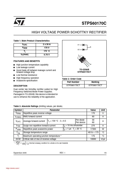
®1/6Table 1: Main Product CharacteristicsI F(AV) 2 x 30 A V RRM 170 V T j 175 °C V F (max)0.76 VSTPS60170CHIGH VOLTAGE POWER SCHOTTKY RECTIFIERREV. 1September 2005FEATURES AND BENEFITS■High junction temperature capability ■Low leakage current■Good trade off between leakage current and forward voltage drop ■Low thermal resistance ■High frequency operation ■Avalanche specificationDESCRIPTIONDual center tab Schottky rectifier suited for High Frequency Switched Mode Power Supplies.Packaged in TO-220AB, this device is intended for use to enhance the reliability of the application.Table 2: Order CodePart Number Marking STPS60170CTSTPS60170CTTable 3: Absolute Ratings (limiting values, per diode)Symbol ParameterValue Unit V RRM Repetitive peak reverse voltage 170V I F(RMS)RMS forward current 60A I F(AV)Average forward currentT c = 150 °C δ = 0.5Per diode Per device3060A I FSM Surge non repetitive forward current t p = 10 ms sinusoidal 270A P ARM Repetitive peak avalanche power t p = 1 µs T j = 25 °C17300W T stg Storage temperature range-65 to + 175°C T j Maximum operating junction temperature *175°C dV/dtCritical rate of rise of reverse voltage10000V/µs* : thermal runaway condition for a diode on its own heatsink dPtot dTj---------------1Rth j a –()-------------------------<STPS60170C2/6Table 4: Thermal Parameters Table 5: Static Electrical Characteristics (per diode)Pulse test:* tp = 5 ms, δ < 2%** tp = 380 µs, δ < 2%To evaluate the conduction losses use the following equation: P = 0.60 x I F(AV) + 0.053 I F 2(RMS)Symbol ParameterValue Unit R th(j-c)Junction to casePer diode Total 1.00.7°C/WR th(c)Coupling0.4When the diodes 1 and 2 are used simultaneously:∆ Tj(diode 1) = P(diode 1) x R th(j-c)(Per diode) + P(diode 2) x R th(c)Symbol ParameterTests conditions Min.Typ Max.Unit I R *Reverse leakage currentT j = 25 °C V R = V RRM35µA T j = 125 °C 835mAV F **Forward voltage dropT j = 25 °CI F = 30 A0.94VT j = 125 °C 0.720.76T j = 25 °C I F = 60 A0.97 1.05T j = 125 °C0.860.92STPS60170C3/6Figure 1: Average forward power dissipation versus average forward current (per diode)Figure 2: Average forward current versus ambient temperature (δ = 0.5, per diode)Figure 3: Normalized avalanche power derating versus pulse durationFigure 4: Normalized avalanche power derating versus junction temperatureFigure 5: Non repetitive surge peak forward current versus overload duration (maximum values, per diode)Figure 6: Relative variation of thermal impedance junction to case versus pulse durationTd =t /Tt pTd =t /Tt ptTd =t /Tt pSTPS60170C4/6Figure 7: Reverse leakage current versus reverse voltage applied (typical values, per diode)Figure 8: Junction capacitance versus reverse voltage applied (typical values, per diode)Figure 9: Forward voltage drop versus forward current (per diode, low level)Figure 10: Forward voltage drop versus forward current (per diode, high level)STPS60170C5/6Figure 11: TO-220AB Package Mechanical DataIn order to meet environmental requirements, ST offers these devices in ECOPACK® packages. Thesepackages have a Lead-free second level interconnect . The category of second level interconnect is marked on the package and on the inner box label, in compliance with JEDEC Standard JESD97. The maximum ratings related to soldering conditions are also marked on the inner box label. ECOPACK is an ST trademark. ECOPACK specifications are available at: .Table 6: Ordering Information■Epoxy meets UL94, V0■Cooling method: by conduction (C)■Recommended torque value: 0.55 Nm.■Maximum torque value: 0.7 Nm.Ordering type Marking Package Weight Base qtyDelivery mode STPS60170CTSTPS60170CTTO-220AB2.20 g50TubeTable 7: Revision HistoryDate RevisionDescription of Changes16-Sep-20051First issue.STPS60170CInformation furnished is believed to be accurate and reliable. However, STMicroelectronics assumes no responsibility for the consequences of use of such information nor for any infringement of patents or other rights of third parties which may result from its use. No license is granted by implication or otherwise under any patent or patent rights of STMicroelectronics. Specifications mentioned in this publication are subject to change without notice. This publication supersedes and replaces all information previously supplied. STMicroelectronics products are not authorized for use as critical components in life support devices or systems without express written approval of STMicroelectronics.The ST logo is a registered trademark of STMicroelectronics.All other names are the property of their respective owners© 2005 STMicroelectronics - All rights reservedSTMicroelectronics group of companiesAustralia - Belgium - Brazil - Canada - China - Czech Republic - Finland - France - Germany - Hong Kong - India - Israel - Italy - Japan - Malaysia - Malta - Morocco - Singapore - Spain - Sweden - Switzerland - United Kingdom - United States of America6/6分销商库存信息: STMSTPS60170CT。
