MIK-LCS2拉压力传感器
- 格式:doc
- 大小:124.50 KB
- 文档页数:1
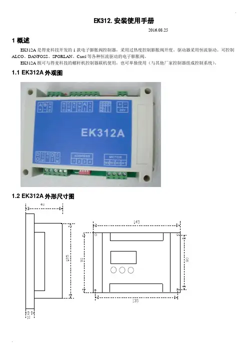
.EK312.安装使用手册-----2016.08.251 概述EK312A是得麦科技开发的1款电子膨胀阀控制器,采用过热度控制膨胀阀开度。
驱动器采用恒流驱动。
可控制ALCO、DANFOSS、SPORLAN、Carel等各种恒流驱动的电子膨胀阀。
EK312A既可与得麦科技的螺杆机控制器联机使用,也可单独使用(与其他厂家控制器组成控制系统)。
1.1 EK312A外观图1.2 EK312A外形尺寸图..1.3 EK312A 电气连接示意图EK312A电气连接示意图B-GA++-G TI DO W3W2W4AI +24G DI Com ComW1MotorB-GND A+ONOFF1234ON OFF1234O NO F FSW2JP2JP1JP3JP4JP5SW1VCCIout SW1地址1234OFF OFF 1ON OFF 2OFF ON 3ON ON4N LAC220VO N O FFSW212345V 10V举例1:12345123412312345612JP2-5设置为4-20mA输入O N O F FSW21234C V 5V 10V 举例2:JP2-5设置为0-10V输入O NO F FSW21234C V 5V 10V电子膨胀阀接线说明:ALCO膨胀阀:W4:白色W3:黑色W2:棕色W1:蓝色Danfoss膨胀阀:W4:黑色W3:白色W2:绿色W1:红色SPORLAN膨胀阀:W4:白色W3:黑色W2:绿色W1:红色Carel膨胀阀:W4:黄色W3:白色W2:棕色W1:绿色地址拔码说明:模拟输入拔码说明:报警输出启停开关电子膨胀阀24V电源输入压力传感器温度传感器通讯线运行故障通讯确认向上向下C V 0|10V0|5V 电压型电流型使用按键显示板备用注1:压力传感器接线:注2:压力传感器接线处,板内供电是24V ,如果传感器不是24V 供电,则要外接电源,之后将电源的负极接到板上的地(JP2-4)即可。

拉压力传感器又叫电阻应变式传感器,隶属于称重传感器系列,是一种将物理信号转变为可测量的电信号输出的装置。
下面就由该产品的研发生产销售厂家高灵传感具体介绍一下吧,希望可以帮助到大家。
目前拉压力传感器广泛运用在工业称重系统、平台秤、电子秤、吊钩秤、配料秤等测力场合。
在使用该产品之前,需要对以下几点知识有较清楚的了解。
一、拉压力传感器原理拉压力传感器是以弹性体为中介,通过力作用在帖传感器两边的电阻应片使它的阻值发生变化,再经过相应的电路转换为电的信号,从而实现后面的控制。
它的优点是精度高,测量范围广,寿命长,结构简单,频响特性好。
二、拉压力传感器特点(1)线性度:指传感器输出量与输入量之间的实际关系曲线偏离拟合直线的程度。
定义为在全量程范围内实际特性曲线与拟合直线之间的最大偏差值与满量程输出值之比。
(2)灵敏度:灵敏度是传感器静态特性的一个重要指标。
其定义为输出量的增量与引起该增量的相应输入量增量之比。
用S表示灵敏度。
(3)迟滞:传感器在输入量由小到大(正行程)及输入量由大到小(反行程)变化期间其输入输出特性曲线不重合的现象成为迟滞。
对于同一大小的输入信号,传感器的正反行程输出信号大小不相等,这个差值称为迟滞差值。
(4)重复性:重复性是指传感器在输入量按同一方向作全量程连续多次变化时,所得特性曲线不一致的程度。
(5)漂移:传感器的漂移是指在输入量不变的情况下,传感器输出量随着时间变化,这个现象称为漂移。
产生漂移的原因有两个方面:一是传感器自身结构参数;二是周围环境(如温度、湿度等)。
蚌埠高灵传感系统工程有限公司在自主创新的基础上开发生产出力敏系列各类传感器上百个品种,各种应用仪器仪表和系统,以及各种起重机械超载保护装置,可以广泛应用于油田、化工、汽车、起重机械、建设、建材、机械加工、热电、军工、交通等领域。
公司除大规模生产各种规格的高精度、高稳定性、高可靠性常规产品外,还可根据用户具体要求设计特殊的非标传感器,以满足用户的特殊要求。
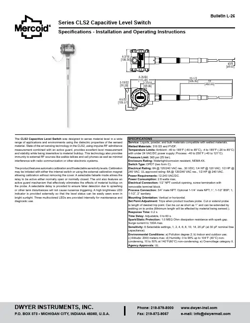
Series CLS2 Capacitive Level SwitchSpecifications - Installation and Operating InstructionsBulletin L-26The CLS2 Capacitive Level Switch was designed to sense material level in a wide range of applications and environments using the dielectric properties of the sensed material. State of the art sensing technology in the CLS2, using impulse RF admittance measurement combined with an active guard, provides excellent level measurement and stability while being insensitive to material buildup. This technology also provides immunity to external RF sources like walkie-talkies and cell phones as well as minimal interference with radio communication or other electronic systems.The product features automatic calibration and 8 selectable sensitivity levels. Calibration may be initiated with either the internal switch or using the external calibration magnet allowing calibration without removing the cover. A selectable failsafe mode allows the relay to be active either normally open or normally closed. The unit also features an active guard mechanism that effectively eliminates the effects of material buildup on the probe. A selectable delay is provided to ensure false detection due to splashing or other tank disturbances will not cause nuisance triggering. A high brightness LED indicator is provided externally so that the level status can be easily seen even in bright sunlight. Three multicolored LEDs are provided internally for maintenance anddiagnostic use.OPERATING PRINCIPLECapacitance and DielectricsCapacitance is the property of two or more conductors to store a charge when there is a voltage difference between the conductors. In other words, capacitance relates the voltage between two conductors and the amount of charge that can be held on the conductors (i.e., the number of electrons). Capacitance is measured in Farads, but since a Farad of capacitance represents a very large charge storage capacity, most capacitance encountered is generally measured in micro Farads (µF, 10-6) or pico Farads (pF, 10-12). Capacitances encountered in level sensing applications are generally in the pico Farad range.The material between the conductors also affects the capacitance. Insulating materials do not allow free movement of electrons, however, in an electric field the molecules of these materials will tend to align with the field, thus storing energy. This is called the dielectric effect and these materials are often referred to as dielectrics. When placed between two conductors the energy storage capability of these dielectrics will allow more charge to be stored on the conductors for a given voltage difference thus increasing the capacitance between the conductors. The ratio of capacitance change caused by these dielectrics is referred to as the dielectric constant. Different materials have differing dielectric constants and will consequently change the capacitance between two conductors more or less depending on the value of this constant. This value ranges from 1.0 for a vacuum to over 100 for certain materials. The dielectric constant for air is very close to 1.0 and usually assumed to be exactly 1.0.Capacitive level sensors determine the level of material by changes in probe capacitance resulting from the movement of dielectric materials between the probe and the reference ground such as a tank wall. Since measuring very small capacitance changes (less than 1 pF) can be problematic in industrial environments, capacitance level sensing tends to be most effective for materials with a dielectric constant greater than about 1.2. Since the difference in capacitance is being measured, it is also possible to detect the level of two immiscible liquids that have different dielectricconstants such as oil and water.Level DetectionThe CLS2 uses the capacitance difference between the uncovered sensor and covered sensor to sense level such as the probe in air verses the probe in oil. This would allow, for instance, detection when the level in a tank is below a threshold and a pump must be started or when the level is above a threshold where the pump must be turned off.The CLS2 can be used in applications were the probe gets coated or covered with sticky, dusty, or clingy materials. The CLS2 has an active guard near the top that compensates for material that coats the probe preventing false alarms.When detecting level, two critical items must be established: a reference capacitance and the sensitivity. The reference capacitance is set through an automatic calibration process. The sensitivity is selected using an internal DIP switch which provides 8 sensitivity levels to accommodate differing material dielectric constants. See the calibration section for specific calibration instructions.The level detection is available to external systems through a double pole double throw (2-form C) relay. In any alarm or control system some consideration must be made for a power failure in one or more elements of the system. The CLS2 provides a fail-safe selection that allows the relay to operate in either a normally open or a normally closed state when the probe is uncovered.INSTALLATION UnpackingRemove the CLS2 from the shipping carton and inspect for damage. If damage is found, notify the carrier immediately.Mounting LocationThe CLS2 is designed to be mounted in a tank and is rated for industrial environments with few restrictions, however certain considerations must be made to ensure optimal sensing and extended operational life.• The process temperature and ambient temperature must be within the specified limits for the instrument.• Avoid locating the unit near or in high mechanical shock or vibration areas. • The probe must be located away from tank inlets or chutes where material may fall on the probe during filling or emptying.• Avoid mounting the probe close to tank structures as conductive product bridging between the guard and tank structure can cause false alarms. • In nonmetallic tanks a ground reference must generally be provided. If the probe is near the wall of the tank an adhesive backed metallic sheet may be applied to the outside of the tank wall nearest to the probe. Other metallic objects may be used also if they are in close proximity to the tank wall. If the probe is located further than 10 inches from the wall, an internal conductor must be providedparallel to and within 10 inches of the probe. These conductors must be connected to the case ground of the sensor. An external ground clamp is provided for this ifother grounding is not available.Note: Installation must be made in accordance with National Electric Code and local codes and regulations. When fishing wire through the conduit connection do not allow the wire to touch or press on components on the boards. Damage to the circuitry may result.The unit is to be wired to a switch or circuit breaker in close proximity to the unit. The switch or circuit breaker shall be marked as the disconnections device for the unit.The CLS2 has a 1/2˝ female NPT conduit connection. The conduit connection must be made such that condensation is not allowed to enter the housing.Grounding: The case of the CLS2 must be wired to a protective earth ground. This may be done by using a metal conduit or by wiring to one of the protective earth groundscrews in Figure 1 or Figure 2.The terminal block may be removed for easier connection. To remove, place a small screwdriver between the terminal block and the connector base and pry the terminal block forward. This will unlatch the block from the base allowing it to be removed. When installing the block, tip it forward on the connector base to snap it in the forward locking tab then rock the connector back onto the contacts until it snaps in place. Make sure the terminal block is securely in place.Strip 0.25˝ of insulation from the wires. Connect the power wires to terminals 1 and 2. If powered by DC, the polarity is not critical and either terminal may be selected for positive or negative. Connect control lines to the relay contact terminals (see Figure 1 for terminals). Torque terminals to 5 in-lb.Controls and Indicators (See Figure 2 and 3)Calibrate Switch —Pressing this switch twice initiates the automatic calibration process.Time Delay Potentiometer—This control selects a delay time from 0 to 60 seconds from the detection of a level change to the output.Dip Switch —This four section switch selects the sensitivity level and failsafe mode.Sensor LED —Yellow. This LED is illuminated immediately when the probe capacitance exceeds the setpoint threshold.Output LED —Red. This LED is illuminated when the relay is powered. It is affected by the failsafe setting and the delay.Power LED —Green. This LED is illuminated when the unit is powered and indicates that power is being supplied to the sensing circuitry.External LED—Red. The external LED indicator operates in conjunction with the internal Output LED.External Calibration Magnet —An external magnet is provided on the end of a chain to initiate calibration without having to open the case. Calibration is started by touching the magnet to the label target twice.Always install or service this device with the power off and whererequired install a disconnect lockout.For power line connections use NEC Class 1 wiring rated 75°C. Use 12 to 20 AWG copper only for line and load connections.Torque terminals to 5 in-lb. Strip the wires 0.25˝.Protective earthL1Figure 1: TerminalsExternal LED(YELLOW)Power LED (GREEN)(RED)Calibrate Time delay External calibration magnetProtective earthground screwFigure 2: Swiches and LED’sPrinted in U.S.A. 10/20FR# 443401-00 Rev. 9©Copyright 2020 Dwyer Instruments, Inc.Setup and Calibration1. Fail Safe Mode Selection: The relay will always be off when the power fails. In this case the contacts identified as normally open will be open. The fail safe switch selects whether the normally open contacts are open or closed when the probe is uncovered. There are two options for the failsafe condition that are selected by DIP switch S4 (see Figure 2). Selecting normally open (NO) will force the relay contacts to be open when the probe is uncovered and the output status LED to be off.Selecting normally closed (NC) will energize the relay when the probe is uncovered and light the output status LED.2. Sensitivity Selection: The sensitivity must be selected to match the dielectric constant of the material and its density. Eight sensitivity levels are provided by positioning DIP switches S1, S2, and S3 (see Figure 2). A high sensitivity setting is a low pF, and a low sensitivity setting would be a high pF. High sensitivity is used for materials such as plastic pellets, light powders, and dry grain. Mediumsensitivity is used for materials such as cement, petroleum products, and flour. Low sensitivity is used for products such as aqueous solutions. The switchpositions are summarized in Table 1. For best operation use the minimal sensitivity required for reliable operation.3. Calibration: Calibrate with the probe uncovered and the material at least 5 inches below the probe.To start the automatic calibration process press the calibrate switch twice (see Figure 2) or press the external magnet up to the housing at the marked location on the housing twice (see Figure 3). The external magnet is attached to the housing by a chain. The output status LEDs will begin to blink slowly, about once per second, when the calibration process has started. The automatic calibration will take approximately 10 to 15 seconds, and the output status LEDs will stop flashing at the end of the calibration process. If during the calibration process the tank level changes or a sensor failure has occurred, the calibration process may fail. The output status LEDs will begin to flash rapidly (about 4 times per second). Makesure the probe is uncovered and retry the calibration step.Table 1: Switch position for sensitivityFigure 3: Magnent location4. Time Delay Selection: The time delay is the programmed time between when the probe senses the material and when the relay changes state from the sensed material. A time delay of 3 seconds or greater is required to meet CE requirements. Choose a delay setting appropriate for the specific application. Adjust the delay potentiometer to the desired delay (see Figure 2). The delay can be set anywhere from 0 to 60 seconds and a scale is printed on the sensor board. For verification of delay programming the yellow sensor LED will come on when material is sensed and the red output LED will come on with the relay after the programmed time delay.5. Verify Operation: Make sure the probe is uncovered, material at least 5 inches below the probe, and that the yellow sensor LED is off. Fill the tank until thematerial is at the desired threshold level and verify that the sensor LED is illuminated. If the sensor LED turns on before the material reaches the probe, reduce the sensitivity as needed. If when the probe is covered the sensor LED is notilluminated, increase the sensitivity. Water or other conductive liquids will activate the sensor when they just contact the probe. Low density and dielectric constantmaterial may require more of the probe to be covered.Note: Default values as the product ships from the factory is a follows: S1:off, S2:off, S3:on, S4:on, and time delay off.MAINTENANCEOther than the controls mentioned in this manual there are no user maintenance adjustments or routine servicing required for this product. Very heavy buildup on the probe may ultimately reduce sensitivity. Moderate buildup is compensated for by the active guard.The Series CLS2 Capacitive Level Switch is not field serviceable and should be returned if repair is needed (field repair should not be attempted and may void warranty). Be sure to include a brief description of the problem plus any relevant application notes. Contact customer service to receive a return goods authorization (RGA) number before shipping.When the CLS2 with a Sanitary Process Connection is to be used in a sanitary or hygienic application, the unit must be cleaned and/or sanitized in accordance with appropriate guidelines prior to installation. The CLS2 with a Sanitary ProcessConnection is suitable for “Clean In Place” methods.Explanation of Symbols:。

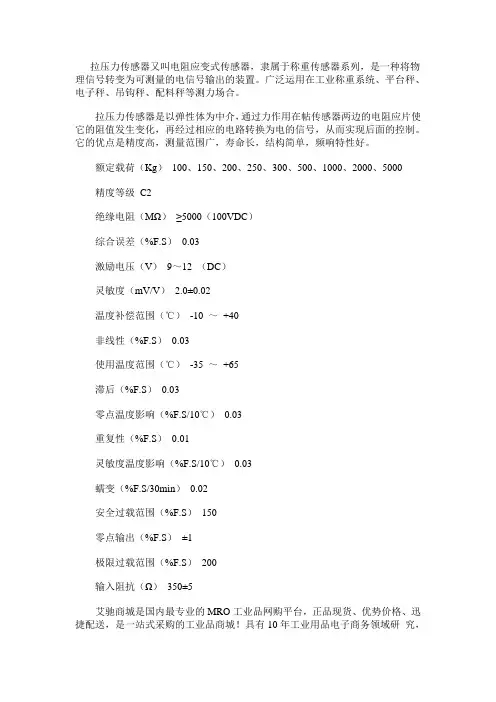
拉压力传感器又叫电阻应变式传感器,隶属于称重传感器系列,是一种将物理信号转变为可测量的电信号输出的装置。
广泛运用在工业称重系统、平台秤、电子秤、吊钩秤、配料秤等测力场合。
拉压力传感器是以弹性体为中介,通过力作用在帖传感器两边的电阻应片使它的阻值发生变化,再经过相应的电路转换为电的信号,从而实现后面的控制。
它的优点是精度高,测量范围广,寿命长,结构简单,频响特性好。
额定载荷(Kg)100、150、200、250、300、500、1000、2000、5000精度等级C2绝缘电阻(MΩ)≥5000(100VDC)综合误差(%F.S)0.03激励电压(V)9~12 (DC)灵敏度(mV/V) 2.0±0.02温度补偿范围(℃)-10 ~+40非线性(%F.S)0.03使用温度范围(℃)-35 ~+65滞后(%F.S)0.03零点温度影响(%F.S/10℃)0.03重复性(%F.S)0.01灵敏度温度影响(%F.S/10℃)0.03蠕变(%F.S/30min)0.02安全过载范围(%F.S)150零点输出(%F.S)±1极限过载范围(%F.S)200输入阻抗(Ω)350±5艾驰商城是国内最专业的MRO工业品网购平台,正品现货、优势价格、迅捷配送,是一站式采购的工业品商城!具有10年工业用品电子商务领域研究,以强大的信息通道建设的优势,以及依托线下贸易交易市场在工业用品行业上游供应链的整合能力,为广大的用户提供了传感器、图尔克传感器、变频器、断路器、继电器、PLC、工控机、仪器仪表、气缸、五金工具、伺服电机、劳保用品等一系列自动化的工控产品。
如需进一步了解图尔克、奥托尼克斯、科瑞、山武、倍加福、邦纳、亚德客、施克等各类传感器的选型,报价,采购,参数,图片,批发信息,请关注艾驰商城/。
拉压力传感器原理1. 前言随着科技的不断发展,传感器在工业、农业、医疗等领域得到广泛应用。
拉压力传感器作为一种常用的传感器,可以感知物体受到的力,并将其转化为电信号输出,被广泛应用于负荷测量、控制系统、智能家居等领域。
本文将深入探讨拉压力传感器的原理及其应用。
2. 拉压力传感器工作原理2.1 拉压力传感器构造拉压力传感器主要由弹性体、负载膜片、电桥和电路组成。
弹性体用于承受物体施加的力,其特点是具有一定的弹性和变形能力。
负载膜片是弹性体上的一个金属薄膜,当外力作用于弹性体时,负载膜片发生变形。
电桥是将负载膜片的变形转化成电信号输出的重要组成部分。
电路用于对电桥的信号进行放大和处理,最终输出一个与受力大小成正比的电信号。
2.2 拉压力传感器工作原理拉压力传感器的工作原理基于电阻的变化。
当外力作用于传感器时,弹性体产生变形,进而使负载膜片产生变形。
负载膜片上的金属薄膜的变形会导致电阻的变化。
拉压力传感器中常采用的是应变片(Strain Gauge)作为负载膜片,应变片是一种电阻变化率极高的电阻片,在压力作用下可以产生较大的电阻变化。
应变片的工作原理是基于金属或半导体材料在受力下发生变形,从而改变了内部微观结构,进而影响材料的电阻。
当应变片受到拉力时,其电阻值增加;当受到压力时,其电阻值减小。
通过测量电阻的变化,拉压力传感器可以转换成相应的电信号输出。
3. 拉压力传感器的应用3.1 负荷测量拉压力传感器在负荷测量领域有着广泛的应用。
在工业机械领域,拉压力传感器可以用于监测机械设备的负荷变化,实时了解设备的工作状态,从而进行负荷控制和故障诊断。
在物流仓储领域,拉压力传感器可以用于货物称重和跟踪,提高物流效率。
此外,拉压力传感器还可以应用于汽车动力传动系统、建筑起重机械等领域的负荷测量。
3.2 控制系统拉压力传感器也被广泛应用于各种控制系统中。
在机械加工中,拉压力传感器可以用于监测加工过程中受力状态,实现自动控制和优化加工质量。

拉压力传感器工作原理拉压力传感器是一种常见的传感器,用于测量物体受到的拉力或压力。
它的工作原理基于拉压力对传感器的变形产生的电信号。
本文将详细介绍拉压力传感器的工作原理。
一、拉压力传感器的构成拉压力传感器通常由以下几个主要部分构成:1. 拉压力敏感元件:它是传感器的核心部件,负责将受到的拉力或压力转化为电信号。
常见的拉压力敏感元件有应变片、电阻应变计和压阻式传感器等。
2. 桥式电路:拉压力传感器通常采用桥式电路来测量变形产生的电信号。
桥式电路由拉压力敏感元件、电阻和激励电源组成,通过电桥平衡来测量变形产生的微小电压信号。
3. 信号处理电路:它负责放大、滤波和线性化拉压力传感器输出的电信号,以便于后续的数据处理和分析。
二、拉压力传感器的工作原理拉压力传感器的工作原理可以分为以下几个步骤:1. 激励电源加电:通过给拉压力传感器的激励电源施加恒定电压,使其进入工作状态。
2. 变形引起电阻变化:当物体受到拉力或压力时,拉压力敏感元件会发生微小的变形,从而引起电阻值的变化。
这种变化可以是电阻值增加或减少,取决于拉压力敏感元件的类型。
3. 桥式电路平衡调节:拉压力传感器通常采用桥式电路来测量变形产生的电信号。
在初始状态下,桥式电路的各个电阻值是相等的,处于平衡状态。
但由于拉压力敏感元件的变形引起的电阻变化,导致桥式电路失去平衡,产生微小的电压差。
4. 电桥平衡调节:为了测量这个微小的电压差,需要通过调节桥臂上的电阻值来使电桥重新平衡。
根据电桥平衡的原理,可以通过调节一个或多个电阻的阻值来实现平衡调节。
5. 信号处理和输出:当桥式电路重新平衡后,可以得到一个与拉力或压力成正比的电压信号。
这个信号经过信号处理电路的放大、滤波和线性化处理后,输出给后续的数据采集和分析系统。
三、拉压力传感器的应用领域拉压力传感器广泛应用于工业自动化、机械设备、汽车、航空航天等领域。
具体的应用包括但不限于以下几个方面:1. 力学测试和研究:拉压力传感器可以测量物体受到的拉力或压力,用于力学测试和研究,例如材料强度测试、结构力学分析等。
Extend Pressure Measurement into High Temperature ApplicationsIntroductionMeasurement of pressure plays a central role in many areas of a plant, in the manufacturing industry, in machine tooling, in process engineering, and in the manufacture and processing of food andbeverages. Pressure measurement in industrial applications typically occurs with the help of pressure transmitters and switches. Pressure transmitters deliver a continuous current or voltage signal proportional to the pressure applied. Pressure switches are used to monitor pressure. Electronic pressure switches are characterized by their digital switching outputs, which are activated or deactivated when the defined, programmable threshold levels have been reached.Monitoring, measuring, and controlling pressure can be tricky if the process temperature exceeds the limits of the pressure instrumentation, such as pressure transmitters and switches. It is possible to obtain an accurate pressure measurement using standard pressure transmitters in these high temperature applications. The trick is to ensure that the process is cooled before reaching the pressure measuring device.There are generally two different methods used to protect the pressure transmitter and/or the pressure switch from high temperatures. These two proven methods are done through the use of coolingelements and standoff piping. Provided below are guidelines on how to protect the pressure devices from extreme temperatures using cooling elements and standoff piping.Cooling ElementsA cooling element is an accessory that puts some distance between the transmitter and the heat of the process. There are often times “fins” that allow for air circulation for betterheat dissipation. Cooling elements are designed to cool the process to a temperature that is within the specifications of the pressure transmitter.Cooling elements are a great way to protect the transmitter from high temperature processes. Cooling elements act as a heat sink, which cools the process before it reaches the transmitter.Cooling elements can extend the maximum process temperature of pressure transmitters from 185 °F (85 °C) up to 392 °F (200 °C).Figure 1: Cooling element.Figure 2: Cooling element attached to PBS Pressure Transmitter, Switch, and Display.Cooling elements from SICK provide heat protection as shown in the tables below. For the PBS electronic pressure switch, pressure transmitter and display; cooling elements can protect within the following guidelines:Chart 1: Temperature range of PBS pressure transmitter, switch, and display when installed with a cooling element (°F).PBS maximum process temperature when installed without a cooling element is 185 °F.For the PBS electronic pressure switch, pressure transmitter and display; cooling elements can protect within the following guidelines:Chart 2: Temperature range of PBS pressure transmitter, switch, and display when installed with a cooling element (°C).PBS maximum process temperature when installed without a cooling element is 85 °C.Chart 3: Temperature range of PFT pressure transmitter when installed with a cooling element (°F).PFT maximum process temperature when installed without a cooling element is 212 °F.For the PFT pressure transmitter; cooling elements can protect within the following guidelines:Chart 4:Temperature range of PFT pressure transmitter when installed with a cooling element (°C).PFT maximum process temperature when installed without a cooling element is 100 °C.Chart 5: Temperature range of PBT pressure transmitter when installed with a cooling element (°F).PBT maximum process temperature when installed without a cooling element is 176 °F.For the PBT pressure transmitter; cooling elements can protect within the following guidelines:Chart 6: Temperature range of PBT pressure transmitter when installed with a cooling element (°C).PBT maximum process temperature when installed without a cooling element is 80 °C.If cooling elements do not provide enough cooling to meet the application, standoff piping / impulse lines may be used.Standoff PipingUsing standoff piping (otherwise known as impulse lines) cools the process before it comes in contact with the pressure transmitter. Standoff piping may also allow the user to relocate the transmitter to a more convenient location for maintenance.Impulse line lengths are calculated using a general rule of thumb. For every 100 °F that the temperature needs to drop, users need to have 1 foot of impulse lines. For instance the maximum process temperature specification of the PBS pressure transmitter, switch, and display is 185 ° F (85 °C). If the process temperature is 585 °F, the process would have to be cooled 400 °F to be within the transmitter specification (585 - 185 = 400). Where 585 is the process temperature in °F, 180 is the maximum process temperature of the PBS, and 400 is the decrease in the temperate required for the transmitter. Dropping the process temperature by 400 °F is easily done using a minimum of 4 feet of impulse lines. This is a general rule of thumb, assuming a 68 °F (20 °C) ambient temperature. For higher ambient temperatures, longer impulse lines are required. For lower ambient temperatures, shorter impulse lines are required. Also, most users add a little more pipe length for added peace of mind.If the impulse lines are too long, other problems may present themselves:•Damping of the pressure signal•Blockage of the pressure signal•Leakage at couplingsTherefore, a balance between just long enough and too long must be achieved. Piping diameters should be as follows:Type of measured fluidImpulse Line Length0-52.5 ft (0-16 m) 52.5-148 ft (16-45 m) 148-295 ft (45-90 m)Water/steam and dryair/gas0.27-0.35 in (7-9 mm) 0.4 in (10 mm) 0.51 in (13 mm) Wet air/wet gas 0.51 in (13 mm) 0.51 in (13 mm) 0.51 in (13 mm) Oils of low mediumviscosity0.51 in (13 mm) 0.75 in (19 mm) 0.98 in (25 mm) Very dirty fluids 0.98 in (25 mm) 0.98 in (25 mm) 1.50 in (38 mm)Table 1: Impulse line diameters from ISO2186:1973Type of metered fluid Impulse Line Length0-52.5 ft (0-16 m) 52.5-148 ft (16-45 m) Water/steam and dry air/gas0.27-0.35 in (7-9 mm) 0.4 in (10 mm) Wet air/wet gas 0.51 in (13 mm) 0.51 in (13 mm) Oils of low medium viscosity0.51 in (13 mm) 0.75 in (19 mm) Very dirty fluids0.98 in (25 mm)0.98 in (25 mm)Table 2: Impulse line diameters from ISO/CD 2186:2004Gas ApplicationsMount hardware upward to allow moisture to drain out and not fill the impulse piping:• Slope impulse piping at least one inch per foot(8 centimeters per meter) downward from the transmitter toward the process connection.Liquid ApplicationsMount hardware downward to allow the escape of trapped vapor in the impulse piping:• Slope impulse piping at least one inch per foot(8 centimeters per meter) upward from the transmitter toward the process connection. • Vent all gas from the liquid piping legs.• Prevent sediment deposits in the impulse piping.ConclusionThere are generally two different methods used to protect the pressure transmitter and/or the pressure switch from high temperatures. These two proven methods are cooling elements and standoff piping. Some of the time a combination of both methods is used to give the engineer added peace of mind. By using either method, a standard pressure transmitter and/or pressure switch may be used in high temperature applications.Figure 4: Mounting hardware for liquid applications.Figure 3: Mounting hardware for gas applications.。

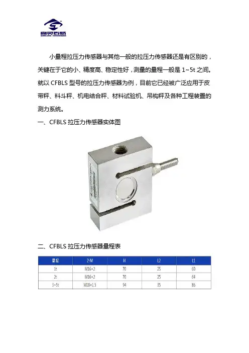
小量程拉压力传感器与其他一般的拉压力传感器还是有区别的,关键在于它的小、精度高、稳定性好,测量的量程一般是1~5t之间。
就以CFBLS型号的拉压力传感器为例,目前它已经被广泛应用于皮带秤、料斗秤、机电结合秤、材料试验机、吊钩秤及各种工程装置的测力系统。
一、CFBLS拉压力传感器实体图
二、CFBLS拉压力传感器量程表
三、CFBLS拉压力传感器外形图
四、CFBLS拉压力传感器指标数据表
蚌埠高灵传感系统工程有限公司在自主创新的基础上开发生产出力敏系列各类传感器上百个品种,各种应用仪器仪表和系统,以及
各种起重机械超载保护装置,可以广泛应用于油田、化工、汽车、起重机械、建设、建材、机械加工、热电、军工、交通等领域。
公司除大规模生产各种规格的高精度、高稳定性、高可靠性常规产品外,还可根据用户具体要求设计特殊的非标传感器,以满足用户的特殊要求。
如果您想进一步的了解,可以直接点击官网高灵传感进行在线了解。
辽宁工程技术大学机电设备与管理自考本科论文辽宁工程技术大学机电设备与管理自考本科毕业论文题目:煤矿带式输送机保护控制系统设计准考证号:姓名:指导老师:摘要带式输送机是一种由摩擦驱动引起连续动作的运输机械。
随着煤矿机电一体化水平的不断提高,煤矿井下带式输送机使用越来越广泛,台数越来越多,运距越来越长,在带式输送机的使用过程中经常出现一些打滑、跑偏、堆煤、烟雾、超温等故障,影响煤矿生产和安全。
为了避免这些事故的发生,带式输送机保护器孕育而生。
它不仅可以时时监视皮带的状态,还可以在皮带出现故障时进行报警,且对皮带的状态予以改变,进行保护。
带式输送机保护器的应用,使皮带有了可靠的保护。
本文设计的带式输送机保护控制系统主要用于对带式输送机的保护和控制,具有九大保护功能,其是在现有的八大保护基础上加入粉尘保护,分别为:速度保护、堆煤保护、跑偏保护、烟雾保护、温度保护、沿线紧急停车、撕裂保护、张紧力保护、粉尘保护。
可语言报警及显示故障类型,具有集中控制和单台操作功能。
同时,系统还增加了张紧和跑偏自动调整控制,使潜在的故障自动排除。
本论文结合DSP技术、单片机技术和传感器技术,对带式输送机的保护控制系统进行设计。
其中,传感器负责数据的采集;DsP采用TI公司的TMs320LF2407型芯片,其用于接收传感器送来的信号并送给单片机显示,当信号超限时,发出语音报警,并控制相应的继电器的吸合;单片机采用Af89C51芯片,其用于接收DSP送来的信号,通过液晶显示屏显示故障类型。
根据系统的工作原理,本文对系统的软、硬件进行了设计。
由于带式输送机保护控制系统是一个多传感器系统,本文采用信息融合的方法,根据系统的融合结构模型及Kalman滤波算法和模糊逻辑法,对此多传感器系统的信息进行互补整合,使得到的融合结果对检测环境的描述更准确,从而增加了传感器系统的可信度。
经试验分析,本文设计的带式输送机保护控制系统可以有效地做到保护、控制带式输送机,且通过显示和通一讯使工作人员更好的了解带式输送机的现状和予以控制。
S型拉压力传感器在我们的工业区当中使用也是非常的广泛,目前很多中小型企业都比较重视S型拉压力传感器的故障维修知识培训。
下面由S型拉压力传感器的厂家高灵传感为大家详细介绍下该设备的相关常识,帮助大家对该产品有较全面的认识。
对于已损坏的称重传感器的维修,我们一般不主张用户自己修理,有故障后希望能返送生产厂,由生产厂给予修理。
因为在称重传感器的修理中,若处理不当,尽管看起来已修“好”了,但可能会造成工作始终不稳定的后果。
以下就单只传感器进行详细说明:1、可能引发零点变化的因素分析(1)过载,往往会导致零点突变,输出电阻明显超出规定值;(2)冲击,同上;(3)受潮或受腐蚀,往往表现为零点的持续变化、不稳等,此时,绝缘电阻会有所降低。
检测方法:保证传感器无负载、尽可能模拟使用状况的条件下,按照传感器的正常接线方式,在输入端施加5~12V直流电压,在输出端使用电压计测量输出电压变化,该变化与输入电压之比,折算成mV/V,与标准灵敏度(单位同为mV/V)进行比较,不应超过±1%。
2、可能引发绝缘不良的因素分析(1)传感器电子元气件受潮,会导致绝缘电阻有所降低;(2)传感器电子元气件受到化学腐蚀,同上;(3)传感器内部线路、弹性体、屏蔽间出现短路,其阻值往往低于1KΩ。
检测方法:使用50V超绝缘计,分别检测弹性体(外露金属部分)、屏蔽线、输入输出芯线两两之间的电阻大小,其值不应低于5000MΩ。
特别注意的是:*千万不可使用绝缘计表笔测量输入和输出电阻;*对数字传感器,不能使用绝缘计进行阻抗测试。
3、可能引发桥路破坏的因素分析(1)传感器内部电器连线开路或短路;(2)器件烧损。
[检测方法] 使用电阻表,对输入、输出电阻进行测量,与出厂检验值进行比对,存在明显的改变,可判断为该故障。
4、可能引发冲击阻值变化的因素分析(1)传感器内部电器连接上出现虚焊;(2)应变计或其他粘贴件的胶层遭受破坏。
检测方法:同1、连接方式,使用木锤轻轻敲击传感器,要求传感器的输出信号不得有不稳定的变化。
拉/压力传感器(轮辐式),F2822型示例:型号F28222A D P R 1X 914113.01 07/2021 C N威卡(WIKA )操作说明,F2822型© 07/2021 WIKA Alexander Wiegand SE & Co. KG 保留所有权利。
WIKA ®是威卡(WIKA )在各个国家的注册商标。
在开始任何工作之前,请仔细阅读操作说明!请妥善保管以备后用!型号F2822操作说明页码 3 - 203威卡(WIKA )操作说明,F2822型A D P R 1X 914113.01 07/2021 C N目录1. 一般信息 42. 设计与功能 52.1 型号F2822概述 . . . . . . . . . . . . . . . . . . . . .52.2 描述 . . . . . . . . . . . . . . . . . . . . . . . . .52.3 供货范围........................53. 安全 63.1 符号说明........................63.2 预期用途........................63.3 不当使用........................73.4 操作人员责任 . . . . . . . . . . . . . . . . . . . . . .73.5 人员资质........................83.6 个人防护设备 . . . . . . . . . . . . . . . . . . . . . .83.7 标签/安全标识......................94. 运输、包装和储存 104.1 运输 . . . . . . . . . . . . . . . . . . . . . . . . 104.2 包装和储存 . . . . . . . . . . . . . . . . . . . . . . 105. 调试、运行 115.1 调试前注意事项 . . . . . . . . . . . . . . . . . . . . 115.2 安装说明.......................115.3 拉/压力传感器安装 . . . . . . . . . . . . . . . . . . . 125.4 电气连接.......................145.5 连接放大器 . . . . . . . . . . . . . . . . . . . . . . 145.6 引脚分配 型号F2822. . . . . . . . . . . . . . . . . . . 146. 故障 157. 维护和清洁 167.1 维护 . . . . . . . . . . . . . . . . . . . . . . . . 167.2 清洁 . . . . . . . . . . . . . . . . . . . . . . . . 167.3 再校准 . . . . . . . . . . . . . . . . . . . . . . . 168. 拆卸、返修和处置 178.1 拆卸 . . . . . . . . . . . . . . . . . . . . . . . . 178.2 返修 . . . . . . . . . . . . . . . . . . . . . . . . 178.3 处置 . . . . . . . . . . . . . . . . . . . . . . . . 179. 规格 189.1 认证 . . . . . . . . . . . . . . . . . . . . . . . . 1910. 附件 19附件:欧盟符合性声明 204威卡(WIKA )操作说明,F2822型A D P R 1X 914113.01 07/2021 C N1. 一般信息■操作说明中描述的拉/压力传感器均采用先进的技术进行设计和制造。
Sensor Selection GuideSensing for Building ApplicationsCO 2SensorsThe Honeywell CO 2 sensor includes state-of-the-art non-dispersive infrared (NDIR) technology plus a corrosion-free-designed sensing chamber that provides accurate and stable CO 2 readings for years, avoiding costly and inconvenient re-calibration. A patented gold-plated sensing chamber eliminates a primary source of dirt. Paired with a Honeywell economizer, theHoneywell CO 2 sensor can triple year-round savings over “cooling only” economizing. The sensor is used in demand control ventilation applications to maintain acceptable levels of CO 2 in the space.Differential Pressure SensorsAll Honeywell differential pressure sensors offer field selectable 4-20 mA, 0-5 Vdc and 0-10 Vdc outputs, uni- and bi-directional outputs, push button and digital inputs to zero the output, and configurable pressure ranges. Use P7640 dry media sensors in applications where you want measure extremelylow pressure, such as clean rooms, hospitals, fume hoods and computer rooms. Use the PWT Series to monitor and control pump differential pressure, chiller/boiler differential pressure drop and CW/HW system differential pressure.Enthalpy SensorsHoneywell enthalpy sensors are used with Honeywell economizer logic modules to permit the use of outdoor air as the first stage of cooling in HVAC systems. Thelong-lasting solid-state sensing elements are accurate and stable over time. Maximum economizer savings are achieved when two enthalpy sensors are connected to one economizer logic module for differential enthalpy changeover control.Specify Honeywell Sensors And SaveHoneywell sensors have always been competitively priced, and today Honeywell sensors continue to be one of the industry’s best values. Add in the fact that their ease-of-installation increases your productivity and you’ll see that Honeywell sensors are the smart, cost-effective choice.2Honeywell’s complete line of sensor's cover all necessary control applications and mounting options, making Honeywell your best sensor source.Temperature SensorsYou can count on Honeywell temperature sensors for the latest technology, accurate performance and reliability. Honeywell temperature sensors feature solid-statecomponents and are impervious to dust and dirt.They cover a variety of applications that will fit your needs from averaging, immersion and outdoor sensors to duct-mount, wall mount and strap-on sensors.Current Sensors And SwitchesHoneywell current switches can detect whether current is flowing and then transmit the status to a building management system, DDC or PLC controller. Honeywellcurrent transmitters measure the level of operating current and can be used to monitor equipment or drive other equipment with a modulating output. Both current switches and transmitters can be used to detect a motor failure, belt loss or slippage, or a mechanical failure to help prevent further damage and reduce downtime. Because Honeywell current sensors are rated at up to 250 amps, you can meet high-amp applications without the need for a transformer. And Honeywell offers current switches with a very low trip point of 0.20 amps.Humidity SensorsHighly accurate, stable humidity transducers designed for use with HVAC controllers, thermostats and direct digital controllers, Honeywell humidity sensors feature a ceramic technology that’s affected by condensation. Applications include room comfort, rooftop units, air handlers, air conditioning and anywhere relative humidity is tightly controlled.Dew Point SensorsSuitable for mounting on flat and round surfaces, the Honeywell dew point sensor is used to regulate cooling performance, switch cooling systems ON and OFF, andsignal if the temperature is approaching the dew point.YOUR BeST SeNSOR SOURCe3thermostats and non-Honeywell thermostats with remote setpoint.* F or accessing virtually any point in thecontroller, balancing from wall module, etc. **TR75s also have over twice as much memory capacity for parameters as TR71's.4GeNeRAL TeMPeRATURe SeNSORST775-SENS-STRAPT775-SENS-OATT775-SENS-WRT775-SENS-WT50021579-001aFor use with T7350 applications. bFor use with W7100.* May be used with Duct Mounting Kit- Part # 50053060-001GeNeRAL TeMPeRATURe SeNSORS5NOTE: 20K ohms NTC sensors are used with excel 10, 15, 50, 100 and 500. See controller product data sheets for details. PT1000 sensors are used with excel 15, 100, 500, and 600. See controller product data sheets for details. PT3000 sensors are used on certain excel and Microcell products. See controller product data sheets for details. 3K ohm NTC sensors are used on W7100, W7459, W7215, W7212 an dall economizer modules. 10K ohms NTC Type II sensors are used with TB7600, TB7300, and TB7600 Series communicating thermostats. 10K ohms NTC Type III sensors are used with WeBs-AX I/OModules.C7041PC7041JC7041BTB-WALLC7041DC7041FC7041R6CURReNT SeNSORSSplit CoreSolid Core7HUMIDITY , DeW POINT, CO 2and PReSSURe SeNSORSH7655B, H7625B, H7635BC7600B, H7655AC7262A1008C7232BHSS-DPSAutomation and Control Solutions In the US: Honeywell1985 Douglas Drive North Golden Valley, MN 55422-3992In Canada: Honeywell Limited 35 Dynamic Drive Toronto, Ontario M1V 63-9285 PR October 2013© 2013 Honeywell International Inc.P7640BHUMIDITY , DeW POINT, CO 2and PReSSURe SeNSORS (CONT.)50035430PWT250Follow us on Twitter: @honeywellcproYouTube:@honeywellcpro。