3S Lift 免爬器
- 格式:pdf
- 大小:3.05 MB
- 文档页数:2

全国3D大赛作品助老助残爬楼梯机器人说明书一、产品概述全国3D大赛作品——助老助残爬楼梯机器人,是一款专为老年人和残障人士设计的辅助设备。
本产品设计目的在于提供一种能够方便、安全、高效地帮助他们上下楼梯的解决方案。
通过精密的机械设计和先进的控制系统,本产品能够有效地提升使用者的上下楼梯能力,减轻他们的负担,提高生活质量。
二、产品特点1、安全性:本产品设计首要考虑的是使用者的安全。
采用稳定的机械结构和防滑材料,确保在使用过程中不会发生意外。
同时,设有紧急停止按钮,可在必要时立即停止机器运行。
2、易用性:操作简单,使用者只需轻轻推动控制杆,即可轻松上下楼梯。
同时,设有语音提示功能,引导使用者进行操作。
3、适应性:本产品设计考虑了不同使用者的需求,可以通过调节座椅和脚踏板的位置来适应不同身高和使用者需求。
4、节能性:采用高效电机和节能设计,保证机器在运行过程中的能源消耗最小化。
三、使用方法1、开启:按下开启按钮,机器人将自动识别楼梯并开始运行。
2、操作:推动控制杆来控制机器人的上下移动。
向上推动控制杆,机器人将向上爬楼梯;向下推动控制杆,机器人将向下爬楼梯。
3、停止:在任何时候,按下紧急停止按钮,机器人将立即停止运行。
4、关闭:在完成使用后,按下关闭按钮,机器人将自动返回待机状态。
四、注意事项1、使用前请仔细阅读本说明书,了解机器人的操作方法和注意事项。
2、请在安全环境下使用本产品,避免在潮湿、高温或极寒环境中使用。
3、请勿让儿童或未经训练的人使用本产品,避免发生意外。
4、使用过程中,如遇任何问题或故障,请立即停止使用,并售后服务。
5、在使用结束后,请关闭机器人,以节约能源并延长机器寿命。
五、售后服务我们提供全面的售后服务,包括产品咨询、使用指导、维修保养等。
在使用过程中遇到任何问题,您可以随时我们的客服团队,我们将尽快为您解决问题。
同时,我们也提供定期的保养服务,以确保您的机器始终处于良好的工作状态。
3S Lift助爬器操作使用说明书Operation Instruction Manual of 3S Lift Climbing Aid System中际联合工业技术(北京)有限公司3S Lift, Division of Ficont Industry Inc.3S Lift助爬器操作使用说明书Operation Instruction Manual of 3S Lift Climbing Aid System中际联合工业技术(北京)有限公司3S Lift , Division of Ficont Industry Inc.地址:北京市通州区宋庄佰富苑工业区6号邮编:101118Add:No.6 Baifuyuan Industry Zone, Songzhuang, Tong Zhou District, Beijing, China, 101118电话Tel:86 010-********传真Fax:86 010-********网址Web:邮箱E-mail:sales@24小时服务热线24-Hour service hotline:40000-24580 版本Version:F3S Lift助爬器操作使用说明书中际联合工业技术(北京)有限公司目录1. 符号说明 (2)2. 注意事项 (4)3. 产品描述 (8)3.1产品概述 (9)3.2产品原理及使用 (10)3.3特点 (11)3.4产品技术参数 (12)3.5助爬器的组成 (13)4. 操作方法 (18)5. 保护身体的安全设备 (20)6. 日常检测与维护 (20)6.1日常检查 (20)6.2保养 (21)7. 故障与维修 (23)8. 包装 (24)第1页/ 共24页3S Lift助爬器操作使用说明书中际联合工业技术(北京)有限公司1. 符号说明符号关键词意义造成的后果注意潜在的危险受伤或设备损坏安全保护穿安全服严重受伤安全手套戴安全手套严重受伤安全帽戴安全帽严重受伤第2页/ 共24页3S Lift助爬器操作使用说明书中际联合工业技术(北京)有限公司符号关键词意义造成的后果安全带系安全带严重受伤危险可能的危险受伤或设备损坏重要工作中的有效建议无有关说明第3页/ 共24页3S Lift助爬器操作使用说明书中际联合工业技术(北京)有限公司2. 注意事项危险!助爬器不适用于低于18岁或少于50公斤体重的人员,为避免发生意外,请仔细阅读操作说明书后进行操作!a)有专业设备操作技术资格的人员才能安装、操作和维护助爬器及安全设备。
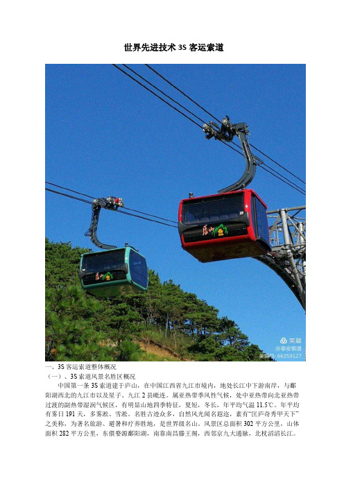
世界先进技术3S客运索道一、3S客运索道整体概况(一)、3S索道风景名胜区概况中国第一条3S索道建于庐山,在中国江西省九江市境内,地处长江中下游南岸,与鄱阳湖西北的九江市以及星子、九江2县毗连。
属亚热带季风性气候,处中亚热带向北亚热带过渡的副热带湿润气候区,有明显山地四季特征,夏短,冬长,年平均气温11.5℃。
年平均有雾日191天,多雾淞、雪淞。
名胜古迹众多,自然风光闻名遐迩,素有“匡庐奇秀甲天下”之美称,为著名旅游、避暑和疗养胜地,是世界级名山。
风景区总面积302平方公里,山体面积282平方公里,东偎婺源鄱阳湖,南靠南昌滕王阁,西邻京九大通脉,北枕滔滔长江。
耸峙于长江中下游平原与鄱阳湖畔。
“长江南岸鄱湖畔,拔地庐山风景妍;峭壁陡崖飞瀑布,奇峰秀岭绕云烟”,庐山多峭壁悬崖,瀑布飞泻,云雾缭绕。
自东北向西南延伸约25公里,宽约15公里。
东西两侧为大断裂,相对高度1200~1400米。
主峰汉阳峰海拔1474米,山势雄伟。
胜迹有白鹿洞、仙人洞、观音桥、周瑜点将台、爱莲池、三叠泉、含鄱口等。
庐山风景区,1982年被国务院颁布为首批国家重点风景名胜区;1996年以“世界文化景观“列入《世界遗产名录》,2002年被评为“中华十大名山”之一;2006年被国家文明委、建设部、旅游局命名为“全国文明风景旅游区”称号;2008年被评为AAAAA级旅游景区。
(二)、建设3S索道的意义近几年来,随着中国旅游经济的迅猛发展,庐山风景名胜区作为闻名于世的风景名胜区,伴随内外部交通设施和旅游服务配套设施的建设与完善,发展势头喜人,2011年风景区接待游客164.3万人次。
庐山,作为我国十大名山之一,与客运索道渊源极深。
据文献记载,庐山山下至山顶的登山交通索道项目历数次筹划而未果。
最早可追溯至民国八年(公元1919年),德籍工程师葛乐尔拟有莲花洞至牯岭的钢绳挂车计划。
民国二十五年,江西省政当局鉴于牯岭为训练各项人才之基地,山路崎岖,交通不便,故有登山吊车之筹划,并施行了初步测勘之工作,后因故中止。

INSTALLATION INSTRUCTIONS# 30630 ’87 –‘96YJ 3” LIFT KITWarrior recommends this system be installed by a certified technician. In addition to these instructions, professionalknowledge of disassembly and reassembly procedures as well as post installation checks must be known. Attempts to install this system without this knowledge and expertise may jeopardize the integrity and/or operating safety of the vehicle.Please read instructions before beginning installation. Check the kit hardware against the parts diagram. Be sure you have all needed parts and know where they go.With the installation of all lift kits and larger tires it is important to check the condition of your steering stabilizer. If thestabilizer is worn or is leaking it should be replaced. Steering stabilizers are designed to restrain “bump steering” and front end vibration, giving added life to tires, ball joints, and other steering components . A large bore off-road stabilizer kit is highly recommended for vehicles equipped with larger tires.PRODUCT USE INFORMATIONAs a general rule, the taller a vehicle is, the easier it will roll. Offset, as much as possible, what is lost in rollover resistance by increasing tire track width. In other words, go "wide" as you go "tall". Many sportsmen remove their mud tires after hunting season and install ones more appropriate for street driving; always use as wide a tire and wheel combination as possible to enhance vehicle stability.We strongly recommend, because of rollover possibility, that the vehicle be equipped with a functional roll-bar and cage system. Seat belts and shoulder harnesses should be worn at all times. Avoid situations where a side rollover may occurGenerally, braking performance and capability are decreased when significantly larger/heavier tires and wheels are used. Take this into consideration while driving.Do not add, alter, or fabricate any factory or after-market parts to increase vehicle height over the intended height of the Rough Country product purchased. Mixing component brands is not recommended.Warrior makes no claims regarding lifting devices and excludes any and all implied claims. We will not be responsible for any product that is altered.If question exist we will be happy to answer any questions concerning the design, function, and correct use of our products.NOTICE TO DEALER AND VEHICLE OWNERAny vehicle equipped with Warrior Suspension System products should have a “Warning to Driver” decal installed on the inside of the windshield or on the vehicle’s dash. The decal should act as a constant reminder for whoever is operating the vehicle of its unique handling characteristics.INSTALLING DEALER - it is your responsibility to install the warning decal and forward these installation instructions on to the vehicle owner for review. These instructions should be kept in the vehicle for its service life.INSTALLATION INSTRUCTIONS1. Raise the front of the vehicle and support with safety stands.2. Remove the front wheels and tires. Remove stock shocks.3. Support the front axle housing with a floor jack (you must have stands under frame supporting vehicle weight).4.Unbolt tracking bar from the housing on the axle and then tie the bar up and out of the way (see figure 3 for relativelocation).5. The upper end of the front brake hoses attach to the top of each frame rail with one bolt located directly behind theshock towers (see figure 2). Remove the bolts (access is gained through the engine compartment).6. Remove the four front spring to axle u-bolts. (The remainder of the spring removal and installation is performed oneside at a time.)7. On the driver side position a floor jack beneath the axle tube, just inside of the leaf spring. Raise the jack until the axlejust separates from the spring. Now remove the frame bolts and the shackle bolts on the leaf spring. Repeat on the other side.8. Prior to installation of new springs, thoroughly lubricate the new spring poly eye bushings and sleeves with “water resistant” lithium based grease. Loosely attach the spring to its hangers, snug up but do not completely tighten yet. Make sure spring centering pin aligns and seas into spring perch hole.9. While installing new u-bolts, put one bump stop extension snubber on top of axle tubes. (figure 1 shows how the bump-stops are capture by the u-bolt. Tighten u-bolts to 65 ft. lbs. of torque. Tighten spring pivot bolts to 35ft. lbs. on both frame mounts and shackle mounts.10. To install new tracking bar bracket onto front axle housing, refer to instructions with Front Trac Arm Bracket.11. Assemble and install new front shock absorbers P art #60501 (Boot installation and poly hourglass bushing installation can made easier with the use of rubbing alcohol sprayed on the poly as a lubricant.). Tighten upper stem type mounts only until bushings swell slightly, then torque lower mounts to 45 ft lbs.12. Install new front brake line relocating brackets (#700021) in stock holes reusing the bolts on the frame rail. Pull steel line out from the frame rail (Use caution when rerouting the steel line so you do not kink the line). Mount the line to the bracket using the 5/16” x 1” bolts, washers and flange lock nut. Note: There is a driver side and a passenger side bracket as shown in figure 2.13. Reinstall tires/wheels, remove jack stands and lower vehicle to floor. Tighten the front spring’s shackle to 95 ft. lbs. and the stationary end to 105 ft. lbs. (If kit includes pitman arm, you may want to do pitman arm instructions before proceeding to rear of vehicle)14. Once again as on the front (following same basic steps). Place safety (jack) stands under rear frame rails.15. Remove the retainer clip that attaches the stock rubber brake hose to its upper mount bracket. This is where the rubber hose ends and the metal line starts. Insert the new “Z” brackets in between the stock mounting bracket and the hose end. The 5/16” x 1” bolt and flanged lock nut are used to attach the bracket to the bracket end. Position the hose/line through the slot and into the hole on the “Z” bracket’s opposite end and then reinstall clip (See figure 5).16. Disconnect tracking bar from frame rail. Install new drop down tracking bar mounting bracket (#800005) on housing as shown in figure 4 using provided hardware.17. Install new springs (#800020) with shims. (torque u-bolts 65 ft. lbs.) Remember to install the bump stop extension snubber on as you did on the front. When installing the springs the thick part of shim goes toward front of jeep. Attach tracking bar to drop down bracket using original 12mm bolt and flange-nut. (torque to 45 ft. lbs.)18. Assemble the rear shock absorbers (Part# 60502) with loop bushings and corresponding sleeves and install shocks. Torque upper and lower mounts to 45-ft. lbs. On some models there may not be adequate clearance between the shock body and the axle tube. In this situation your only option is to relocate the shock bracket.19. Install tires, remove jack stands, and lower vehicle to floor. Tighten the shackle to 95 ft. lbs. and the frame end to 105ftlbs. 20. Install Transfer Case Spacer Kit following instructions packaged with part #800006. 21. Install Pitman Arm Kit following instructions packaged with part #800016Assemble as shown with brake line bracket mounted to the frame in the stock brake line location. Pull the steel line out from the frame and bolt it in the other hole on the bracket.Figure 2 - Brake line bracket New bump stop snubber.New rear track rod bracket Stock rear track rodStock track rodNew track rod bracketFigure 3Figure 4Track rod mounts hereMounts in stock track rod locationRear passenger side springParts ListFront Leaf Springs Kit Pitman Arm Kit YJ Bump Stop Bracket Kit800019 800016 800003 60501 Front Shocks- 2 60503 Rear Shocks- 2 Rear Leaf Springs Kit Transfer Case Spacer Kit YJ Frnt Trac Arm Brkt Kit 700004 Black Boots-4800020 800006 800004 700005 Black Cable Tie-4700021 Frnt Brk Ln Ext Brkt -2 Front U-Bolts Kit YJ Frnt Sway Bar Link Kit YJ Rr Trac Arm Brkt Kit 700022 Rr Brk Ln Ext Brkt -1 800021 800014 800005 BK2141 1 ¼” T-Bushings -8 BK2048 1 ½” T-Bushings -8Rear U-Bolts Kit¾” x 3” Sleeve -8 800022POST INSTALLATION INSTRUCTIONS1.Check all fasteners for proper torque. Check to ensure there is adequate clearance between all rotating, mobile,fixed and heated members. Check steering gear for interference and proper working order. Test brake system. 2.Perform steering sweep. Check to ensure brake hoses have sufficient slack and will not contact rotating, mobile, orfixed members, adjust lines/brackets to eliminate interference and maintain proper working order. Failure to perform inspections may result in component failure.3.Bump stops and extensions must be in place on all vehicles! Note: allowing suspension to over extend byneglecting to install or maintain stops and extensions may cause serious damage to OE and related components. 4.Re torque all fasteners after 500 miles. Visually inspect components and re torque fasteners during routine vehicleservice.MAINTENANCE INFORMATIONIt is the ultimate buyers responsibility to have all bolts/nuts checked for tightness after the first 100 miles and then every 1000 miles. Wheel alignment steering system, suspension and driveline systems must be inspected by a qualified professional mechanic at least every 3000 miles.。


J1.6-2.0UTT 3-WHEEL ELECTRIC FORKLIFT2OVERVIEWThe cost-effective Hyster UT series is a suitable option for less demanding applications, backed by the power of the Hyster name.THE RANGEThe J1.6-2.0UTT range is available in three different capacities:1,600KG – J1.6UTT 1,800KG – J1.8UTT 2,000KG – J2.0UTTDESIGNThe design of the UT range has been engineered with the driver in mind. The ergonomically designed operator compartment, with a wide range ofstandard features and options, can be configured to the needs of the operator and the application.1HIGH STRENGTH OVERHEAD GUARDThe profiled steel overhead guard features high strength materials to enhance reliability and operator protection.2AC CONTROLLERControllers optimize battery powerconsumption. AC traction and hydraulic motors improve precision. All are easily accessible to minimize service time.3WIDE AND LOW STEPThe conveniently positioned non-slip step coupled with large grab handles provide easy and secure access to the truck.4WIDE VIEW MASTThe wide view mast delivers excellent visibility of the load and operator’s forward field of view, optimizing comfort and productivity .5SMALL, ADJUSTABLE STEERING WHEELThe small diameter steering wheel requires low effort, promoting light and precise operation. The adjustable steer column optimizes comfort and convenience.6DUAL DRIVE MOTORSThe compact structure of the drive system provides adequate access for maintenance. Precision cut gears are incorporated, leading to reduced wear and lower noise levels.FEATURES24 53163LOW COST OF OWNERSHIPThe use of high quality and robust components within the UT series deliver a reliable operation with limited wear and tear. Maintenance costs and requirements are further reduced by simple, readily available, genuine and cost effective replacement parts. HYDRAULICSHigh quality cylinders with hard chrome rods reduce seal wear for long life. A full-flow, low pressure filter on the return line keeps the hydraulic oil clean, which helps to minimize seal and pump wear. In addition, this keeps the control valve in good condition, leading to low service costs.4ENGINEERED FOR DRIVERSSAFETY AND COMPLIANCE• H igh visibility, shock absorbing mast enables soft landing• C ontrollable mast lowering speed helps to avoid damage• Secure overhead guard • Standard LED lights • O perator presence systemCOMFORT• H ydraulic power steering requires low steeringeffort for precise positioning • D river fatigue minimized by full suspension, superior comfort and lumbar support seat • A djustable steering column and seat to suit all operators• Low noise and vibration • L ow entrance step, large uncluttered floor space and ergonomically positioned pedals • E rgonomic handbrake and operator controlsPERFORMANCE• O n-demand hydraulic power steering, withtwin drive motor system, delivers superb maneuverability and low energy consumption • E xcellent stopping capability – deliveredthrough maintenance free oil-immersed brakes and regenerative braking system • S imple and clear dash display • D isplay with integrated performance selection functions • A C traction and lifting motors, with electronic control, helps improve performance • S equential seatbelt interlockSERVICE• A C traction and hydraulic motors help reducemaintenance costs • E asy service access to the controllers – mounted inside the counterweight, at waist height, protected by removable cover • I P54 Design – protects the hydraulic and drive motor components • R eadily accessible drivetrain – minimizing service time • C ANbus communication simplifies troubleshooting5Mast typeMax fork height (mm)Overall extended heightFree liftMast tilt Capacity without side shift Lowered height (mm)Lift heightWithout LBR(mm)With LBR (mm)Forward (Deg)Back (Deg)@ 500mm Single pneumatic tire (kg)@ 600mm Single pneumatictire (kg)Without LBR (mm)With LBR (mm)1.6T 1.6T 1.6T1.6T 1.6T 2LFL300019753490401035356616001435330021253790431035356616001435350022253990451035356616001435370023254190471035356616001435400025254490501035353516001435450027754990551035353514001255500030255490601035353512501120550033255990651035353511501030600035756490701035353510509402FFL3000197534904010151099066160014353300212537904310166011406616001435350022253990451017601240661600143537002325419047101860134066160013304000252544905010206015403516001330 3FFL400018504490501013858653516001330435019754840536015109903515001345450020254990551015601040351400125548002125529058101660114035130011655000222554906010176012403512501120550023905990651019251405351150103060002575649070102110159035105094065002790699075102325180535900805J1.6UTT MAST AND CAPACITY TABLENote: For integral sideshift deduct 50kg from stated capacityMAST SPECIFICATIONSMast typeMax fork height (mm)Overall extended heightFree liftMast tilt Capacity without side shift Lowered height (mm)Lift heightWithout LBR(mm)WithLBR (mm)Forward (Deg)Back (Deg)@ 500mm Single pneumatic tire (kg)@ 600mm Single pneumatictire (kg)Without LBR (mm)With LBR (mm)1.8T 1.8T 1.8T 1.8T 1.8T 2LFL300019753490401035356618001615330021253790431035356618001615350022253990451035356618001615370023254190471035356618001615400025254490501035353518001615450027754990551035353516001435500030255490601035353514501300550033255990651035353512001075600035756490701035353511009852FFL3000197534904010151099066180016153300212537904310166011406618001615350022253990451017601240661800161537002325419047101860134066180015004000252544905010206015403518001500 3FFL400018504490501013858653518001500435019754840536015109903517001525450020254990551015601040351600143548002125529058101660114035150013455000222554906010176012403514501300550023905990651019251405351200107560002575649070102110159035110098565002790699075102325180535950850J2.0UTT MAST AND CAPACITY TABLEMast typeMax forkheight (mm)Overall extended heightFree liftMast tilt Capacity without side shift Lowered height (mm)Lift heightWithout LBR (mm)With LBR (mm)Forward (Deg)Back (Deg)@ 500mm Single pneumatic tire (kg)@ 600mm Single pneumatictire (kg)Without LBR (mm)With LBR (mm)2.0T 2.0T 2.0T 2.0T 2.0T 2LFL3000197534904010545466200017953300212537904310545466200017953500222539904510545466200017953700232541904710545466200017954000252544905010545435200017954500277549905510545435180016155000302554906010545435150013455500332559906510545435130011656000357564907010545435120010752FFL3000197534904010151099066200017953300212537904310166011406620001795350022253990451017601240662000179537002325419047101860134066200016654000252544905010206015403520001665 3FFL400018504490501013858653520001665435019754840536015109903519001705450020254990551015601040351800161548002125529058101660114035165014805000222554906010176012403515001345550023905990651019251405351300116560002575649070102110159035120010756500279069907510232518053510008956SPECIFICATIONSD i s t i n g u i s h i n g m a r k 1.1Manufacturer MeasurementHyster Hyster Hyster 1.2Model designationJ1.6UTT J1.8UTT J2.0UTT 1.3Power: battery, diesel, LPG, electric mainsBattery Battery Battery 1.4Operation: manual, pedestrian, stand, seat, orderpicker Seated Seated Seated 1.5Load capacity Q (kg)1600180020001.6Load center c (mm)5005005001.8Load distance x (mm)3713713711.9WheelbaseY (mm)140014001515W e i g h t 2.1Unladen weight (max. battery)kg 3120319033802.2Axle loading, laden front / rear (max. battery)kg 4010 / 6604420 / 5104870 / 5802.3Axle loading, unladen front / rear (max. battery)kg 1480 / 16401500 / 16901580 / 1810T i r e s , c h a s s i s 3.1Tires: L=pneumatic, V=cushion, SE= superelastic SE SE SE 3.2Tire size, front 18 × 7-818 × 7-8200 / 50-103.3Tire size, rear15 × 4.5-815 × 4.5-815 × 4.5-83.5Number of wheels, front / rear (X = driven) 2x / 22x / 22x / 23.6Track width, front b10 (mm)9339339523.7Track width, rear(mm)186186186D i m e n s i o n s 4.1Mast tilt, forward α / back β degrees 6/66/66/64.2Height of mast, lowered h1 (mm)1992199219904.4Lift height “h3 (mm)3036303630454.5Height of mast, extended E h4 (mm)4030403040004.7Height to top of overhead guard m h6 (mm)2002200220044.8Seat height u h7 (mm)9659659654.12Towing coupling height h10 (mm)4454454854.19Overall length (with forks)l1 (mm)2894289431534.20Length to face of forks l2 (mm)1974197420844.21Overall width b1 (mm)1084108411404.22Fork dimensionss /e / l (mm)35 / 100 / 92035 / 100 / 92040 / 120 / 10704.23Fork carriage DIN 15173. class, A / B 2A 2A 2A 4.24Fork carriage width E b3 (mm)9509509504.25Width over forksb5 (mm)8908908904.31Ground clearance, laden, below mast m1 (mm)9090904.32Ground clearance at centre of wheelbasem2 (mm)9696964.33Aisle width with pallets 1000 mm long × 1200 mm wide Ast (mm)3290329034454.34Aisle width with pallets 800 mm wide × 1200 mm long Ast (mm)3415341534104.35Outer turning radius Wa (mm)1601160117164.36Inner turning radius b13 (mm)000P e r f o r m a n c e d a t a 5.1Travel speed laden / unladen km / h 14 / 1614 / 1614 / 165.2Lifting speed laden / unladen mm / s 352 / 500349 / 500310 / 5005.3Lowering speed laden / unladenmm / s 344 / 420382 / 421390 / 4305.6Maximum drawbar pull laden / unladen, 5 minute rating N 15500 / 1000015000 / 1050015500 / 120005.8Maximum gradeability with / without load, 5 minute rating %20 / 3020 / 3020 / 305.9Acceleration time with / without load 10m sec 4.4 / 4.3 4.4 / 4.3 5.9 / 5.65.10Service brakeHydraulic Hydraulic Hydraulic E l e c t r i c -m o t o r 6.1Drive motor rating, S2, 60min kW 2 × 5.0 2 × 5.0 2 × 5.06.2Lifting motor, S3 15% rating kW 1111116.3Battery DIN 43531 / 35 / 36 A, B, C, no 43531A 43531A 43531A 6.4Battery voltage / capacity (5hr rate)V/Ah 48 / 46048 / 46048 / 6006.5Battery weight (min / max)kg 9459451090Battery dimensionsl / w / h (mm)830 / 630 / 627830 / 630 / 627830 / 738 / 6276.6Power consumption in accordance with VDI cycle kWh / h 5.19 5.3 5.7A d d i t i o n a l d a t a8.1Drive control AC AC AC ManufacturerZAPI ZAPI ZAPI 8.2Operating pressure for attachments x bar 1451751758.3Oil volume for attachments Vmin 3838388.4Average noise level at operator's ear ¬dB (A)64.864.869.68.5Towing coupling, type DINØ32Ø32Ø32¬ L PAZ, measured according to the test cycles and based on the weighting values contained in EN12053“ Bottom of forksu Full suspension specified E Without load backrestm h6 subject to +/- 5 mm tolerance x VariableSpecification data is based on VDI 2198, with the following configuration: Complete truck with 3000mm 2-stage limited free lift mast, standard carriage and forks, overhead guard and standard superelastic drive and steer tires.7DIMENSIONSAst = Wa + x + l6 + aa = Minimum operating clearance of 200mm l6= load length7382X 152X 158306275805601802306302X 152X 15750680980ModelCompartment sizeBattery specifications Electrical Battery sizeWeightW mm (in)L mm (in)H mm (in)Voltage W mm (in)L mm (in)H mm (in)Min kg (lbs)Max kg (lbs)J1.6-1.8UTT Vertical extract 843 (33.1)634 (24.9)645 (25.3)48830 (32.6)630 (24.8)627 (24.6)898 (1980)992 (2185)J2.0UTT Vertical extract843 (33.1)752 (29.6)645 (25.3)48830 (32.6)738 (29.0)627 (24.6)1034 (1980)1142 (2515)Battery type: “EO” (without cover)Battery compartment length is measured front to rear. Battery compartment width is measured across the truck Battery lead: length 250mm (10”), bosition “B”, 2 / 0 AWGBATTERY COMPARTMENT SPECIFICATIONSJ1.6-1.8UTTJ2.0UTTHyster Company P .O. Box 7006Greenville, North Carolina 27835-7006Part No. J1.6-2.0UTT/BTG 3/2021 Litho in U.S.A.Visit us online at or call us at 1-800-HYSTER-1.Hyster, and STRONG PARTNERS, TOUGH TRUCKS, are registered trademarks in the United States and certain other jurisdictions. Hyster products are subject to change without notice.Trucks may be shown with optional equipment. © 2021 Hyster Company. All rights reserved.。
关于免爬器人机独立防坠落系统的问题解析免爬器人机独立、分离防坠落系统:车体与操作人员应有两套独立的防坠落系统,且工作于相互独立的导轨或钢丝绳上;在建项目安装免爬器时,爬梯的防坠落安全绳应保留,如爬梯防坠落系统使用的防坠落滑轨,则需更换为防坠落安全绳。
理由分析如下:ISO10333-4-2002Personal fall-arrest systems-Part4:Vertical rails and vertical lifelines incorporating a sliding-type fall arrester(人员坠落救护系统.第4部分:垂直下落和滑动型下落救护车连接的垂直升降索道)ISO10333-4-2002个体坠落防护系统-第四部分:带垂直导轨和垂直生命线的自锁器EN353-2-2002个体防护装备高空坠落防护-第二部分:导向型坠落制动器,柔性吊绳EN353-1-2002个体防护装备高空坠落防护-第一部分导向型坠落制动器,钢性吊绳GB24542-2009坠落防护带刚性导轨的自锁器GB23525-2009单人吊具悬吊作业安全技术规范从风力发电机结构来看,除了风电本身的电气危险和火灾,最大的风险就是高空坠落。
当风电工作人员进入塔筒,沿着梯子进行攀爬,到达机舱,再进入轮壳,甚至到机舱顶部进行作业,整个过程都面临着高空坠落的危险。
由于风电行业的设计原理所限,使得减少高空作业颇有难度,所以风电操作人员在高空作业时必须使用合适的防坠落装备,降低高空坠落的风险。
垂直方向上的防坠落系统,简称垂直生命线系统,做为坠落防护体系的一部分,由承重挂点、垂直绳索生命线或导轨生命线、防坠器以及坠落悬挂安全带(全身式安全带)四部分组成。
垂直生命线系统的作用是在作业人员于垂直方向移动或提升下降过程中,一旦主要保护系统(人员的手和脚或提升设备)失效时触发,启动辅助保护系统(生命线防坠落系统),用以保障作业人员的坠落防护安全。
此PDF电子文档支持以下功能**需阅读软件支持,以AdobeReader为例。
CRANE 3S 说明书Z H I Y U N -C N -v 1 . 1 0Contents■产品清单产品清单 (1)■认识CRANE 3S认识CRANE 3S (2)接口说明 (2)■电池及充电说明充电器及电池介绍 (3)■电池及充电说明充电步骤 (4)■安装及调平安装三脚架 (5)安装电池 (5)安装相机 (5)连接控制线 (7)调节平衡 (9)■稳定器的使用控制按键说明 (11)电机力度参数调节 (12)工作模式说明 (12)鳞甲3S简易提壶手柄安装及拆卸 (15)鳞甲3S提壶控制手柄安装及拆卸 (16)延长臂安装及拆卸 (17)手调定位 (19)■APP的使用下载APP (20)如何连接 (20)APP主要功能介绍 (20)■校准与固件升级哪种情况下需要校准 (21)初始化方法 (21)六面校准方法 (21)电机微调 (22)稳定器固件升级 (23)■参数说明■免责声明与警告阅读提示 (25)警告 (25)安全操作指引 (25)■保修卡质保期限说明 (28)质保不包括 (28)为获得ZHIYUN质保服务,请按下列步骤操作 (28)■联络卡产品清单产品清单使用本产品前,请仔细检查产品包装内是否包含以下所有物品,若有缺失,请联系客服或您的代理商。
快装板 x1镜头⽀撑架导管 x2增⾼垫 x1❶ CRANE 3S-E 版本包装中标配鳞甲3S 简易提壶手柄。
认识CRANE 3S认识CRANE 3S1.俯仰轴锁紧螺钉2. Type-C相机控制接口3.快装板底座锁紧扳手4.快装板安全锁5.快装板锁紧扳手6.航向轴锁定开关7.航向轴电机8. DC-IN电源输入接口9.跟焦滚轮10.云台摇杆11.俯仰轴电机12.俯仰轴锁定开关13.横滚轴锁紧螺钉14.横滚轴电机15.横滚轴锁定开关16.电池仓盖开关17. 3/8螺孔18. 1/4拓展螺纹冠齿19.底座触点20.三脚架21.1/4拓展螺孔22.延长臂安装座23.鳞甲 3S 提壶控制手柄安全锁24. 1/4拓展螺纹冠齿25.电源键&模式指示灯26. POV键27.拍照键28.录像键29. MODE键30.跟焦器接口×231.航向轴锁紧螺钉32. FN键33. USB-A电源输出口34. Type-C固件升级接口35.扳机键36. 3/8螺孔首次使用CRANE 3S产品,请使用包装内所提供的充电装置为您的电池充满电以激活电池并保证产品的顺利使用。
安全培训记录培训主题免爬器使用及日常维护培训培训对象培训时间培训地点主讲人应到人数参加人数培训内容:一、培训目的:1、了解掌握安全生产责任制具体内容;2、了解掌握安全生产法具体内容;3、提高员工安全生产责任意识及法律意识。
二、主要内容:3S lift免爬器是一种智能遥控的风机塔筒攀爬辅助升降设备,安装于竖梯底部的驱动箱,驱动一根通过上部支架连接到车体上部的钢丝绳带动车体做升降运动。
电控箱内的变频器及智能控制器保证电机提供给驱动绳轮一个合适的速度。
免爬器配备两套单独的防坠落系统:一套车体防坠系统,一套个人防护系统,双重保护高空作业人员的安全。
1.产品技术参数:2.使用注意事项:➢操作前,确保免爬器使用者经过专业的培训,并仔细阅读过操作与安装手册,持有操作资格证。
➢任何人在使用免爬器时,必须穿着个人防护用具(如安全帽、全身式安全带、安全双钩、3S专用防坠器)➢免爬器运行前,请确认免爬器运行通道无任何障碍物存在,尤其是平台盖板必须处于开启状态并固定好,以免造成人员伤害及设备的损坏。
➢免爬器运行前,请检查钢丝绳张紧指示标是否处于正常区域(绿区)。
➢免爬器运行前,请检查电源是否电量充足。
➢操作人员必须携带合适通讯设备,保持与地面人员或基站人员的通讯。
➢免爬器运行时,禁止任何人员处于免爬器的正下方或正上方。
➢免爬器运行时,禁止其他操作人员使用爬梯攀爬。
➢免爬器的遥控模式仅用于运送物料,禁止载人。
➢在操作中如果发现设备损坏或故障导致安全隐患时,必须立即停止使拼通知设备管理人员或业主。
➢火灾时禁止使用免爬器。
➢免爬器载物时必须配合载物框使用,载物框承重60Kg。
3.基本组成:4.操作方法:➢运行准备:将免爬器主电源接通,开启控制箱电源开关,按下启动按钮电源指示灯亮。
打开电池开关,确认电池电量,穿戴好安全带、挂好防坠器,开启免爬器小车急停按钮。
➢小车控制模式:将免爬器面板上的选择开关拨到上升或下降,双手同时按下扶手的启动开关时设备启动。
免爬器在风电项目运维中的运用作者:侯锐来源:《科技风》2020年第02期摘;要:国家政策大力扶持,风电行业新增装机规模巨大,2006年以后,我国风电行业发展迅速。
截至2017年底,我国累计装机容量达到188392MW,位居世界第一。
目前,在风力发电领域一般都需要高空作业。
在高空作业平台和地面之间输送人员物资以及检修都需要采用一定的升降设备。
这种升降设备还需要考虑到实际工作环境、安全性等多方面因素。
传统的提升机设施造价高,占用空间大,安装空间受限。
近年,中国风电市场转向低风速领域,高塔筒、长叶片、大功率成为发展趋势。
随着塔筒增高,对风电高空作业安全辅助设备需求会越来越大,“免爬器”的市场应运而生。
关键词:风电;免爬器;运用一、免爬器的定义免爬器是指安装在风力发电机组塔筒爬梯上的升降设备,利用爬梯上的导轨,是风机检修和维护人员上下塔筒使用的助力的设备,主要由车体、导轨、钢丝绳、驱动装置、控制系统等部分组成。
二、免爬器与助爬器的区别免爬器是发电机组塔筒攀爬的新型輔助设备,产品结构紧凑,在不改变塔筒内部结构安装于塔筒的爬梯上,具有安装方便、安全可靠、操作简单等特点,可以节省攀爬风机塔筒人员的体力消耗,能有效提高风机巡检和维护效率。
免爬器有两个突出特点:一是零体力消耗;二是可载物。
助爬器目前普遍应用于风力发电机组的塔筒内,助力器的助力范围30-50千克。
助爬器一般安装在竖梯上,作业人员通过身上的安全带挂钩与环绕在竖梯上的牵引绳连接,助力器电机驱动牵引绳,给作业人员提供助力。
助爬器具有质量轻,体积小,安装和操作简单,高可靠性等优点。
三、免爬器的结构免爬器一般由车体、导轨、钢丝绳、驱动装置、控制系统等部分组成。
车体是指承载人员的平台,含车身、踏板、扶手、操纵装置和安全锁等。
作业人员通过操纵装置平台升降,当车体由于钢丝绳断裂、曳引力不足等原因发生坠落时,安全锁将车体制停在导轨、钢丝绳或者爬梯上。
导轨安装在爬梯上,约束车体运行线路的刚性元件,作用是保持升降平台的运行平稳性,并能使安全锁能够可靠制停。