ASTM E112-2013 测定平均晶粒度的标准试验-培训讲稿
- 格式:pptx
- 大小:898.24 KB
- 文档页数:37
名称:E112-96(2004年重新核准)——平均晶粒度标准测试方法1这一标准是根据E112条款颁布的;E112之后紧跟的数字表示最初编辑的年份,或者表示最后修改的年份(如果有修改),括号内数字(如果有的话)则表示最终批准的年份,上标ε1表示从最后修改或批准之日起的一次编辑更换。
该标准被国防部各相关部门认可使用。
简介这些金属平均晶粒度测试方法根本上是测量过程。
因为这一过程完全是独立于金属及其合金材料的几何学问题。
实际上,这些基本方法也应用于评估非金属的平均晶粒、晶体及晶胞尺寸。
如果材料组织结构接近于标准对比图谱中的某一个图的话,可以采用对比法。
截距法和求积法也经常应用于确定平均晶粒度。
然而,对比法不能应用于单个晶粒的测量。
1 范围1.1 本标准规定了金属组织的平均晶粒度表示及评定方法。
这些方法也适用晶粒形状与标准系列评级图相似的非金属材料。
这些方法主要适用于单相晶粒组织,但经具体规定后也适用于多相或多组元和试样中特定类型的晶粒平均尺寸的测量1.2 本标准使用晶粒面积、晶粒直径、截线长度的单峰分布来测定试样的平均晶粒度。
这些分布近似正态分布。
本标准的测定方法不适用于双峰分布的晶粒度。
双峰分布的晶粒度参见标准E1181。
测定分布在细小晶粒基体上个别非常粗大的晶粒的方法参见E930。
1.3本标准的测量方法仅适用平面晶粒度的测量,也就是试样截面显示出的二维晶度,不适用于试样三维晶粒,即立体晶粒尺寸的测量。
1.4 试验可采用与一系列标准晶粒度图谱进行对比的方法或者在简单模板上进行计数的方法。
利用半自动计数仪或者自动分析晶粒尺寸的软件的方法参见E1382。
1.5本标准仅作为推荐性试验方法,它不能确定受检材料是否接收或适合使用的范围。
1.6 测量数值应用SI单位表示。
等同的英寸-英镑数值,如需标出,应在括号中列出近似值.1.7 本标准没有列出所有的安全事项。
本标准的使用者应建立适合的安全健康的操作规范和使用局限性。

ASTME2平均晶粒尺寸测试方法
该标准方法主要基于显微组织观察和测量晶粒的直径或等效圆周。
以下是该方法的一般程序:
1.样品制备:从需要测试的金属材料中取出一个表面平坦、无明显缺陷的试样。
样品可以通过切割、抛光和腐蚀等步骤来制备。
2.显微组织取样:根据材料的特点和测试要求,采用适当的金相试样制备方法来获取显微组织试样。
通常情况下,制备出的试样应包含横截面的金相显微组织。
3.显微观察:将显微组织试样放置在金相显微镜下进行观察。
选择适当的放大倍率和透光方法,以获得清晰、充分的晶界图像。
4.晶粒测量:使用合适的测量工具(如尺子、比例尺或图像分析软件等)对试样中的晶粒进行测量。
根据需要,可以直接测量晶粒的直径或等效圆周。
5.数据分析:根据测量得到的晶粒尺寸数据,计算出平均晶粒尺寸。
可以采用不同方法,如线性拟合、区域平均或统计分析等来计算平均值。
需要注意的是,ASTME112并未指定具体的测量设备和测量方法。
而且,该方法只提供了一种常用的晶粒尺寸测试方法,不同的材料和实验要求可能需要采用不同的方法和测量标准。
Designation:E112–96(Reapproved2004)e2Standard Test Methods forDetermining Average Grain Size1This standard is issued under thefixed designation E112;the number immediately following the designation indicates the year of original adoption or,in the case of revision,the year of last revision.A number in parentheses indicates the year of last reapproval.A superscript epsilon(e)indicates an editorial change since the last revision or reapproval.This standard has been approved for use by agencies of the Department of Defense.e1N OTE—Reference(2)was editorially corrected in May2006.e2N OTE—Equation A1.9was editorially corrected in November2006.INTRODUCTIONThese test methods of determination of average grain size in metallic materials are primarily measuring procedures and,because of their purely geometric basis,are independent of the metal or alloy concerned.In fact,the basic procedures may also be used for the estimation of average grain, crystal,or cell size in nonmetallic materials.The comparison method may be used if the structure of the material approaches the appearance of one of the standard comparison charts.The intercept and planimetric methods are always applicable for determining average grain size.However,the comparison charts cannot be used for measurement of individual grains.1.Scope1.1These test methods cover the measurement of average grain size and include the comparison procedure,the planimet-ric(or Jeffries)procedure,and the intercept procedures.These test methods may also be applied to nonmetallic materials with structures having appearances similar to those of the metallic structures shown in the comparison charts.These test methods apply chiefly to single phase grain structures but they can be applied to determine the average size of a particular type of grain structure in a multiphase or multiconstituent specimen.1.2These test methods are used to determine the average grain size of specimens with a unimodal distribution of grain areas,diameters,or intercept lengths.These distributions are approximately log normal.These test methods do not cover methods to characterize the nature of these distributions. Characterization of grain size in specimens with duplex grain size distributions is described in Test Methods E1181.Mea-surement of individual,very coarse grains in afine grained matrix is described in Test Methods E930.1.3These test methods deal only with determination of planar grain size,that is,characterization of the two-dimensional grain sections revealed by the sectioning plane. Determination of spatial grain size,that is,measurement of the size of the three-dimensional grains in the specimen volume,is beyond the scope of these test methods.1.4These test methods describe techniques performed manually using either a standard series of graded chart images for the comparison method or simple templates for the manual counting methods.Utilization of semi-automatic digitizing tablets or automatic image analyzers to measure grain size is described in Test Methods E1382.1.5These test methods deal only with the recommended test methods and nothing in them should be construed as defining or establishing limits of acceptability orfitness of purpose of the materials tested.1.6The measured values are stated in SI units,which are regarded as standard.Equivalent inch-pound values,when listed,are in parentheses and may be approximate.1.7This standard does not purport to address all of the safety concerns,if any,associated with its use.It is the responsibility of the user of this standard to establish appro-priate safety and health practices and determine the applica-bility of regulatory limitations prior to use.1.8The paragraphs appear in the following order:Section Number Scope1 Referenced Documents2 Terminology3 Significance and Use4 Generalities of Application5 Sampling6 Test Specimens7 Calibration8 Preparation of Photomicrographs9 Comparison Procedure101These test methods are under the jurisdiction of ASTM Committee E04onMetallography and are the direct responsibility of Subcommittee E04.08on GrainSize.Current edition approved Oct.23,2006.Published November2004.Originallyapproved st previous edition approved1996as E112–96e3.Copyright©ASTM International,100Barr Harbor Drive,PO Box C700,West Conshohocken,PA19428-2959,United States. --`,,,````,,,`,``,,`````,```,`-`-`,,`,,`,`,,`---Planimetric (Jeffries)Procedure 11General Intercept Procedures 12Heyn Linear Intercept Procedure 13Circular Intercept Procedures 14Hilliard Single-Circle Procedure 14.2Abrams Three-Circle Procedure 14.3Statistical Analysis15Specimens with Non-equiaxed Grain Shapes16Specimens Containing Two or More Phases or Constituents 17Report18Precision and Bias 19Keywords 20Annexes:Basis of ASTM Grain Size NumbersAnnex A1Equations for Conversions Among Various Grain Size Measurements AnnexA2Austenite Grain Size,Ferritic and Austenitic Steels AnnexA3Fracture Grain Size Method AnnexA4Requirements for Wrought Copper and Copper-Base Alloys AnnexA5Application to Special Situations AnnexA6Appendixes:Results of Interlaboratory Grain Size DeterminationsAppen-dix X1Referenced Adjuncts Appen-dix X22.Referenced Documents 2.1ASTM Standards:2E 3Practice for Preparation of Metallographic Specimens E 7Terminology Relating to MetallographyE 407Practice for Microetching Metals and AlloysE 562Practice for Determining V olume Fraction by Sys-tematic Manual Point CountE 691Practice for Conducting an Interlaboratory Study to Determine the Precision of a Test MethodE 883Guide for Reflected-Light PhotomicrographyE 930Test Methods for Estimating the Largest Grain Ob-served in a Metallographic Section (ALA Grain Size)E 1181Test Methods for Characterizing Duplex Grain Sizes E 1382Test Methods for Determining Average Grain Size Using Semiautomatic and Automatic Image Analysis 2.2ASTM Adjuncts:2.2.1For a complete adjunct list,see Appendix X23.Terminology3.1Definitions —For definitions of terms used in these test methods,see Terminology E 7.3.2Definitions of Terms Specific to This Standard:3.2.1ASTM grain size number —the ASTM grain size number,G ,was originally defined as:N AE 52G 21(1)where N AE is the number of grains per square inch at 100X magnification.To obtain the number per square millimetre at 1X,multiply by 15.50.3.2.2grain —that area within the confines of the original(primary)boundary observed on the two-dimensional plane-of-polish or that volume enclosed by the original (primary)boundary in the three-dimensional object.In materials contain-ing twin boundaries,the twin boundaries are ignored,that is,the structure on either side of a twin boundary belongs to the grain.3.2.3grain boundary intersection count —determination of the number of times a test line cuts across,or is tangent to,grain boundaries (triple point intersections are considered as 1-1⁄2intersections).3.2.4grain intercept count —determination of the number of times a test line cuts through individual grains on the plane of polish (tangent hits are considered as one half an interception;test lines that end within a grain are considered as one half an interception).3.2.5intercept length —the distance between two opposed,adjacent grain boundary intersection points on a test line segment that crosses the grain at any location due to random placement of the test line.3.3Symbols:Symbols:a =matrix grains in a two phase (constituent)microstructure.A =test area.A —=mean grain cross sectional area.AI ,=grain elongation ratio or anisotropy index for a longitudinally oriented plane.d —=mean planar grain diameter (Plate III).D —=mean spatial (volumetric)grain diameter.f =Jeffries multiplier for planimetric method.G =ASTM grain size number.,=mean lineal intercept length.,—a =mean lineal intercept length of the a matrix phase in a two phase (constituent)microstructure.,—,=mean lineal intercept length on a longitu-dinally oriented surface for a non-equiaxed grain structure.,—t =mean lineal intercept length on a trans-versely oriented surface for a non-equiaxed grain structure.,—p =mean lineal intercept length on a planar oriented surface for a non-equiaxed grain structure.,0=base intercept length of 32.00mm for defining the relationship between G and ,(and N L )for macroscopically or micro-scopically determined grain size by the intercept method.L =length of a test line.M =magnification used.M b =magnification used by a chart picture series.n=number of fields measured.2For referenced ASTM standards,visit the ASTM website,,or contact ASTM Customer Service at service@.For Annual Book of ASTM Standards volume information,refer to the standard’s Document Summary page on the ASTMwebsite.--`,,,````,,,`,``,,`````,```,`-`-`,,`,,`,`,,`---N a=number of a grains intercepted by the testline in a two phase(constituent)micro-structure.N A=number of grains per mm2at1X.N A a=number of a grains per mm2at1X in atwo phase(constituent)microstructure.N AE=number of grains per inch2at100X.N A,=N A on a longitudinally oriented surface fora non-equiaxed grain structure.N At=N A on a transversely oriented surface for anon-equiaxed grain structure.N Ap=N A on a planar oriented surface for anon-equiaxed grain structure.N i=number of intercepts with a test line.N Inside=number of grains completely within a testcircle.N Intercepted=number of grains intercepted by the testcircle.N L=number of intercepts per unit length oftest line.N L,=N L on a longitudinally oriented surface fora non-equiaxed grain structure.N Lt=N L on a transversely oriented surface for anon-equiaxed grain structure.N Lp=N L on a planar oriented surface for anon-equiaxed grain structure.P i=number of grain boundary intersectionswith a test line.P L=number of grain boundary intersectionsper unit length of test line.P L,=P L on a longitudinally oriented surface fora non-equiaxed grain structure.P Lt=P L on a transversely oriented surface for anon-equiaxed grain structure.P Lp=P L on a planar oriented surface for anon-equiaxed grain structure.Q=correction factor for comparison chartratings using a non-standard magnifica-tion for microscopically determined grainsizes.Q m=correction factor for comparison chartratings using a non-standard magnifica-tion for macroscopically determined grainsizes.s=standard deviation.S V=grain boundary surface area to volumeratio for a single phase structure.S V a=grain boundary surface area to volumeratio for a two phase(constituent)struc-ture.t=students’t multiplier for determination ofthe confidence interval.V V a=volume fraction of the a phase in a twophase(constituent)microstructure.95%CI=95%confidence interval.%RA=percent relative accuracy.4.Significance and Use4.1These test methods cover procedures for estimating and rules for expressing the average grain size of all metals consisting entirely,or principally,of a single phase.The test methods may also be used for any structures having appear-ances similar to those of the metallic structures shown in the comparison charts.The three basic procedures for grain size estimation are:4.1.1Comparison Procedure—The comparison procedure does not require counting of either grains,intercepts,or intersections but,as the name suggests,involves comparison of the grain structure to a series of graded images,either in the form of a wall chart,clear plastic overlays,or an eyepiece reticle.There appears to be a general bias in that comparison grain size ratings claim that the grain size is somewhat coarser (1⁄2to1G number lower)than it actually is(see X1.3.5). Repeatability and reproducibility of comparison chart ratings are generally61grain size number.4.1.2Planimetric Procedure—The planimetric method in-volves an actual count of the number of grains within a known area.The number of grains per unit area,N A,is used to determine the ASTM grain size number,G.The precision of the method is a function of the number of grains counted.A precision of60.25grain size units can be attained with a reasonable amount of effort.Results are free of bias and repeatability and reproducibility are less than60.5grain size units.An accurate count does require marking off of the grains as they are counted.4.1.3Intercept Procedure—The intercept method involves an actual count of the number of grains intercepted by a test line or the number of grain boundary intersections with a test line,per unit length of test line,used to calculate the mean lineal intercept length,,—.,—is used to determine the ASTM grain size number,G.The precision of the method is a function of the number of intercepts or intersections counted.A preci-sion of better than60.25grain size units can be attained with a reasonable amount of effort.Results are free of bias; repeatability and reproducibility are less than60.5grain size units.Because an accurate count can be made without need of marking off intercepts or intersections,the intercept method is faster than the planimetric method for the same level of precision.4.2For specimens consisting of equiaxed grains,the method of comparing the specimen with a standard chart is most convenient and is sufficiently accurate for most commer-cial purposes.For higher degrees of accuracy in determining average grain size,the intercept or planimetric procedures may be used.The intercept procedure is particularly useful for structures consisting of elongated grains.4.3In case of dispute,the intercept procedure shall be the referee procedure in all cases.4.4No attempt should be made to estimate the average grain size of heavily cold-worked material.Partially recrystallized wrought alloys and lightly to moderately cold-worked material may be considered as consisting of non-equiaxed grains,if a grain size measurement is necessary.4.5Individual grain measurements should not be made based on the standard comparison charts.These charts were constructed to reflect the typical log-normal distribution of grain sizes that result when a plane is passed througha --`,,,````,,,`,``,,`````,```,`-`-`,,`,,`,`,,`---three-dimensional array of grains.Because they show a distri-bution of grain dimensions,ranging from very small to very large,depending on the relationship of the planar section and the three-dimensional array of grains,the charts are not applicable to measurement of individual grains.5.Generalities of Application5.1It is important,in using these test methods,to recognize that the estimation of average grain size is not a precise measurement.A metal structure is an aggregate of three-dimensional crystals of varying sizes and shapes.Even if all these crystals were identical in size and shape,the grain cross sections,produced by a random plane(surface of observation) through such a structure,would have a distribution of areas varying from a maximum value to zero,depending upon where the plane cuts each individual crystal.Clearly,no twofields of observation can be exactly the same.5.2The size and location of grains in a microstructure are normally completely random.No nominally random process of positioning a test pattern can improve this randomness,but random processes can yield poor representation by concentrat-ing measurements in part of a specimen.Representative implies that all parts of the specimen contribute to the result, not,as sometimes has been presumed,thatfields of average grain size are selected.Visual selection offields,or casting out of extreme measurements,may not falsify the average when done by unbiased experts,but will in all cases give a false impression of high precision.For representative sampling,the area of the specimen is mentally divided into several equal coherent sub-areas and stage positions prespecified,which are approximately at the center of each sub-area.The stage is successively set to each of these positions and the test pattern applied blindly,that is,with the light out,the shutter closed,or the eye turned away.No touch-up of the position so selected is allowable.Only measurements made onfields chosen in this way can be validated with respect to precision and bias.6.Sampling6.1Specimens should be selected to represent average conditions within a heat lot,treatment lot,or product,or to assess variations anticipated across or along a product or component,depending on the nature of the material being tested and the purpose of the study.Sampling location and frequency should be based upon agreements between the manufacturers and the users.6.2Specimens should not be taken from areas affected by shearing,burning,or other processes that will alter the grain structure.7.Test Specimens7.1In general,if the grain structure is equiaxed,any specimen orientation is acceptable.However,the presence of an equiaxed grain structure in a wrought specimen can only be determined by examination of a plane of polish parallel to the deformation axis.7.2If the grain structure on a longitudinally oriented speci-men is equiaxed,then grain size measurements on this plane,or any other,will be equivalent within the statistical precision of the test method.If the grain structure is not equiaxed,but elongated,then grain size measurements on specimens with different orientations will vary.In this case,the grain size should be evaluated on at least two of the three principle planes,transverse,longitudinal,and planar(or radial and transverse for round bar)and averaged as described in Section 16to obtain the mean grain size.If directed test lines are used, rather than test circles,intercept counts on non-equiaxed grains in plate or sheet type specimens can be made using only two principle test planes,rather than all three as required for the planimetric method.7.3The surface to be polished should be large enough in area to permit measurement of at leastfivefields at the desired magnification.In most cases,except for thin sheet or wire specimens,a minimum polished surface area of160mm2(0.25 in.2)is adequate.7.4The specimen shall be sectioned,mounted(if neces-sary),ground,and polished according to the recommended procedures in Practice E3.The specimen shall be etched using a reagent,such as listed in Practice E407,to delineate most,or all,of the grain boundaries(see also Annex A3).8.Calibration8.1Use a stage micrometer to determine the true linear magnification for each objective,eyepiece and bellows,or zoom setting to be used within62%.8.2Use a ruler with a millimetre scale to determine the actual length of straight test lines or the diameter of test circles used as grids.9.Preparation of Photomicrographs9.1When photomicrographs are used for estimating the average grain size,they shall be prepared in accordance with Guide E883.parison Procedure10.1The comparison procedure shall apply to completely recrystallized or cast materials with equiaxed grains.10.2When grain size estimations are made by the more convenient comparison method,repeated checks by individuals as well as by interlaboratory tests have shown that unless the TABLE1Suggested Comparison Charts for Metallic Materials N OTE1—These suggestions are based upon the customary practices in industry.For specimens prepared according to special techniques,the appropriate comparison standards should be selected on a structural-appearance basis in accordance with8.2.Material Plate Number Basic Magnification Aluminum I100X Copper and copper-base alloys(seeAnnex A4)III or IV75X,100X Iron and steel:Austenitic II or IV100X Ferritic I100X Carburized IV100X Stainless II100X Magnesium and magnesium-base alloys I or II100XNickel and nickel-base alloys II100XSuper-strength alloys I or II100XZinc and zinc-base alloys I or II100X --`,,,````,,,`,``,,`````,```,`-`-`,,`,,`,`,,`---appearance of the standard reasonably well approaches that of the sample,errors may occur.To minimize such errors,the comparison charts are presented in four categories as follows:310.2.1Plate I —Untwinned grains (flat etch).Includes grain size numbers 00,0,1⁄2,1,11⁄2,2,21⁄2,3,31⁄2,4,41⁄2,5,51⁄2,6,61⁄2,7,71⁄2,8,81⁄2,9,91⁄2,10,at 100X.10.2.2Plate II —Twinned grains (flat etch).Includes grain size numbers,1,2,3,4,5,6,7,8,at 100X.10.2.3Plate III —Twinned grains (contrast etch).Includes nominal grain diameters of 0.200,0.150,0.120,0.090,0.070,0.060,0.050,0.045,0.035,0.025,0.020,0.015,0.010,0.005mm at 75X.10.2.4Plate IV —Austenite grains in steel (McQuaid-Ehn).Includes grain size numbers 1,2,3,4,5,6,7,8,at 100X.10.3Table 1lists a number of materials and the comparison charts that are suggested for use in estimating their average grain sizes.For example,for twinned copper and brass with a contrast etch,use Plate III.N OTE 1—Examples of grain-size standards from Plates I,II,III,and IV are shown in Fig.1,Fig.2,Fig.3,and Fig.4.10.4The estimation of microscopically-determined grain size should usually be made by direct comparison at the same magnification as the appropriate chart.Accomplish this by comparing a projected image or a photomicrograph of a representative field of the test specimen with the photomicro-graphs of the appropriate standard grain-size series,or with suitable reproductions or transparencies of them,and select thephotomicrograph which most nearly matches the image of the test specimen or interpolate between two standards.Report this estimated grain size as the ASTM grain size number,or grain diameter,of the chart picture that most closely matches the image of the test specimen or as an interpolated value between two standard chart pictures.3Plates I,II,III,and IV are available from ASTM Headquarters.Order Adjunct:ADJE11201P (Plate I),ADJE11202P (Plate II),ADJE11203P (Plate III),and ADJE11204P (Plate IV).A combination of all four plates is also available.Order Adjunct:ADJE112PS.FIG.1Example of Untwinned Grains (Flat Etch)from Plate I.Grain Size No.3at100XFIG.2Example of Twin Grains (Flat Etch)from Plate II.GrainSize No.3at100XFIG.3Example of Twin Grains (Contrast Etch)from Plate III.Grain Size 0.090mm at75X--`,,,````,,,`,``,,`````,```,`-`-`,,`,,`,`,,`---10.5Good judgment on the part of the observer is necessary to select the magnification to be used,the proper size of area (number of grains),and the number and location in the specimen of representative sections and fields for estimating the characteristic or average grain size.It is not sufficient to visually select what appear to be areas of average grain size.Recommendations for choosing appropriate areas for all pro-cedures have been noted in 5.2.10.6Grain size estimations shall be made on three or more representative areas of each specimen section.10.7When the grains are of a size outside the range covered by the standard photographs,or when magnifications of 75X or 100X are not satisfactory,other magnifications may be em-ployed for comparison by using the relationships given in Note2and Table 2.It may be noted that alternative magnifications are usually simple multiples of the basic magnifications.N OTE 2—If the grain size is reported in ASTM numbers,it is conve-nient to use the relationship:Q 52log 2~M /M b !(2)56.64log 10~M /M b !where Q is a correction factor that is added to the apparent micro-grain size of the specimen,as viewed at the magnification,M ,instead of at the basic magnification,M b (75X or 100X),to yield the true ASTM grain-size number.Thus,for a magnification of 25X,the true ASTM grain-size number is four numbers lower than that of the corresponding photomi-crograph at 100X (Q =−4).Likewise,for 400X,the true ASTM grain-size number is four numbers higher (Q =+4)than that of the corresponding photomicrograph at 100X.Similarly,for 300X,the true ASTMgrain-sizeFIG.4Example of Austenite Grains in Steel from Plate IV.GrainSize No.3at 100XTABLE 2Microscopically Determined Grain Size Relationships Using Plate III at Various MagnificationsN OTE 1—First line—mean grain diameter,d,in mm;in parentheses—equivalent ASTM grain size number,G.N OTE 2—Magnification for Plate III is 75X (row 3data).MagnificationChart Picture Number (Plate III)123456789101112131425X 0.015(9.2)0.030(7.2)0.045(6.0)0.060(5.2)0.075(4.5)0.105(3.6)0.135(2.8)0.150(2.5)0.180(2.0)0.210(1.6)0.270(0.8)0.360(0)0.451(0/00)0.600(00+)50X 0.0075(11.2)0.015(9.2)0.0225(8.0)0.030(7.2)0.0375(6.5)0.053(5.6)0.0675(4.8)0.075(4.5)0.090(4.0)0.105(3.6)0.135(2.8)0.180(2.0)0.225(1.4)0.300(0.5)75X 0.005(12.3)0.010(10.3)0.015(9.2)0.020(8.3)0.025(7.7)0.035(6.7)0.045(6.0)0.050(5.7)0.060(5.2)0.070(4.7)0.090(4.0)0.120(3.2)0.150(2.5)0.200(1.7)100X 0.00375(13.2)0.0075(11.2)0.0112(10.0)0.015(9.2)0.019(8.5)0.026(7.6)0.034(6.8)0.0375(6.5)0.045(6.0)0.053(5.6)0.067(4.8)0.090(4.0)0.113(3.4)0.150(2.5)200X 0.0019(15.2)0.00375(13.2)0.0056(12.0)0.0075(11.2)0.009(10.5)0.013(9.6)0.017(8.8)0.019(8.5)0.0225(8.0)0.026(7.6)0.034(6.8)0.045(6.0)0.056(5.4)0.075(4.5)400X —0.0025(14.3)0.0037(13.2)0.005(12.3)0.006(11.7)0.009(10.7)0.011(10.0)0.0125(9.7)0.015(9.2)0.0175(8.7)0.0225(8.0)0.030(7.2)0.0375(6.5)0.050(5.7)500X——0.003(13.8)0.004(13.0)0.005(12.3)0.007(11.4)0.009(10.6)0.010(10.3)0.012(9.8)0.014(9.4)0.018(8.6)0.024(7.8)0.030(7.2)0.040(6.3)--`,,,````,,,`,``,,`````,```,`-`-`,,`,,`,`,,`---number is four numbers higher than that of the corresponding photomi-crograph at 75X.10.8The small number of grains per field at the coarse end of the chart series,that is,size 00,and the very small size of the grains at the fine end make accurate comparison ratings difficult.When the specimen grain size falls at either end of the chart range,a more meaningful comparison can be made by changing the magnification so that the grain size lies closer to the center of the range.10.9The use of transparencies 4or prints of the standards,with the standard and the unknown placed adjacent to each other,is to be preferred to the use of wall chart comparison with the projected image on the microscope screen.10.10No particular significance should be attached to the fact that different observers often obtain slightly different results,provided the different results fall within the confidence limits reasonably expected with the procedure used.10.11There is a possibility when an operator makes re-peated checks on the same specimen using the comparison method that they will be prejudiced by their first estimate.This disadvantage can be overcome,when necessary,by changes in magnification,through bellows extension,or objective or eyepiece replacement between estimates (1).510.12Make the estimation of macroscopically-determined grain sizes (extremely coarse)by direct comparison,at a magnification of 1X,of the properly prepared specimen,or of a photograph of a representative field of the specimen,with photographs of the standard grain series shown in Plate I (for untwinned material)and Plates II and III (for twinned mate-rial).Since the photographs of the standard grain size series were made at 75and 100diameters magnification,grain sizes estimated in this way do not fall in the standard ASTM grain-size series and hence,preferably,should be expressed4Transparencies of the various grain sizes in Plate I are available from ASTM Headquarters.Order Adjunct:ADJE112TS for the set.Transparencies of individual grain size groupings are available on request.Order Adjunct:ADJE11205T (Grain Size 00),ADJE11206T (Grain Size 0),ADJE11207T (Grain Size 0.5),ADJE11208T (Grain Size 1.0),ADJE11209T (Grain Size 1.5),ADJE11210T (Grain Size 2.0),ADJE11211T (Grain Size 2.5),ADJE11212T (Grain Sizes 3.0, 3.5,and 4.0),ADJE11213T (Grain Sizes 4.5,5.0,and 5.5),ADJE11214T (Grain Sizes 6.0,6.5,and 7.0),ADJE11215T (Grain Sizes 7.5,8.0,and 8.5),and ADJE11216T (Grain Sizes 9.0,9.5,and 10.0).Charts illustrating grain size numbers 00to 10are on 8⁄TABLE 3Macroscopic Grain Size Relationships Computed for Uniform,Randomly Oriented,Equiaxed GrainsN OTE 1—Macroscopically determined grain size numbers M-12.3,M-13.3,M-13.8and M-14.3correspond,respectively,to microscopically determined grain size numbers (G )00,0,0.5and 1.0.Macro Grain Size No.N ¯A Grains/Unit Area A ¯Average Grain Area d —Average Diameter ,—Mean Intercept N ¯L N ¯No./mm 2No./in.2mm 2in.2mm in.mm in.mm −1100mm M-00.00080.501290.3 2.0035.9 1.4132.00 1.20.031 3.13M-0.50.00110.71912.4 1.4130.2 1.1926.91 1.00.037 3.72M-1.00.0016 1.00645.2 1.0025.4 1.0022.630.890.044 4.42M-1.50.0022 1.41456.20.70721.40.84119.030.740.053 5.26M-2.00.0031 2.00322.60.50018.00.70716.000.630.063 6.25M-2.50.0044 2.83228.10.35415.10.59513.450.530.0747.43M-3.00.0062 4.00161.30.25012.70.50011.310.440.0888.84M-3.50.0088 5.66114.00.17710.70.4209.510.370.10510.51M-4.00.01248.0080.640.1258.980.3548.000.310.12512.50M-4.50.017511.3157.020.08847.550.297 6.730.260.14914.87M-5.00.024816.0040.320.0625 6.350.250 5.660.220.17717.68M-5.50.035122.6328.510.0442 5.340.210 4.760.180.21021.02M-6.00.049632.0020.160.0312 4.490.177 4.000.150.25025.00M-6.50.070145.2614.260.0221 3.780.149 3.360.130.29729.73M-7.00.09964.0010.080.0156 3.170.125 2.830.110.35435.36M-7.50.14090.517.130.0110 2.670.105 2.380.0930.42042.05310−3310−3310−3M-8.00.198128.0 5.047.812 2.2588.4 2.0078.70.50050.00M-8.50.281181.0 3.56 5.524 1.8974.3 1.6866.20.59559.46M-9.00.397256.0 2.52 3.906 1.5962.5 1.4155.70.70770.71M-9.50.561362.1 1.78 2.762 1.3352.6 1.1946.80.84184.09M-10.00.794512.0 1.26 1.953 1.1244.2 1.0039.4 1.00100.0M-10.5 1.122724.10.891 1.3810.99437.20.84133.1 1.19118.9M-11.0 1.5871024.10.6300.9770.79431.20.70727.8 1.41141.4M-11.5 2.2451448.20.04450.6900.66726.30.59523.4 1.68168.2M-12.0 3.1752048.10.3150.4880.56122.10.50019.7 2.00200.0M-12.3 3.9082521.60.2560.3970.50619.90.45117.7 2.22221.9M-12.5 4.4902896.50.2230.3450.47218.60.42016.6 2.38237.8M-13.0 6.3494096.30.1570.2440.39715.60.35413.9 2.83282.8M-13.37.8175043.10.1280.1980.35814.10.31912.5 3.14313.8M-13.58.9795793.00.1110.1730.33413.10.29711.7 3.36336.4M-13.811.0557132.10.0910.1400.30111.80.26810.5 3.73373.2M-14.012.6998192.60.0790.1220.28111.00.2509.84 4.00400.0M-14.315.63410086.30.0640.0990.2539.960.2258.874.44443.8。
标准号:美国国家标准测定平均晶粒度的标准试验方法1本标准用固定的标准号E112发布。
紧跟在标准号后面的数字表示最初采用的年份,或者在修订时为最后修订的年份。
括号中的数字表示最后一次重新审定的年份。
上标表示自最后一次修订或重新审定以来的编辑修改。
本标准已被批准供国防部的机构使用。
注—方程A1.4、A1.5和A1.6于2000年4月作了编辑修改。
注— 2003年2月对附件给予了新的编号。
前言这些测定金属材料中平均晶粒度的试验方法主要是测量程序,由于它们纯粹以晶粒几何图形为基础,因此与涉及的金属或合金无关。
实际上,基本程序也可用于评估非金属材料中的晶粒、晶体或晶胞的平均尺寸。
如果材料的组织形貌接近某一标准评级图,可使用比较法。
截点法和面积法始终适用于测定平均晶粒度。
但比较法不能用于测量单个晶体。
1. 范围1.1本试验方法涉及平均晶粒度的测量,包括比较法、面积法(或Jeffrics法)和截点法。
本试验方法也可应用于组织形貌与评级图中所示金属组织的形貌相似的非金属材料。
本试验方法主要适用于单相晶粒组织,但也可应用于多相或多组元的试样中特定类型晶粒组织的平均尺寸的测定。
1.2本试验方法使用晶粒面积、晶粒直径、或截线长度的单峰分布来测定试样的平均晶粒度。
这些分布近似正态分布。
本试验方法不涉及表征这些分布的性质的方法。
试样中双峰分布的晶粒度的表征在试验方法E1181中叙述。
细晶粒基体中单个非常粗晶粒的测量在试验方法E930中叙述。
1.3本试验方法仅适用于平面晶粒度的测量,也就是试样截面显示出的二维晶粒。
立体晶粒尺寸的测量,即试样体积中三维晶粒尺寸的测量不在本试验方法的范围以内。
________1本试验方法受ASTM关于金相学的E04委员会管辖,并由关于晶粒度的E04.08分委员会直接负责。
现行版本于1996年5月10日审定,1996年7月发布。
最初发布号为E112-55T,前一个版本为E112-95。
1.4本试验方法叙述使用比较法的标准系列评级图或人工计数法的简单模板人工地进行的方法。
金属平均晶粒度测定方法引言本标准规定了金属材料平均晶粒度的基本方法。
由于纯粹以晶粒几何图形为基础,与金属和合金本身无关。
因此,这些基本方法也可以用来测量非金属材料中晶粒、晶体和晶胞的平均尺寸。
如果材料的组织形貌非常接近某一个标准系列评级图,可以使用比较法。
测定平均晶粒度常用比较法,也可以用截点法和面积法。
但是,比较法不能用来测量单个晶粒。
1范围1.1 本标准规定了金属组织的平均晶粒度表示及评定的三种方法——比较法、面积法和截点法。
这些方法也适用于晶粒组织形貌与标准系列评级图相似的非金属材料。
这些方法主要适用于单相晶粒组织,但也适用于多相或多组元试样中特定类型组织的晶粒平均尺寸的测量。
1.2 本标准使用晶粒面积、晶粒直径、截线长度的单峰分布来测定式样的平均晶粒度。
这些分布近似正态分布。
本标准的测定方法不适用于双峰分布的晶粒度。
双峰分布的晶粒度参见标准E1181。
测定分布在细小晶粒基体上个别非常粗大的晶粒的方法参见E 930。
1.3本标准的测量方法仅适用平面晶粒度的测量,也就是试样截面显示出的二维晶度;不适用于试样三维晶粒,即立体晶粒尺寸的测量。
1.4 试验可采用与一系列标准晶粒度图谱进行对比的方法或者在简单模板上进行计数的方法。
利用半自动计数仪或自动图象分析仪测定晶粒尺寸的方法参见E 1382。
1.5本标准仅作为推荐性试验方法,它不能确定受检材料是否接收或适合使用的范围。
1.6 测量数值应用S I单位表示。
等同的英寸-英镑数值,如需标出,应在括号中列出近似值.1.7 本标准没有列出所有的安全事项,只是一些使用的注意事项。
本标准的使用者在使用前应掌握较合适的安全健康的操作规范和使用时限制的规章制度。

名称:E112-96(2004年重新核准)——平均晶粒度标准测试方法1这一标准是根据E112条款颁布的;E112之后紧跟的数字表示最初编辑的年份,或者表示最后修改的年份(如果有修改),括号内数字(如果有的话)则表示最终批准的年份,上标ε1表示从最后修改或批准之日起的一次编辑更换。
该标准被国防部各相关部门认可使用。
简介这些金属平均晶粒度测试方法根本上是测量过程。
因为这一过程完全是独立于金属及其合金材料的几何学问题。
实际上,这些基本方法也应用于评估非金属的平均晶粒、晶体及晶胞尺寸。
如果材料组织结构接近于标准对比图谱中的某一个图的话,可以采用对比法。
截距法和求积法也经常应用于确定平均晶粒度。
然而,对比法不能应用于单个晶粒的测量。
1 范围1.1 本标准规定了金属组织的平均晶粒度表示及评定方法。
这些方法也适用晶粒形状与标准系列评级图相似的非金属材料。
这些方法主要适用于单相晶粒组织,但经具体规定后也适用于多相或多组元和试样中特定类型的晶粒平均尺寸的测量1.2 本标准使用晶粒面积、晶粒直径、截线长度的单峰分布来测定试样的平均晶粒度。
这些分布近似正态分布。
本标准的测定方法不适用于双峰分布的晶粒度。
双峰分布的晶粒度参见标准E1181。
测定分布在细小晶粒基体上个别非常粗大的晶粒的方法参见E930。
1.3本标准的测量方法仅适用平面晶粒度的测量,也就是试样截面显示出的二维晶度,不适用于试样三维晶粒,即立体晶粒尺寸的测量。
1.4 试验可采用与一系列标准晶粒度图谱进行对比的方法或者在简单模板上进行计数的方法。
利用半自动计数仪或者自动分析晶粒尺寸的软件的方法参见E1382。
1.5本标准仅作为推荐性试验方法,它不能确定受检材料是否接收或适合使用的范围。
1.6 测量数值应用SI单位表示。
等同的英寸-英镑数值,如需标出,应在括号中列出近似值.1.7 本标准没有列出所有的安全事项。
本标准的使用者应建立适合的安全健康的操作规范和使用局限性。
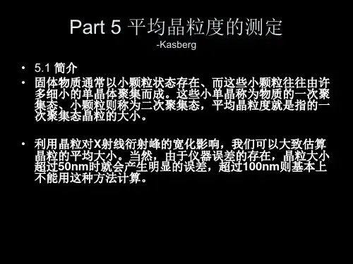
晶粒尺寸测定国标1、前言晶粒是晶体的组成单位,晶粒尺寸是影响晶体性质和性能的重要因素。
快速、准确测定晶粒尺寸的方法对于材料研究和生产具有重要的意义。
我国对于晶粒尺寸测定制定了一系列的国家标准,本文将通过对这些国标的介绍,来系统地了解晶粒尺寸测定的方法、准确性以及应用。
2、ASTM E112ASTM E112是国际上用于定义和描述晶粒结构的标准。
该标准规定了用金相显微镜测量晶粒尺寸的方法和程序。
测量过程中需要注意样品的制备,包括样品的制片和腐蚀处理,以便于清晰、准确地观察晶粒形貌。
该标准还规定了晶粒尺寸的测量方法,可以通过直接计数测量法、线交法、区域计数法等不同的方法来获得晶粒尺寸数据。
该标准对于金属材料、陶瓷材料等不同种类的材料都适用。
3、GB/T6394GB/T6394是我国用金相显微镜测量晶粒尺寸的国家标准。
该标准参考ASTM E112,规定了晶粒尺寸的测量程序和方法,包括样品的制备和观察、测量方法和设备以及数据的处理和统计。
该标准适用于金属材料和陶瓷材料等不同种类的材料。
该标准比ASTM E112多了一些内容,如样品的制片方法和显微镜的光源规范等。
4、GB/T6478GB/T6478是我国用电子后散射衍射(EBSP)法测量晶粒尺寸的国家标准。
该标准规定了EBSP法测量晶粒尺寸的方法和程序,包括样品的制备、显微镜的设置以及数据的处理和统计。
相比于金相显微镜法,EBSP法可以获得更为准确和精细的晶粒尺寸数据。
该方法适用于金属材料和半导体材料等不同种类的材料。
5、GB/T13320GB/T13320是我国用透射电子显微镜(TEM)法测量晶粒尺寸的国家标准。
该标准规定了TEM法测量晶粒尺寸的方法和程序,包括样品的制备、显微镜的设置以及数据的处理和统计。
相比于金相显微镜法和EBSP法,TEM法可以获得更高分辨率和更小的晶粒尺寸数据。
该方法适用于金属材料、陶瓷材料、半导体材料等不同种类的材料。
6、总结晶粒尺寸测定是材料科学和工程领域的重要内容之一。

名称:E112-96(2004年重新核准)——平均晶粒度标准测试方法1这一标准是根据E112条款颁布的;E112之后紧跟的数字表示最初编辑的年份,或者表示最后修改的年份(如果有修改),括号内数字(如果有的话)则表示最终批准的年份,上标ε1表示从最后修改或批准之日起的一次编辑更换。
该标准被国防部各相关部门认可使用。
简介这些金属平均晶粒度测试方法根本上是测量过程。
因为这一过程完全是独立于金属及其合金材料的几何学问题。
实际上,这些基本方法也应用于评估非金属的平均晶粒、晶体及晶胞尺寸。
如果材料组织结构接近于标准对比图谱中的某一个图的话,可以采用对比法。
截距法和求积法也经常应用于确定平均晶粒度。
然而,对比法不能应用于单个晶粒的测量。
1 范围1.1 本标准规定了金属组织的平均晶粒度表示及评定方法。
这些方法也适用晶粒形状与标准系列评级图相似的非金属材料。
这些方法主要适用于单相晶粒组织,但经具体规定后也适用于多相或多组元和试样中特定类型的晶粒平均尺寸的测量1.2 本标准使用晶粒面积、晶粒直径、截线长度的单峰分布来测定试样的平均晶粒度。
这些分布近似正态分布。
本标准的测定方法不适用于双峰分布的晶粒度。
双峰分布的晶粒度参见标准E1181。
测定分布在细小晶粒基体上个别非常粗大的晶粒的方法参见E930。
1.3本标准的测量方法仅适用平面晶粒度的测量,也就是试样截面显示出的二维晶度,不适用于试样三维晶粒,即立体晶粒尺寸的测量。
1.4 试验可采用与一系列标准晶粒度图谱进行对比的方法或者在简单模板上进行计数的方法。
利用半自动计数仪或者自动分析晶粒尺寸的软件的方法参见E1382。
1.5本标准仅作为推荐性试验方法,它不能确定受检材料是否接收或适合使用的范围。
1.6 测量数值应用SI单位表示。
等同的英寸-英镑数值,如需标出,应在括号中列出近似值.1.7 本标准没有列出所有的安全事项。
本标准的使用者应建立适合的安全健康的操作规范和使用局限性。
金属平均晶粒度测定方法1 范围1.1 本标准规定了金属组织的平均晶粒度表示及评定方法。
这些方法也适用晶粒形状与标准系列评级图相似的非金属材料。
这些方法主要适用于单相晶粒组织,但经具体规定后也适用于多相或多组元和试样中特定类型的晶粒平均尺寸的测量1.2 本标准使用晶粒面积、晶粒直径、截线长度的单峰分布来测定式样的平均晶粒度。
这些分布近似正态分布。
本标准的测定方法不适用于双峰分布的晶粒度。
双峰分布的晶粒度参见标准E1181。
测定分布在细小晶粒基体上个别非常粗大的晶粒的方法参见E930。
1.3本标准的测量方法仅适用平面晶粒度的测量,也就是试样截面显示出的二维晶度,不适用于试样三维晶粒,即立体晶粒尺寸的测量。
1.4 试验可采用与一系列标准晶粒度图谱进行对比的方法或者在简单模板上进行计数的方法。
利用半自动计数仪或者自动分析晶粒尺寸的软件的方法参见E1382。
1.5本标准仅作为推荐性试验方法,它不能确定受检材料是否接收或适合使用的范围。
1.6 测量数值应用SI单位表示。
等同的英寸-英镑数值,如需标出,应在括号中列出近似值.1.7 本标准没有列出所有的安全事项。
本标准的使用者英建立适合的安全健康的操作规范和使用局限性。
1.8 章节的顺序如下:2、参考文献2.1ASTM标准E3 金相试样的准备E7 金相学有关术语E407 微蚀金属和合金的操作E562计数法计算体积分数的方法E691 通过多个实验室比较决定测试方法的精确度的方法E883 反射光显微照相指南E930 截面上最大晶粒的评估方法(ALA晶粒尺寸)E1181双峰分布的晶粒度测试方法E1382 半自动或全自动图像分析平均晶粒度方法2.2 ASTM附件2.2.1 参见附录X23 术语3.1 定义-参照E73.2 本标准中特定术语的定义:3.2.1 ASTM晶粒度——G,通常定义为公式(1)N AE为100倍下一平方英寸(645.16mm2)面积内包含的晶粒个数,也等于1倍下一平方毫米面积内包含的晶粒个数,乘以15.5倍。
金属平均晶粒度测定方法1 范围1.1 本标准规定了金属组织的平均晶粒度表示及评定方法。
这些方法也适用晶粒形状与标准系列评级图相似的非金属材料。
这些方法主要适用于单相晶粒组织,但经具体规定后也适用于多相或多组元和试样中特定类型的晶粒平均尺寸的测量1.2 本标准使用晶粒面积、晶粒直径、截线长度的单峰分布来测定式样的平均晶粒度。
这些分布近似正态分布。
本标准的测定方法不适用于双峰分布的晶粒度。
双峰分布的晶粒度参见标准E1181。
测定分布在细小晶粒基体上个别非常粗大的晶粒的方法参见E930。
1.3本标准的测量方法仅适用平面晶粒度的测量,也就是试样截面显示出的二维晶度,不适用于试样三维晶粒,即立体晶粒尺寸的测量。
1.4 试验可采用与一系列标准晶粒度图谱进行对比的方法或者在简单模板上进行计数的方法。
利用半自动计数仪或者自动分析晶粒尺寸的软件的方法参见E1382。
1.5本标准仅作为推荐性试验方法,它不能确定受检材料是否接收或适合使用的范围。
1.6 测量数值应用SI单位表示。
等同的英寸-英镑数值,如需标出,应在括号中列出近似值.1.7 本标准没有列出所有的安全事项。
本标准的使用者应建立适合的安全健康的操作规范和使用局限性。
1.8 章节的顺序如下:2、参考文献2.1ASTM标准E3 金相试样的准备E7 金相学有关术语E407 微蚀金属和合金的操作E562计数法计算体积分数的方法E691 通过多个实验室比较决定测试方法的精确度的方法E883 反射光显微照相指南E930 截面上最大晶粒的评估方法(ALA晶粒尺寸)E1181双峰分布的晶粒度测试方法E1382 半自动或全自动图像分析平均晶粒度方法2.2 ASTM附件2.2.1 参见附录X23 术语3.1 定义-参照E73.2 本标准中特定术语的定义:3.2.1 ASTM晶粒度——G,通常定义为公式(1)N AE为100倍下一平方英寸(645.16mm2)面积内包含的晶粒个数,也等于1倍下一平方毫米面积内包含的晶粒个数,乘以15.5倍。
0前言晶粒度作为评价铝及铝合金材料的一个重要指标,对材料的力学性能、腐蚀性能等均有较大影响。
孟祥志等[1]研究发现,粗大晶粒是导致6061T4铝合金型材拉弯加工产生橘皮和裂纹的原因;徐磊等[2]发现,7A04铝合金锻件表面粗大晶粒会降低试样的疲劳性能;马小前等[3]研究发现,7A09铝合金铸锭粗大晶粒会导致成品挤压棒材晶粒粗大;王凤春等[4]研究发现,随着再结晶程度和晶粒尺寸的增大,7055铝合金板材晶间腐蚀性能降低。
对于晶粒度的测定,国内外均颁布了相关标准。
适用于铝合金晶粒度测定的现行有效标准有ASTM E112-13(2021)[5]、GB/T 6394—2017[6]、GB/T 3246.1—2012[7]、GB/T 3246.2—2012[8]等。
对以上4个标准从晶粒度的定义、半定量及定量的测定方法等方面进行对比分析,明确各标准之间的一致性、差异性以及存在的缺陷。
并针对在实际测定过程中遇到的问题,进行方法间对比探讨分析,保证晶粒度测定结果的准确性。
1标准对比分析1.1晶粒度的定义晶粒度定义为在多晶体金属中,排除孪生区和亚晶以外后的晶粒或晶体大小的量度尺寸[9-10]。
在现行标准中,使用平均晶粒截面的名义直径、Feret 直径,平均晶粒截面积、平均截距、平均直径,单位面积中的晶粒个数和单位体积中的晶粒个数等来描述晶粒的长度、面积和体积。
表示晶粒度的术语在不同的标准中有不同的表述,具体内容见表1。
表1不同标准中晶粒度的术语表述检测标准ASTM E112-13(2021)GB/T 6394—2017GB/T 3246.1—2012GB/T 3246.2—2012晶粒度的术语表述晶粒度级别数显微晶粒度级别数晶粒级别指数晶粒度1.2晶粒度半定量测定晶粒度的半定量测定采用图谱比较法,这也是铝合金晶粒度测定最常用的方法。
本文涉及的4个标准对于铝合金晶粒度测定的试样标准图谱信息见表2。
铝合金晶粒度测定方法探讨袁圣,张思平,辛荣,李政龙,陈小谦(西南铝业(集团)有限责任公司,重庆401326)摘要:通过对4个铝合金晶粒度测定标准进行对比分析,明确了各标准间的一致性和差异性。