微波实验系统说明书
- 格式:doc
- 大小:137.00 KB
- 文档页数:12
北京邮电大学电磁场与电磁波测量实验实验内容:微波测量系统的使用和波导波长与晶体检波器的校准测量学院:电子工程学院班级: 2014211202 执笔者:组员:2017年3月25日目录实验一微波测量系统的使用和信号源波长功率的测量 (1)1.实验内容 (1)1.1实验目的 (1)1.2实验原理 (1)1.3实验设备 (2)1.4实验步骤 (4)2.实验数据与分析 (6)2.1实验测量数据 (6)2.2理论分析 (6)2.3实验分析 (6)2.4误差分析 (7)3.实验心得与体会 (7)实验二波导波长的测量 (8)1.实验内容 (8)1.1【方法一】两点法 (8)1.2【方法二】间接法 (10)2.实验步骤 (11)2.1晶体检波率公式计算 (15)2.2误差分析 (15)2.3间接法测量波导波长 (16)3.思考题 (16)4.实验总结 (17)实验一微波测量系统的使用和信号源波长功率的测量1.实验内容1.1实验目的1.学习微波的基本知识;2.了解微波在波导中传播的特点,掌握微波基本测量技术;3.学习用微波作为观测手段来研究物理现象。
1.2实验原理测量微波传输系统中电磁场分布情况,测量驻波比、阻抗、调匹配等,是微波测量的重要工作,实验系统主要的工作原理如下图:1.3实验设备1.晶体检波器微波测量中,为指示波导(或同轴线)中电磁场强度的大小,是将它经过晶体二极管检波变成低频信号或直流电流,用电流电表的电流1来读数的。
从波导宽壁中点耦合出两宽壁间的感应电压,经微波二极管进行检波,调节其短路活塞位置,可使检波管处于微波的波腹点,以获得最高的检波效率。
2.波导管本实验所使用的波导管型号为BJ—100,其内腔尺寸为a=22.86mm,b=10.16mm。
其主模频率范围为8.20——12.50GHz,截止频率为6.557GHz。
3.隔离器位于磁场中的某些铁氧化体材料对于来自不同方向的电磁波有着不同吸收,经过适当调节,可使其对微波具有单方向传播的特性,隔离器常用于振荡器与负载之间,起隔离和单向传输的作用。


PXIe VNA PXIe-S5090• Frequency range: 300 kHz - 9 GHz• Wide output power adjustment range: -45 dBm to +13 dBm • Dynamic range: 138 dB (10 Hz IF bandwidth) typ.• Measurement time per point: 16 µs per point, min typ.• Up to 16 logical channels with 16 traces each max• Automation programming in LabVIEW, IVI drivers, IVI-C drivers, drivers • Time domain and gating conversion included• Frequency offset mode, including vector mixer calibration measurements• Up to 500,001 measurement points• Multiple precision calibration methods and automatic calibrationE X T E N D Y O U R R E A C H T MMeasurement Accuracy 3Impedance50 Ohm Test port connector 3.5 mm, femaleNumber of test ports 2Frequency range300 kHz to 9 GHzFull frequency accuracy ±5·10⁻⁶Frequency resolution1 Hz Number of measurement points2 to 500,001Measurement bandwidths (with 1/1.5/2/3/5/7 steps) 1 Hz to 1 MHz Dynamic range ²300 kHz to 1 MHz 123 dB (129 dB typ.)1 MHz to 5 MHz 133 dB (138 dB typ.)5 MHz to 6.5 GHz 138 dB (140 dB typ.)6.5 GHz to 8.0 GHz 133 dB (136 dB typ.)8 GHz to 9 GHz125 dB (130 dB typ.)Primary Specifications300 kHz to 9 GHzDirectivity 46 dB Source match 40 dB Load match 46 dB Reflection tracking ±0.10 dB Transmission tracking±0.08 dBEffective System DataTest Port Output300 kHz to 6.5 GHzDirectivity 15 dB Source match 15 dB Load match15 dB6.5 GHz to 9 GHzDirectivity 10 dB Source match 15 dB Load match15 dB Uncorrected System PerformanceNoise floor300 kHz to 1 MHz -120 dBm/Hz 1 MHz to 5 MHz -130 dBm/Hz 5 MHz to 6.5 GHz -135 dBm/Hz 6.5 GHz to 8.0 GHz -133 dBm/Hz 8.0 GHz to 9 GHz-130 dBm/Hz Damage level+26 dBm Damage DC voltage35 VTest Port Input[1] All specifications subject to change without notice. [2] The dynamic range is defined as the difference between the specified maximum power level and the specified noise floor. The specification applies at 10 Hz IF bandwidth. [3] Reflection and transmission measurement accuracy applies over the temperature range of (73 ± 9) °F or (23 ± 5) °C after 40 minutes of warming-up, with less than 1 °C deviation fromPortExt Trig Out Maximum output current 20 mA Output levelLow level voltage 0.0 to 0.6 V High level voltage3.0 to 3.8 V Polaritypositive or negative Connector typeSMB, maleTrigger OutputOperating system Windows 7 and aboveCPU frequency 1.0 GHz RAM512 MBPower supply+3.3 V 1.5 A +12 V1.5 ASystem & PowerRecommended factory adjustment interval3 YearsFactory AdjustmentOperating temperature +5 °C to +40 °C (41 °F to 104 °F)Storage temperature -50 °C to +70 °C (-58 °F to 158 °F)Humidity90 % at 25 °C (77 °F)Atmospheric pressure70.0 kPa to 106.7 kPaEnvironmental SpecificationsPortExt Trig In Input levelLow threshold voltage 1.1 V High threshold voltage2.6 V Input level range 0 V to + 5 V Pulse width ≥2 µsPolaritypositive or negativeInput impedance ≥2 kOhm Connector typeSMB, maleTrigger InputPortRef OUT 10 MHzInternal reference frequency10 MHz Output reference signal level at 50 Ohm impedance -1 dBm to 3 dBm Connector typeSMB, maleFrequency Reference OutputLength 221 mm Width 129 mm Height 20 mm Weight0.6 kg (21.2 oz)DimensionsPortRef IN 10 MHz External reference frequency 10 MHz Input level-3 dBm to 3 dBmInput impedance 50 Ohm Connector typeSMB, maleFrequency Reference InputMeasurement SpeedFrequency Range Number of pointsUncorrected 2-port calibration511.7 ms 3.2 ms 201 4.5 ms 8.8 ms 4017.8 ms 15.1 ms 160127.0 ms 53.7 ms 511.2 ms2.7 ms 2013.7 ms 7.4 ms 4016.8 ms 13.6 ms 160123.4 ms 46.5 ms 512.3 ms 4.3 ms 201 6.6 ms 13.3 ms 40112.0 ms 23.6 ms 160144.0 ms 87.7 ms 511.9 ms 3.9 ms 201 5.9 ms 11.7 ms 40111.1 ms 22.1 ms 160140.2 ms 80.4 ms 517.7 ms 15.1 ms 20128.0 ms 55.8 ms 40154.8 ms 109.2 ms 1601215.0 ms 430.0 ms 517.3 ms 14.7 ms 20127.2 ms 54.7 ms 40153.9 ms 107.8 ms 1601211.4 ms423.0 msfrom 300 kHz to 9 GHz IF bandwidth 100 kHz from 4 GHz to 5 GHz IF bandwidth 100 kHz from 300 kHz to 9 GHz IF bandwidth 10 kHz from 4 GHz to 5 GHz IF bandwidth 10 kHz 16 µs typ.200 µsfrom 4 GHz to 5 GHz IF bandwidth 1 MHz from 300 kHz to 9 GHz IF bandwidth 1 MHz Port switchover timeTime per pointTypical cycle time vs number of measurement points 7Extended Effective System Data300 kHz to 1 MHzDirectivity0.005Source match0.010Load match0.005Reflection tracking0.012Transmission tracking0.009Isolation (max noise level) 1.0·10⁻⁵Compression0.65·10⁻³1 MHz to 5 MHzDirectivity0.005Source match0.010Load match0.005Reflection tracking0.012Transmission tracking0.009Isolation (max noise level) 3.2·10⁻⁶Compression0.65·10⁻³5 MHz to 6.5 GHzDirectivity0.005Source match0.010Load match0.005Reflection tracking0.012Transmission tracking0.009Isolation (max noise level) 1.8·10⁻⁶Compression0.65·10⁻³6.5 GHz to 8.0 GHzDirectivity0.005Source match0.010Load match0.005Reflection tracking0.012Transmission tracking0.009Isolation (max noise level) 2.2·10⁻⁶Compression 1.15·10⁻³8 GHz to 9 GHzDirectivity0.005Source match0.010Load match0.005Reflection tracking0.012Transmission tracking0.009Isolation (max noise level) 3.2·10⁻⁶Compression 4.0·10⁻³Reflection Magnitude ErrorsSpecifications are based on isolating DUT (S 21 = S 12 = 0)Specifications are based on isolating DUT (S 21 = S 12 = 0)Reflection Phase ErrorsSpecifications are based on isolating DUT (S 21 = S 12 = 0)Transmission Magnitude ErrorsTransmission Magnitude ErrorsSpecifications are based on matched DUT, and IF bandwidth of 10 HzSpecifications are based on matched DUT, and IF bandwidth of 10 HzTransmission Phase ErrorsTransmission Phase ErrorsSpecifications are based on matched DUT, and IF bandwidth of 10 HzSpecifications are based on matched DUT, and IF bandwidth of 10 HzTransmission Phase ErrorsSpecifications are based on matched DUT, and IF bandwidth of 10 HzSpecifications are based on matched DUT, and IF bandwidth of 10 Hz。
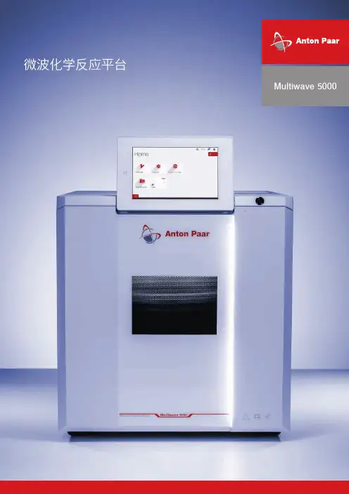
微波化学反应平台Multiwave 5000Product name精准的痕量元素分析从卓越的样品制备开始。
即使采用最佳分析设备,样品制备仍是获得可靠测量值的关键因素。
Multiwave 5000 的开发融入了 40 多年的样品制备经验,可满足当今实验室化学专家的需求。
作为迄今为止最简单易用的微波系统,它节省了实验室的时间和资金。
满足您需求的微波化学反应平台 由于采用灵活的平台概念,您可以将 Multiwave 5000 配置为最适合您应用的设备。
Multiwave 5000 提供:各种类型样品的消解(难度或体积不同) |酸浸提|微波溶剂萃取|蒸发|微波辅助氧燃烧| 紫外消解|样品干燥和合成| </1287>开始运行 - 甚至可以远程运行装入 转子选择方法一个系统,无限可能支持网络全球化拥有 >500 个预安装程序方法库操作便捷用户界面先进的您的样品可能很复杂 – 但它对 MULTIWAVE 5000 来说却很简单。
简便的反应罐操作无需工具无需工具即可完成消解罐的操作手动即可快速完成 Multiwave 5000 转子、消解罐和传感器的开启和密封。
这种无需工具的独特处理方法简化了频繁重复的工作步骤,节省了宝贵的时间。
在所有情况下确保最佳安全在高温高压下操作,安全问题极为重要。
为保护用户和设备, Multiwave 5000 配备多项主动和被动安全功能:自检、软件联锁和再密封安全门。
每台仪器都经过单独测试。
知识中心:获取仪器上的所有信息只需点击几下,所有相关信息都可以在仪器上找到:说明手册、大型方法库或应用指南等。
如果您在操作时有任何问题,您可以直接在 10.1 英寸的仪器屏幕上观看视频手册。
这些重要信息会随软件一起更新,可以免费获取,并通过推送通知告知。
用于制药行业Multiwave 5000 符合药典、GMP、GAMP 5 和 21 CFR Part 11 等国家和国际标准。

The LAC high-performance bench-top oven uses horizontal recirculating airflow to ensure uniform temperatures throughout the oven. A high-volume fan circulates air through perforated, stainless steel walls to create a constant horizontal airflow across all sections of the oven. The result is proven reliability in demanding production and laboratory applications such as curing, drying, sterilizing, aging and other process-critical procedures.Advanced control. Protocol 3™ is a microprocessor-based temperature and hi-limit controller with large LCD display and real time clock for auto start capability. The LCD display shows temperature readings along with clear, detailed information on oven status. Protocol 3™ features three operating modes for quick and easy operation: Manual mode, Timer mode and Profile mode. The data-logging functionality enables reporting and analyzing and data files can be exported via the controller’s USB port. Modbus RS485 com-munications are included for easy data access.Easy to clean and service. Cleaning is easy due to the scratch- resistant, baked enamel exterior, 304 stainless steel interior, and smooth door surface. Servicing is easy due to convenient top access to the heater and fan.Superior quality. The Despatch LAC features sturdy,welded, double-wall construction, three inches (7.6cm) of glass fiber insulation and heavy-duty gaskets. Each oven receives a thorough quality and performance test before it is shipped. Heating elements carry a five-year warranty. All models are UL/C-UL listed.FEATURES AT A GLANCEu F our sizes: 3.7 to 18 cu ft (105 to 510 liter)u M aximum temperature of 260˚C (500˚F)u H orizontal recirculating airflow u H igh limit over-temperature protection u P rotocol 3TM control with large LCD display,integrated data logging capabilities and USB port for simple oven set-up and data exportu P C interface for remote input, monitoring and recording (RS485 connection)u E nd-of-cycle and high-limit indicators u R obust type 304 stainless steel interiorF R E S H A I RHEATING ELEMENT FANEXHAUSTu L AC High-Performance OvenWith horizontal airflow for ultimate temperature uniformityThermal Processing TechnologyOPTIONSu D oor interlock switch turns off heaterand fan when door is openedu C hart recordersu F orced exhaust for faster moistureremoval (not Class A)u D oor with window and interior lightoperating temperature and cooling times are based on 20°C ambient temperature measured at the fresh air inlet. Specifications are subject to change without notice. If the existing specifications differ from yours, ask about our customizing capabilities.u 2” access port for test wires u O ven standu R einforced shelves 200lb (91Kg) capacity u C E compliance u E lectric door locku 208V full performance packageWarning: Despatch LAC Ovens (without Class A option) arenot to be used with flammable solvents, combustible materi-als or enclosed containers. If your process involves flammable solvents, consult the factory about modifications.Model LFC1-38 (240 volt) is available for Class A operation.© 2016 ITW EAE, a division on Illinois Tool Works. All rights reserved. Despatch is a registered trademark in the U.S. and other countries. LAC 11-168860 207th Street West Minneapolis, MN 55044 USAGLOBAL HEADQUARTERSmain phone: 1-800-726-0110international/main: 1-952-469-5424 sales: 1-800-726-0550international/sales: 1-952-469-8240******************SERVICE AND TECHNICAL SUPPORTservice parts: 1-800-473-7373international service/main: 1-952-469-8230 service fax: 1-952-469-8193**************************************Thermal Processing Technology。
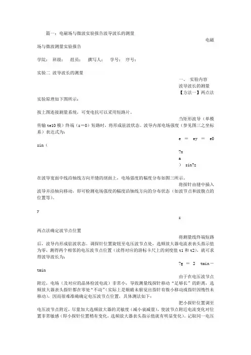
篇一:电磁场与微波实验报告波导波长的测量电磁场与微波测量实验报告学院:班级:组员:撰写人:学号:序号:实验二波导波长的测量一、实验内容波导波长的测量【方法一】两点法实验原理如下图所示:按上图连接测量系统,可变电抗可以采用短路片。
当矩形波导(单模传输te10模)终端(z=0)短路时,将形成驻波状态。
波导内部电场强度(参见图三之坐标系)表达式为:e =ey =e0 sin(?xa) sin?z在波导宽面中线沿轴线方向开缝的剖面上,电场强度的幅度分布如图三所示。
将探针由缝中插入波导并沿轴向移动,即可检测电场强度的幅度沿轴线方向的分布状态(如波节点和波腹点的位置等)。
yz两点法确定波节点位置将测量线终端短路后,波导内形成驻波状态。
调探针位置旋钮至电压波节点处,选频放大器电流表表头指示值为零,测得两个相邻的电压波节点位置(读得对应的游标卡尺上的刻度值t1和t2),就可求得波导波长为:?g = 2 tmin-tmin由于在电压波节点附近,电场(及对应的晶体检波电流)非常小,导致测量线探针移动“足够长”的距离,选频放大器表头指针都在零处“不动”(实际上是眼睛未察觉出指针有微小移动或指针因惰性未移动),因而很难准确确定电压波节点位置,具体测法如下:把小探针位置调至电压波节点附近,尽量加大选频放大器的灵敏度(减小衰减量),使波节点附近电流变化对位置非常敏感(即小探针位置稍有变化,选频放大器表头指示值就有明显变化)。
记取同一电压波节点两侧电流值相同时小探针所处的两个不同位置,则其平均值即为理论节点位置:1tmin = ? t1 ? t2 ?2最后可得?g = 2 tmin- tmin (参见图四)【方法二】间接法矩形波导中的h10波,自由波长λ0和波导波长?g满足公式:?g =???? 1 ? ? ??2a?2其中:?g=3?108/f,a=2.286cm通过实验测出波长,然后利用仪器提供的对照表确定波的频率,利用公式cλ0=确定出λ0,再计算出波导波长?g。
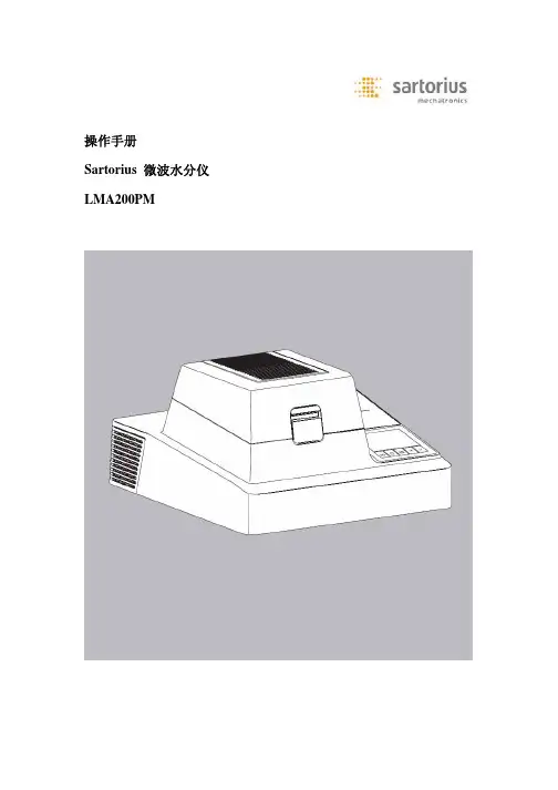
操作手册Sartorius 微波水分仪LMA200PM使用目的LMA200PM实验室水分测定仪是专门为水分含量在8%——100%的水溶液做快速水分分析而设计的。
使用玻璃纤维膜制的样品盘,用微波技术均匀加热样品而使水分蒸发。
分布均匀的微波能快速干燥,分析时间约40——120秒。
样品的水分含量通过计算由内置称重系统测得的样品加热前后的重量差而得到。
内置,低噪音的热敏打印机根据用户自定义GLP兼容的打印输出模式来记录分析结果。
LMA200PM尤其耐用且容易操作。
内容2使用目的3安全预警3仪器的整体结构图4使用入门6操作设计9设置16设置菜单下的参数18操作24数据输出功能26 数据界面28 保存数据28 故障分析29 维护30 技术参数30 附件32 机型尺寸安全预警安全信息注释:操作LMA200PM前务必仔细阅读操作说明书。
不正确的使用及操作会损坏仪器。
LMA200PM只能由专业人员安装、操作。
同时也要了解当地的国家相关法律,标准,规则,指导以及环境保护条文。
所有操作该仪器的人员都必须了解该安全预警。
警告LMA200PM的重量约22kg。
运输和安装过程中需要两个人搬动。
遵循安全规则操作。
移动LMA200PM前必须断开电源。
在稳定,水平,光滑的表面上安装LMA200PM。
不要在户外操作LMA200PM,也不要在有危险物的地方操作。
化学品包括气体和灰尘会腐蚀水分仪的外形和电缆。
LMA200PM不要暴露在强电磁场中(例如,靠近高压电线的地方),不能将其安装在靠近有磁场物质的地方。
不能将其安装在易燃易爆物体的附近。
不能将其暴露在腐蚀性化学气体或高温、高水分、高振动的环境中。
参考“技术参数”中的重要技术数据。
保证安装地点具有足够空间来散发实验产生的热。
仪器和墙之间至少间隔20厘米,与顶墙至少留有1米的距离。
保证冷却风扇能一直正常运行,若风扇有故障请立即关闭仪器并专业人士维修。
如果使用由别的厂家制造的电缆,必须先检查电缆的pin 分配图,若分配图与sartorius的不同请立即断开连接。

第一章前言1.1 项目背景微波炉作为一种新型的厨具。
它采用电磁感应电流(又称涡流)的加热原理打破了传统的明火烹调方式,微波炉的交变磁场是通过电子线路板组成部分来产生、当用含铁质锅具底部放置炉面时,锅具即切割交变磁力线的交变的电流(即涡流)在锅具底部金属部分产生,电磁感应电流使锅具铁分子无规则高速运动,其热能是因为分子相互碰撞、摩擦产生(故微波炉煮食的热源来自于锅具底部而不是微波炉本身发热传导给锅具,所以热效率要比所有饮具的效率均高出近1倍)来实现器具本身自行高速发热,用来加热和烹饪食物,从而达到煮食的目地。
1.2微波炉简介1.2.1微波炉的基本工作原理微波炉主要由交流进线电路、电源电路、LC振荡电路、功率控制电路、整流电路、EMC防护电路、滤波电路、同步电路、控制及显示电路、电压检测电路、锅具检测电路、过零检测电路、电流检测电路、主控CPU电路、高低压保护电路、IGBT模块等组成。
图1.1为微波炉的工作原理框图图1.1微波炉的工作原理框图1.2.2微波炉的基本组成1.加热部分:微波炉有搁板在锅体下面,也有励磁线圈。
对锅体进行加热是根据电磁感应产生涡电流。
2.控制部分:主要有电源开关,功率选择钮,温度调节按钮等。
由内部的控制电路来控制。
3.冷却部分:采用风冷的方式。
炉身的侧面有进风口和出风口,内部有风扇。
4.电气部分:由整流电路、逆变电路、控制回路、继电器、电风扇等组成。
5.烹饪部分:主要包括各种炊具,供用户使用。
1.2.3微波炉的优缺点微波炉作为一种新型的厨具,具有以下优点。
1.高效节能:微波炉降低了损耗,是因为其使锅具自身发热,大大提高了热效率,热效率可达到85%~99%,与传统加热方式不同,与电炉、液化气炉等炉具相比,节省了大量的能源。
如图1.2所示2.智能烹饪:智能控制是利用单片机进行,无须看管,具有定时预约功能,来实现自动烹饪的功能。
3.安全可靠:通过了国家安全验证,使用安全可靠。
4.环保卫生:锅具可实现自身发热,不会产生热辐射,并且不排放烟尘和一氧化碳等废气,使烹饪环境更加环保卫生。

3B SCIENTIFIC® PHYSICS1009950 (10,5 GHz, 115 V, 50/60 Hz)1009951 ( 9,4 GHz, 230 V, 50/60 Hz)Bedienungsanleitung09/17 ERL/ALFBetriebsgerät1 Anschluss für Empfänger2 Verstärkerausgang3 Verstärkerausgang (Masse)4 Anschluss für Sender5 Modulationseingang (Masse)6 Modulationseingang7 Wahlschalter für Modulation(intern/off/extern),8 Schalter für internen Laut-sprecher9 Regler für SignalverstärkungEmpfänger10 Buchse für Steckernetzgerät12 V AC (Gehäuserückseite)Zubehör11 Sender mit Hornantenne12 Auflageplatte für Prisma13 Prisma aus Paraffin14 Reflektorplatte15 Abdeckplatte für Doppelspalt16 Platte mit Doppelspalt17 Absorptionsplatte18 Polarisationsgitter19 Empfänger mit Hornantenne20 Mikrowellenbank21 Mikrowellensonde22 Mikrowellen-Gelenkbank mitPlattenhalterHF-Felder können in biologisches Gewebe ein-dringen und dieses erwärmen. Der enthaltene Mikrowellensender ist so leistungsschwach, dass Gefährdungen bei sachgemäßem Betrieb des Gerätes nicht auftreten.Bei bestimmungsmäßigem Gebrauch ist der si-chere Betrieb des Gerätes gewährleistet. Die Sicherheit ist jedoch nicht garantiert, wenn das Gerät unsachgemäß bedient oder unachtsam behandelt wird.∙Vor Inbetriebnahme sind Gehäuse und Netzleitung auf Beschädigungen zu über-prüfen.∙Wenn anzunehmen ist, dass ein gefahrlo-ser Betrieb nicht mehr möglich ist (z.B. beisichtbaren Schäden), ist das Gerät unver-züglich außer Betrieb zu setzen.∙Der Anschluss des Senders ist nur an das 3B-ELWE Betriebsgerät zulässig.∙In Schulen und Ausbildungseinrichtungen ist der Betrieb des Gerätes durch geschul-tes Personal verantwortlich zu überwachen. ∙Direktes Hineinblicken in den Antennen-trichter des Senders sowie in das reflek-tierte Strahlenbündel ist zu vermeiden.∙Gerät nur durch eine Fachkraft öffnen las-sen.Mit dem Gerätesatz können Mikrowellen er-zeugt und empfangen werden.Mit den enthaltenen Komponenten und Geräten sind vielfältige Experimente möglich, die sowohl qualitative als auch quantitative Aussagen er-möglichen.Das vom Sender ausgesandte und eng be-grenzte Bündel elektromagnetischer Wellen im cm-Bereich kann mit der Hornantenne (19) oder der Sonde (21) empfangen werden. Die Modu-lation des Empfängersignals kann über den in-ternen Lautsprecher hörbar gemacht werden, wobei die Intensität des akustischen Signals mit der Stärke des empfangenen Signals zu- oder abnimmt.Das Mikrowellengerät wird über ein Stecker-netzgerät 12 V AC gespeist.Das Mikrowellengerät 10,5 GHz (1009950) ist für eine Netzspannung von 115 V (±10 %) aus-gelegt, das Gerät 9,4 GHz (1009951) für 230 V (±10 %).1 Betriebsgerät1 Sender mit Hornantenne1 Empfänger mit Hornantenne1 Mikrowellensonde1 Mikrowellenbank, 800 mm1 Mikrowellen-Gelenkbank, 400 mm mit Plat-tenhalter1 Reflektorplatte 180 x 180 mm²1 Polarisationsgitter, 180 x 180 mm²1 Absorptionsplatte aus Faserstoff, 180 x 180mm²1 Prisma aus Paraffin1 Auflageplatte für Prisma1 Platte mit Doppelspalt1 Abdeckplatte für Doppelspalt1 BedienungsanleitungSender mit Hornantenne:Frequenz des Oszillators: 9,4 GHz (1009951)10,5 GHz (1009950)Sendeleistung: 10 mW bis 25 mW Modulationsart: AM Modulationssignal: über WahlschalterIntern /aus /extern Modulation intern: ca. 3 kHzca. 80 % AM Modulation extern: 100 Hz bis 20 kHzmax. 1 V Akustisches Signal: intern (schaltbar) Ausgangsspannung: max. 10 V Akustisches Signal: intern (schaltbar) Ausgangsspannung: max. 10 VEmpfänger mitHornantenne: Siliziumdiode mitResonator Mikrowellensonde: Siliziumdiode mitResonator Versorgungsspannung: 12 V AC über Ste-ckernetzgerät AbmessungenBetriebsgerät: 170 x 200 x 75 mm³5.1 Aufbau Schienensystem (Grundeinstel-lung)∙Zentrische Schraube unter der Skalen-scheibe in die Bohrung der langen Schiene einsetzen.Ausgangslage ist ein gestrecktes Schienensys-tem (Pfeil auf der langen Schiene weist auf …0°“ der Winkelskala).∙Gelenkfuß durch Schieben an der Zeiger-spitze auf Skalennullpunkt einstellen.Die Zeigerspitze weist in die Lotrichtung des Plattenhalters und ermöglicht somit das direkte Ablesen oder Einstellen des Einfallswinkels (Ablesung an der äußeren Ziffernskala). 5.2 Systemaufbau∙Netzanschluss herstellen.∙Empfänger mit Hornantenne bzw. Empfän-gersonde an Anschluss für Empfänger (1) an-schließen.∙Sender mit Hornantenne an Anschluss für Sender (4) anschließen.∙Sender und Empfänger entsprechend den Abbildungen zu den Experimenten auf Schienensystem anordnen.∙Lautstärke mit Regler für Signalverstärkung(9) auf mittlere Position stellen.∙Lautsprecher mit Schalter (8) einschalten. ∙Modulator mit Schalter (7) auf …INT“ schal-ten.Das abgestrahlte Mikrowellensignal wird recht-eckförmig moduliert, die Modulationsfrequenz kann über den eingebauten Lautsprecher hör-bar gemacht werden.An den Buchsen (2) und (3) kann das verstärkte Signal des Empfängers als Gleichspannung (nach abgeschalteter Modulation), als Recht-eckspannung (bei interner Modulation) oder als NF-Signal (durch externe Modulation) abgegrif-fen werden.Die Modulation ist mit der Mittelstellung des Schalters (7) deaktiviert. Am Buchsenpaar (3)(4) liegt eine, dem Pegel und der Verstär-kung proportionale Gleichspannung, die z.B. über ein Zeigerinstrument (z.B. Analogmultime-ter Escola 30 1013526) angezeigt werden kann. Wird mit Schalter (7) die Stellung …EXT“ ge-wählt, so können NF-Signale (z.B. von einem MP3 Player) über die Buchsen (5) und (6) ein-gekoppelt und über den internen Lautsprecher im Basisgerät wiedergegeben werden. (Adapter Klinkenstecker auf 4-mm Buchse erforderlich). Die Informationsübertragung erfolgt hierbei über das Mikrowellensignal zwischen Sender und Empfänger.(19) einander senk-Maximaler Empfang, wenn Öffnungen direkt ge-geradlinig aus (in homogenem Medium und auch im Va-(elektri-scher Isolator) zwischen Sender und Emp-Verstärkung (9) im mittleren Bereich einstel-Isolato-und einspannen Verstärkung im unteren Bereich einstellen.Mikro-da kein Empfangssig-angefeuchtete AbsorptionsplatteFolgerung: Beim Durchdringen von Stoffen mit ab-Reflektorplatte im Winkel von ca. 30°, 40°, einstellen; Winkel der langen Schiene ändern, bis ma-durchführen Folgerung: An elektrischen Leitern werden Mik-rowellen reflektiert. Das Reflexionsgesetz wirdcmgegenüberstellen Gesendete und reflektierte Welle überlagern(Markierungoben)Minima (Knoten) oder Maxima (Bäuche) bestim-/2).Frequenz≈6.6 BrechungGrundeinstellung vornehmen (5.1).Auflageplatte für Prisma (12) in die dem Prisma (13) auf Auflageplatte legen und Lange Schiene axial drehen, bis maxima-Folgerung: Mikrowellen durchdringen Paraf-fin. Beim Übergang der Welle von Luft in Pa-derende-Sender (11) ca. 20 cm vom Plattenhalter entfernt und Empfänger (19) in einem Ab-Plattenhaltereiner Kreisbahn so weit aus Wellenbündel her-aus bewegen, bis das Signal deutlich ab-Einfachspalt in den Plattenhalter einset-auf Folgerung: Die Mikrowelle wird am Spalt ge-dem Spalt wieder nachweisbar (hörbare Zunahmeder Sender ca. 20 cm vor der Metallplatte an-Platteabgeschattetendenabge-Platte mit Doppelspalt (16) im Plattenhal-Sender ca. 12 cm vor der Platte positio-Abstandzuauftretenden Maxima die Anzahl der Spalte übersteigt, istPlattenhalterhorizontalerPolarisationsgitters Empfangsmöglichkeit bei vertikaler Aus-richtung des Polarisationsgitters überprü-Folgerung: Da einmal ein Empfang nachge-kein Signal den Empfänger erreicht, wird demons-triert, dass die Hornantenne ein Wechselfeld erzeugt, das nur in einer Richtung schwingt, Mit dem Experiment wird der Nachweis einerWerden Sender und Empfänger gegeneinan-der horizontal und vertikal ausgerichtet, so istin den Strahlengang eingebracht und in der dar-ein abgeschwächtes Signal empfangen. Die Po-Sender und Empfänger einander gegen-Empfänger außerhalb der Schiene senk-Maximaler Empfang, wenn Öffnungen di-An Hand der internen Modulation (3 kHz Sig-nal) oder der externen Modulation (z.B. Ton-signal eines MP3 Players) kann InformationFolgerung: Mikrowellen (elektromagnetischedie-3B Scientific GmbH ▪ Ludwig-Erhard-Str. 20 ▪ 20459 Hamburg ▪ Deutschland ▪ 。
(完整)微波基本参数测量实验报告微波基本参数测量实验报告【引言】微波是指频率为300MHz-300GHz的电磁波,是无线电波中一个有限频带的简称,即波长在1米(不含1米)到1毫米之间的电磁波,微波的基本性质通常呈现为穿透、反射、吸收三个特性。
微波成为一门技术科学,开始于20世纪30年代。
微波技术的形成以波导管的实际应用为其标志,若干形式的微波电子管(速调管、磁控管、行波管等)的发明,是另一标志。
在第二次世界大战中,微波技术得到飞跃发展。
因战争需要,微波研究的焦点集中在雷达方面,由此而带动了微波元件和器件、高功率微波管、微波电路和微波测量等技术的研究和发展。
至今,微波技术已成为一门无论在理论和技术上都相当成熟的学科,又是不断向纵深发展的学科。
【实验设计】一、实验原理1、微波微波是指频率为300MHz-300GHz的电磁波,是无线电波中一个有限频带的简称,即波长在1米(不含1米)到1毫米之间的电磁波,是分米波、厘米波、毫米波的统称。
微波频率比一般的无线电波频率高,通常也称为“超高频电磁波”。
微波作为一种电磁波也具有波粒二象性。
微波的基本性质通常呈现为穿透、反射、吸收三个特性。
对于玻璃、塑料和瓷器,微波几乎是穿越而不被吸收。
对于水和食物等就会吸收微波而使自身发热,微波炉就是利用这一特点制成的,而对金属类东西,则会反射微波。
2、微波的似声似光性微波波长很短,比地球上的一般物体(如飞机,舰船,汽车建筑物等)尺寸相对要小得多。
使得微波的特点与几何光学相似,即所谓的似光性。
因此使用微波工作,能使电路元件尺寸减小,使系统更加紧凑;可以制成体积小,波束窄方向性很强,增益很高的天线系统,接受来自地面或空间各种物体反射回来的微弱信号,从而确定物体方位和距离,分析目标特征。
由于微波波长与物体(实验室中无线设备)的尺寸有相同的量级,使得微波的特点又与声波相似,即所谓的似声性。
3、波导管波导管是一种空心的、内壁十分光洁的金属导管或内敷金属的管子。
© Biotage 2020Microwave SynthesisFourth Generation Systems2Microwave Synthesis – Fourth Generation Systems© Biotage 2020Speeding up reactions has never been easier. Biotage microwave synthesizers are the first-choice tools for organic chemists who need to accelerate their production of new compounds.Diverse Exploration and Fast ResultsA Common Goal for Modern Chemistry LabsCONTENTS2 Diverse Exploration and Fast Results3 Microwave Vials4 Biotage ® Initiator+6 Biotage ®Initiator Robot Eight & Robot Sixty 7 Ordering InformationMicrowave heating is by far the superior choice for synthesizingnovel compounds and can offer advantages other than just speed. Working at temperatures and pressures not attainable through traditional heating, it allows chemists to perform reactions previously not possible.Discover the Advantages of Microwave SynthesisWhy Wait Hours, or Even Days, for Results?Simply by increasing temperature, microwave synthesis can complete reactions up to a thousand times faster than traditional reflux conditions.Why Limit the Range of Experiments?Quickly test your creative synthetic ideas and rapidly synthesize compounds of interest to fill gaps in your structure activity relationship (SAR). Reduce the iterative SAR cycle-time and increase productivity for the entire project team.Don’t Waste Time Supervising the Synthesis ProcessBiotage microwave systems are predictable, reliable and safe. Each instrument has precise control of time, temperature and pressure to ensure that methods are reproducible and easily transferred or scaled up. Systems are also available with reliable automation and will run an entire sequence without manual intervention.Will the Microwave Fit Into Your Process, Hood Space and Budget?Chemical synthesis has never been easier. Simply put the reaction mixture into the vial, cap it, insert the vial into the microwave, key in the reaction parameter, and run. The latest generation of microwave synthesis systems are compact,easy to use and very affordable.Introduction3Microwave VialsHigh Precision Glass VialsDurable and safe reactions at all times. Our highprecision microwave vials are designed and tested to withstand pressures beyond 30 bar in a wide range of conditions.Simplicity is one of the benefits of modern microwave equip-ment. Reactions are performed in glass vials sealed with caps and heated in the microwave cavity.Magnetic Stir BarsThe reaction mixture is continuously blended by magnetic stirring promoting homogenous heating throughout.Optimum Vial SizesMigrate directly to multi-gram scale without re-optimization* using the 10–20 mL vials. These larger vials can also be used for preparation of scaffolds and intermediates or for generating larger quantities of active compounds for testing.Each Biotage microwave vial has been designed for safe and efficient heating within its specified volume range. Together, the four vial types provide full scalability within the volume range 0.2–20 mL. Methods that are run at a lower volume are directly transferrable across the entire volume range of 0.2–20 mL.Features and Advantages»Reseal™ design allows the septum to beresealed after it has been penetrated for repeated additions of reagents or in-situ sampling.»Manufactured from contaminantfree microwave-safe glass.»Magnetic stirring promotes homogenoustemperature distribution.»Available sizes: 0.2–0.5 mL, 0.5–2.0 mL,2.0–5.0 mL and 10–20 mL.Biotage’s microwave vials are available in four sizes: 0.2–0.5 mL; 0.5–2.0 mL; 2.0–5.0 mL and 10–20 mL.*Biotage Microwave Vials 10–20 mL, cannot be used with temperatures above 250 °C and/or pressures above 20 bar.4Microwave Synthesis – Fourth Generation Systems© Biotage 2020Results can be emailed directly to the user after a run, ordownloaded through the USB port at the front of the instrument.FlexibleControlled temperatures and pressures up to 300 °C and 30 bar open new possibilities to complete difficult reactions. Even low boiling point solvents can now be run at higher temperatures. The system automatically senses and performs reactions at their highest possible temperatures.The Initiator+ supports all Biotage vials from 0.2 to 20 mL,delivering greater flexibility and direct scale-up from milligrams to grams. The four different vial sizes can be used in any order or combination without system modifications.The single-mode applicator and the Dynamic Field Tuning™ features offer faster and more powerful heating (400 W) of a broader range of solvents. The setting for low microwave absorbing solvents enhances the heating for e.g. toluene and 1, 4-dioxane.Press the large touch-screen and heat your organic reagents to 300 °C in just a few seconds. TheInitiator+ does just that, and adds intelligent features that make innovation fast, reliable and safe.The Biotage Initiator+ represents a new generation of synthe-sizer instruments for organic, medicinal, materials, nano and polymer chemistry professionals. It is an upgradeable and reliable platform allowing chemists to make great discoveries in less time.Easy to OperateInitiator+ facilitates the transition from traditional methods to microwave enhanced techniques. Learning microwave synthesis is fast and pleasant with the Initiator+. The large touch screen display makes the experience user friendly from set-up toresults. The built-in wizard guides the user through experiment set-up step by step and helps converting conventional condi-tions to microwave synthesis parameters.Biotage ®Initiator+Fourth Generation Microwave SynthesizerLargest screen on the market, with intuitive user interface and touch control.High grade aluminum casing for maximum robustness.Additional communications ports allows for remote control and monitoring.The reaction vessel is secured with a triple-tier safety lock to ensure maximum operator safety at all times.Easy access cover enables quick maintenance.USB port for quick transfer of results and methods.UpgradableEach compound synthesis has unique demands. A rangeof accessories are available to increase automation for higher throughput.Connecting the SP Wave module and the Robot Eight kit will transform this instrument into a microwave assisted peptide synthesizer, extending the scope of discoveries beyond small molecules.The novel vortex mixing unit ensures gentle but thorough homogeneous heat distribution. With the optional fiber optic probe, reaction temperature can be monitored inside the vial for even better visibility.Best-in-Class SafetyIn the early days of microwave synthesis, bursting vials were a menace. All Biotage microwave synthesizers are designed with a triple-tier safety lock for safe operation at elevated temperatures and pressures.Features and Advantages»300 °C controlled reaction temperature »30 bar controlled reaction pressure»Large 10” touchscreen»Modular automation solutions»Guided step-by-step wizard»In situ temperature measurement»Upgradable to run peptide synthesis»Safe and simple»Utilizes all Biotage vials, from 0.2 to 20 mL »Remote monitoringAccessories»Modules for automation (p. 6)»Vials (p. 3)»Peptide liquid handlersSpecificationsHeating ProcessTemperature range40–300 °CHeating rate Typically 2–5 °C/s depending on solventand power appliedReaction time Up to 96 hours. Typically, most reactionsrequire 2–15 minutes of irradiation.Pressure range0–30 bar (3 MPa; 435 psi)Power range0–400 W from magnetron at 2.45 GHzReaction volumes0.2–20 mLAgitation Variable magnetic stirrer (300–900 RPM)UpgradesUpgradable with Robot Eight and Robot SixtyProcessing capacity8 or 60 vials (with robot upgrade)Rack capacity 2 x 2 or 2 x 12 vials (large); 2 x 4 or 2 x30 vials (small)Technical specs.Electrical supply100–240V~, 50/60HzMax. power consumed1100 VACooling Pressurized air supply: >60 L/min (2.1cubic feet/min), 2.5–4.0 bar (0.25–0.40MPa; 36–58 psi)Weight21 kg (46.2 lbs)Dimensions (WxDxH)365 x 422 x 421 mm (14.4”x 16.6” x 16.6”)Max sound level70 dB(A)InterfacesTouch screen10.4”Ethernet LAN Complies with IEEE 802.3 (ANSI 8802-3)USB USB 3.0Archiving/back-up Via USBPrinting Via LANCertifications CE, CSA certified56Microwave Synthesis – Fourth Generation Systems© Biotage 2020The Initiator+ can be upgraded from a single-sample manual format to an automated 8- or 60-position system. The modular design allows a user to add on different automated sample processors dependent on throughput requirements.The 8-position sample bed gives the user a compact auto m ation solution to start scale-up process and library build-up. The 8-position system is useful in a multi-userenvironment or for queuing multiple reactions. Flexible opera-tion enables the use of both large and small vials in combina-tion at any time and in any order without manual intervention.The 60-position sample bed supports the production of focused libraries, multi-user environments and scale-out,and use of both large and small vials in any order without manual intervention.Biotage ®Initiator Robot Eight & Robot SixtyIntelligent AutomationSpecificationsSample processor Robot Eight/Robot Sixty Processing capacity 8 vials/60 vials Rack capacity (large) 2x2 vials/2x12 vials Rack capacity (small) 2x4 vials/2x30 vialsVial sizes0.2–0.5; 0.5–2; 2–5; 10–20 mL,Operating temperature 18–32 °C Storage temperature -25 °C to 60 °CHumidity 20–95% at room temperature Electrical supply Supplied by Initiator CertificationsCE, CSA certifiedWeight & Dimensions (WxDxH)Initiator+ Eight 28 kg (61.7 lbs)Initiator+ Sixty 34 kg (75 lbs)Initiator+ Eight 400 x 500 x 580 mm (15.7" x 19.7" x 22.8")Initiator+ Sixty625 x 422 x 470 mm (24.6" x 16.6" x 18.5")Ordering InformationProduct Part number InstrumentsInitiator+ Microwave System356700 Initiator+ Microwave Systemwith Robot Eight356702Initiator+ Microwave Systemwith Robot Sixty356703RobotsRobot Eight355380 Robot Sixty355381 Microwave Vials0.2–0.5 mL, qty. 100 3554580.2–0.5 mL, qty. 300 3556270.2–0.5 mL, qty. 500 3556280.5–2 mL, qty. 100 3520160.5–2 mL, qty. 300 3546250.5–2 mL, qty. 500 3556292–5 mL, qty. 100 3515212–5 mL, qty. 300 3546242–5 mL, qty. 500 35563010–20 mL, qty. 50 35483310–20 mL, qty. 100 35563110–20 mL, qty. 250 355632 Microwave vial caps and stir bars are included with vial orderOrdering informationProduct Part number AccessoriesSP Wave Module356013Vial caps included reseal septa, qty. 100 352298Manual cap crimper 353671Manual cap remover 353913Vial adapter 0.2–0.5 mL, qty. 10 355459Vial adapter 10–20 mL, qty. 12 355367O-rings 10–20 mL adapter, qty. 10 354838Vial rack Initiator 8, holds (4) 0.2–5 mL vials 355391Vial rack Initiator 8, holds (2) 10–20 mL vials 355390Vial rack Initiator 60, holds (30) 0.2–5 mL vials 353478Vial rack Initiator 60, holds (12) 10–20 mL vials 354798Stir bars 0.2–0.5 mL, qty. 25 355545Stir bars 0.5–2 mL, qty. 25 355544Stir bars 2–5 mL, qty. 25 355543Stir bars 10–20 mL, qty. 5 353930Waste Tray355366Biotage® Initiator+ SP WaveFurther UpgradingUpgrade from anInitiator+ by connectingthe SPWave peptidesynthesis module andthe Robot Eight kit toperform microwaveassisted peptidesynthesis with vortexmixing.For more information, please refer to the Peptide SynthesisWorkflow brochure (PPS446), available at .7© Biotage 2020Your Complete Partner forEffective ChemistryBiotage is a worldwide supplier ofinstruments and accessories designed to facilitate the work of laboratory chemists. With our deep knowledge of the industry, academic contacts and in-house R&D teams, we can deliver the best solutions to your challenges. We take great pride in our flexibility and ability to meet our customer’s individual needs. With strong foundations in both analytical and organic chemistry, we can offer the widest range of solutions available on the market.Literature Number: PPS299.v5© 2020 Biotage. All rights reserved. No material may be reproduced or published without the written permission of Biotage. Information in this document is subject to change without notice and does not represent any commitment from Biotage. E&OE. A list of all trademarks owned by Biotage AB is available at /legal. Other product and company names mentioned herein may be trademarks or registered trademarks and/or service marks of their respective owners, and are used only for explanation and to the owners’ benefit, without intent to infringe.EUROPEMain Office: +46 18 565900Fax: +46 18 591922Order Tel: +46 18 565710Order Fax: +46 18 565705*****************Support Tel: +46 18 56 59 11Support Fax: + 46 18 56 57 11*****************************NORTH & LATIN AMERICA Main Office: +1 704 654 4900Toll Free: +1 800 446 4752Fax: +1 704 654 4917Order Tel: +1 800 446 4752Order Fax: +1 704 654 4917************************Support Tel: +1 800 446 4752*****************************JAPANTel: +81 3 5627 3123Fax: +81 3 5627 3121*************************************************CHINATel: +86 21 68162810Fax: +86 21 68162829*************************************************KOREATel: +82 31 706 8500Fax: +82 31 706 8510***************************************************INDIATel: +91 11 45653772 *****************Distributors in other regions are listed on 。
FACT SHEET - TS50, QMS-C-AS-021-02, 11-2020 © MPI Corporation 2020 - Data subject to change without further notice.RF Calibration• Auxiliary chuck for calibration substrates • Built-in ceramic for accurate calibration•1 µm flatness for consistent contact qualityModular Chucks• Non-thermal chucks• Supports DC/CV and RF applicationsDC and RF Positioners• Supports 2-port RF and up to 6 DC positioners • Wide range of positioners available•Dedicated probe arms for DC/CV and RF measurementsChuck XY-Theta Stage Movement• 100 x 75 mm XY movement• Including 25 x 25 mm fine micrometer control • ±5° Theta fine adjustment • Quick release function•Independent fast XY navigationFront Mounted Vacuum Control• Easy access •Clearly markedMicroscope and Optics Options• Various optics options available• Stereo MPI ST45 or single tube MPI SZ10 with up to 10x zoom and 95 mm working distance •HDMI cameras, monitor user interface without computerMicroscope Mount and Movement• Stable bridge for high quality optics • Microscope pivot XY movement •50 mm linear Z with the focus blockAdjustable Platen Height• Micrometer control for precise adjustment •25 mm range for various applicationsProbe Platen• Stable and rigid design• Supports DC/CV and RF measurements•Rectangular adjustments for RF positionersUltra Small Footprint• 300 x 300 mm base plate designed for bench top use • Comes with vibration absorber base• Low profile design for maximum usability •Ideal for load pull applicationsMPI TS50 | 50 mm Manual Probe SystemFor accurate and reliable DC/CV and RF measurements***Available Options***• Vibration isolation platform • EMI-shielded DarkBox • Vacuum pump• Table with integrated rack for thermal controller, computer and keyboard push tray - Dual monitor stand option - Instrument shelf option。
“电磁场与电磁波”和“微波技术”课内实验大纲及实验指导书唐万春,车文荃编制陈如山审定南京理工大学通信工程系2006年12月目录1.“电磁场与电磁波”课内实验大纲2.“电磁场与电磁波”课内实验指导说明书实验一电磁波参量的测定实验二电磁波的极化3.“微波技术”课内实验大纲4.“微波技术”课内实验指导说明书实验一传输线的工作状态及驻波比测量实验二微波网络散射参量测试5.“电磁场与电磁波”和“微波技术”课内实验评分标准南京理工大学实验教学大纲课程名称:电磁场与电磁波开课实验室:电磁场与微波技术实验室执笔人:唐万春审定人:陈如山修(制)订日期: 2005年4月*由学校出版、印刷的实验教材(或指导书),统一写作“南京理工大学出版”。
“电磁场与电磁波”课内实验指导书唐万春编写南京理工大学通信工程系二00六年十二月实验一电磁波参量的测定实验1.实验目的a)观察电磁波的传播特性。
b)通过测定自由空间中电磁波的波长,来确定电磁波传播的相位常数k和传播速度v。
c)了解用相干波的原理测量波长的方法。
2.实验内容a)了解并熟悉电磁波综合测试仪的工作特点、线路结构、使用方法。
b)测量信号源的工作波长(或频率)。
3.实验原理与说明a)所使用的实验仪器分度转台晶体检波器可变衰减器喇叭天线反射板固态信号源微安表实验仪器布置图如下:体检波器图1 实验仪器布置图参阅图1。
固态信号源所产生的信号经可变衰减器至矩形喇叭天线,由喇叭天线辐射出去,在接收端用矩形喇叭天线接收,接收到的信号经晶体检波器后通过微安表指示。
b) 原理本实验利用相干波原理,通过测得的电磁波的波长,再由关系式2,k v f kπωλλ===得到电磁波的主要参量k ,v 等。
实验示意图如图2所示。
图中0r P 、1r P 、2r P 和3r P 分别表示辐射喇叭、固定反射板、可动反射板和接收喇叭,图中介质板是一23030()mm ⨯的玻璃板,它对电磁波进行反射、折射后,可实现相干波测试。