第13讲全定制版图设计基础_2详解
- 格式:ppt
- 大小:6.14 MB
- 文档页数:70


目录摘要 (3)绪论 (5)1软件介绍及电路原理 (6)1.1软件介绍 (6)1.2电路原理 (6)2原理图绘制 (8)3电路仿真 (10)3.1瞬态仿真 (10)3.2直流仿真 (11)4版图设计及验证 (12)4.1绘制反相器版图的前期设置 (12)4.2绘制反相器版图 (13)4.3 DRC验证 (15)结束语 (17)参考文献 (18)摘要CMOS技术自身的巨大发展潜力是IC高速持续发展的基础。
集成电路制造水平发展到深亚微米工艺阶段,CMOS的低功耗、高速度和高集成度得到了充分的体现。
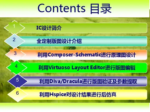
本文将简单的介绍基于ORCAD和L-EDIT的CMOS反相器的电路仿真和版图设计,通过CMOS反相器的电路设计及版图设计过程,我们将了解并熟悉集成电路CAD的一种基本方法和操作过程。
关键词:CMOS反相器ORCAD L-EDIT版图设计AbstractThe huge development potential of CMOS technology itself is the foundation of sustainable development of IC high speed. The manufacturing level of development of the integrated circuit to the deep sub micron technology, CMOS low power consumption, high speed and high integration have been fully reflected. In this paper, the circuit simulation and layout design of ORCAD and L-EDIT CMOS inverter based on simple introduction, through the circuit design and layout design process of CMOS inverter, we will understand and a basic method and operation process, familiar with IC CAD.Keywords: CMOS inverter layout ORCAD L-EDIT绪论20世纪是IC迅速发展的时代。
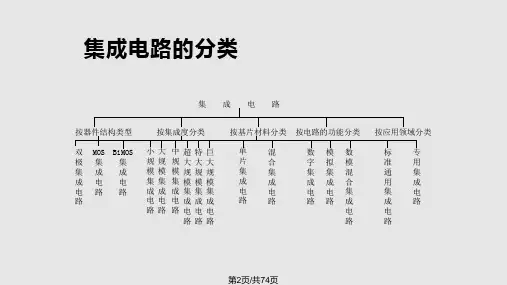
集成电路版图设计什么是集成电路版图设计?所谓的集成电路版图设计是根据逻辑与电路功能和性能要求以及工业水平要求来设计芯片制造时光刻用的掩模版图,实现IC设计的最终输出其中版图是一组相互套合的图形,各层版图表示不同的工艺步骤,每层版图用不同的图案表示。
DRS和LVS开始前需要做哪些准备?DRC开始前需要准备好版图文件和DRC规则文件,LVS开始前需要准备好版图文件、电路图文件和runset文件为什么需要进行版图数据处理?在形成整体的版图并通过DRC、LVS的验证后,版图设计过程就完成了,但这个时候的版图GDS数据还不能拿去制作掩模版,还需要对GDS数据进行处理。
该版图GDS数据中的层次跟最终模板的层次并不是完全一致的,该版图GDS 数据还需要进行工艺涨缩处理,以满足掩模版制作需求。
集成电路设计流程:功能要求、电路设计、电路仿真、版图设计、版图验证、后仿及优化。
光刻工艺流程:底膜处理、涂胶、前烘、曝光、显影、坚膜、显影检测、刻蚀、去胶、最终检验。
工艺要求:特征尺寸、集成度、晶圆尺寸工艺文件夹包含:技术文件、显示文件DRC步骤:建立DRC运行目录、修改规则文件、导出gds2文件、编译规则文件、执行DRC检查、DRC结构分析狗骨电阻的优点:能够控制电流走向,使电阻误差减小。
集成电路发展的趋势是什么?制程工艺越来越精细、集成度越来越高、电路功能越来越强大、越来越趋向于智能化集成电路中的电阻分为哪几种?有扩散电阻、多晶硅电阻、阱电阻简述为什么尽可能多地设计阱接触?能大大减小寄生电阻的阻值,有效抑制闩锁。
在绘制PMOS版图时,为什么在接触区域进行SN注入?SN注入降低了接触电阻,接触孔容易刻蚀,形成欧姆接触。
简述什么是闩锁效应?闩锁效应是CMOS工艺所特有的寄生效应,严重会导致电路的失效,甚至烧毁芯片。
什么是保护环,保护环的主要作用?能抑制闩锁效应的设计方式就是保护环作用: 1.阻碍少子保护环 2.载流子注入类型为少子 3.保护类型为少子 4.电位保持PN结反偏 5.起分流作用。
集成电路设计基础论文题目:CMOS全加器设计学院:信息科学与工程学院专业:集成电路工程姓名:耿烨亮学号:1311082135CMOS全加器设计摘要:现代社会随着电路的集成度越来越高,功耗和信号延迟成为超大规模集成电路的关键。
加法运算是数字系统中最基本的运算,为了更好地利用加法器实现减法、乘法、除法等运算,需要对全加器进行功能仿真设计和分析。
另外通过全加器可以对其它相关电路有所了解。
因此只有深刻理解了全加器的性能才能进一步减小功耗和信号延迟[1]。
本文用对一位全加器进行了全面的分析。
并且通过使用Cadence公司的工具IC 5141与Hspice来实现全定制的整个设计流程。
关键词:全加器;全定制;CadenceAs the circuit’s integration is increasing in the modern society,Power consumption and signal delay is crucial to the design of high-performance very large scale integration circuits. Addition operation is the basic operation of the digital system, In order to achieve much better use of the adder subtraction, multiplication, division and other operations, The need for full adder functional simulation design and analysis is necessary .what’s more, we can understand the other related circuitry through the full adder , Therefore, only a deep understanding of the performance of the full adder can we reduce the power consumption and signal delay.The paper has a comprehensive analysis to the full adder. And through the use of Cadence tool IC 5141 and Hspice to achieve full custom throughout the design process.Key words: the full adder ; Full – Custom; Cadence集成电路设计方法大致可分为定制(Custom)、半定制(Semi-custom)、可编程逻辑器件(PLD)等设计方法,如图1.1所示。