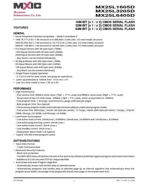
16M-BIT [x 1 / x 2] CMOS SERIAL FLASH 32M-BIT [x 1 / x 2] CMOS SERIAL FLASH 64M-BIT [x 1 / x 2] CMOS SERIAL FLASHFEATURESGENERAL• Serial Peripheral Interface compatible -- Mode 0 and Mode 3• 16M:16,777,216 x 1 bit structure or 8,388,608 x 2 bits (two I/O read mode) structure 32M:33,554,432 x 1 bit structure or 16,772,216 x 2 bits (two I/O read mode) structure 64M:67,108,864 x 1 bit structure or 33,554,432 x 2 bits (two I/O read mode) structure • 512 Equal Sectors with 4K byte each (16Mb)1024 Equal Sectors with 4K byte each (32Mb)2048 Equal Sectors with 4K byte each (64Mb)- Any Sector can be erased individually•32 Equal Blocks with 64K byte each (16Mb)64 Equal Blocks with 64K byte each (32Mb)128 Equal Blocks with 64K byte each (64Mb)- Any Block can be erased individually • Single Power Supply Operation- 2.7 to 3.6 volt for read, erase, and program operations • Latch-up protected to 100mA from -1V to Vcc +1V • Low Vcc write inhibit is from 1.5V to 2.5VPERFORMANCE • High Performance- Fast access time: 86MHz serial clock (15pF + 1TTL Load) and 66MHz serial clock (30pF + 1TTL Load)- Serial clock of two I/O read mode : 50MHz (15pF + TTL Load), which is equivalent to 100MHz - Fast program time: 1.4ms(typ.) and 5ms(max.)/page (256-byte per page)- Byte program time: 9us (typical)- Continuously program mode (automatically increase address under word program mode)- Fast erase time: 60ms(typ.) /sector (4K-byte per sector) ; 0.7s(typ.) /block (64K-byte per block); 14s(typ.) /chip for 16Mb, 25s(typ.) for 32Mb, and 50s(typ.) for 64Mb • Low Power Consumption- Low active read current: 25mA(max.) at 86MHz, 20mA(max.) at 66MHz and 10mA(max.) at 33MHz - Low active programming current: 20mA (max.)- Low active erase current: 20mA (max.)- Low standby current: 20uA (max.)- Deep power-down mode 1uA (typical)• Typical 100,000 erase/program cyclesSOFTWARE FEATURES • Input Data Format- 1-byte Command code •Advanced Security Features - Block lock protectionThe BP0-BP3 status bit defines the size of the area to be software protection against program and erase instructions - Additional 512-bit secured OTP for unique identifier • Auto Erase and Auto Program Algorithm- Automatically erases and verifies data at selected sector- Automatically programs and verifies data at selected page by an internal algorithm that automatically times the program pulse widths (Any page to be programed should have page in the erased state first)MX25L1605D MX25L3205D MX25L6405D元器件交易网•Status Register Feature•Electronic Identification- JEDEC 1-byte manufacturer ID and 2-byte device ID- RES command for 1-byte Device ID- Both REMS and REMS2 commands for 1-byte manufacturer ID and 1-byte device IDHARDWARE FEATURES• SCLK Input- Serial clock input• SI Input- Serial Data Input• SO Output- Serial Data Output• WP#/ACC pin- Hardware write protection and program/erase acceleration• HOLD# pin- pause the chip without diselecting the chip• PACKAGE- 16-pin SOP (300mil)- 8-land WSON (8x6mm or 6x5mm)- 8-pin SOP (200mil, 150mil)- 8-pin PDIP (300mil)- 8-land USON (4x4mm)- All Pb-free devices are RoHS CompliantALTERNATIVE• Security Serial Flash (MX25L1615D/MX25L3215D/MX25L6415D) may provides additional protection features for op-tion. The datasheet is provided under NDA.GENERAL DESCRIPTIONThe MX25L1605D are 16,777,216 bit serial Flash memory, which is configured as 2,097,152 x 8 internally. When it is in two I/O read mode, the structure becomes 8,388,608 bits x 2. The MX25L3205D are 33,554,432 bit serial Flash memory, which is configured as 4,194,304 x 8 internally. When it is in two I/O read mode, the structure becomes 16,772,216 bits x 2. The MX25L6405D are 67,108,864 bit serial Flash memory, which is configured as 8,388,608 x 8 internally. When it is in two I/O read mode, the structure becomes 33,554,432 bits x 2. (please refer to the "Two I/O Read mode" section). The MX25L1605D/3205D/6405D feature a serial peripheral interface and software protocol allowing operation on a simple 3-wire bus. The three bus signals are a clock input (SCLK), a serial data input (SI), and a serial data output (SO). Serial access to the device is enabled by CS# input.When it is in two I/O read mode, the SI pin and SO pin become SIO0 pin and SIO1 pin for address/dummy bits input and data output.The MX25L1605D/3205D/6405D provides sequential read operation on whole chip.After program/erase command is issued, auto program/ erase algorithms which program/ erase and verify the specified page or sector/block locations will be executed. Program command is executed on byte basis, or page (256 bytes) basis, or word basis for Continuously program mode, and erase command is executes on sector (4K-byte), or block (64K-byte), or whole chip basis.To provide user with ease of interface, a status register is included to indicate the status of the chip. The status read command can be issued to detect completion status of a program or erase operation via WIP bit.Advanced security features enhance the protection and security functions, please see security features section for more details.When the device is not in operation and CS# is high, it is put in standby mode and draws less than 20uA DC current. The MX25L1605D/3205D/6405D utilizes MXIC's proprietary memory cell, which reliably stores memory contents even after typical 100,000 program and erase cycles.Table 1. Additional Feature ComparisonPIN CONFIGURATIONSSYMBOL DESCRIPTION CS#Chip SelectSI/SIO0Serial Data Input (for 1 x I/O)/ Serial Data Input & Output (for 2xI/O read mode)SO/SIO1Serial Data Output (for 1 x I/O)/ Serial Data Input & Output (for 2xI/O read mode)SCLK Clock InputWP#/ACCWrite protection: connect to GND ;9.5~10.5V for program/eraseacceleration: connect to 9.5~10.5V HOLD#Hold, to pause the device without deselecting the device VCC + 3.3V Power Supply GNDGroundPIN DESCRIPTION16-PIN SOP (300mil)8-LAND WSON (8x6mm, 6x5mm), USON (4x4mm)8-PIN SOP (200mil, 150mil)PACKAGE OPTIONS16M 32M 64M150mil 8-SOP V 200mil 8-SOP V V 300mil 16-SOP V V V300mil 8-PDIP V V 6x5mm WSON V V 8x6mm WSON V4x4mm USONVV12345678HOLD#VCC NC NC NC NC CS#SO/SIO1161514131211109SCLK SI/SIO0NC NC NC NC GND WP#/ACCCS#SO/SIO1WP#/ACCGND VCC HOLD#SCLK SI/SIO0CS#SO/SIO1WP#/ACC GND VCC HOLD#SCLK SI/SIO01234CS#SO/SIO1WP#/ACC GND 8765VCC HOLD#SCLK SI/SIO08-PIN PDIP (300mil)BLOCK DIAGRAMDATA PROTECTIONThe MX25L1605D/3205D/6405D is designed to offer protection against accidental erasure or programming caused by spurious system level signals that may exist during power transition. During power up the device automatically resets the state machine in the Read mode. In addition, with its control register architecture, alteration of the memory contents only occurs after successful completion of specific command sequences. The device also incorporates several features to prevent inadvertent write cycles resulting from VCC power-up and power-down transition or system noise.•Power-on reset and tPUW: to avoid sudden power switch by system power supply transition, the power-on reset and tPUW (internal timer) may protect the Flash.• Valid command length checking: The command length will be checked whether it is at byte base and completed on byte boundary.• Write Enable (WREN) command: WREN command is required to set the Write Enable Latch bit (WEL) before other command to change data. The WEL bit will return to reset stage under following situation:- Power-up- Write Disable (WRDI) command completion- Write Status Register (WRSR) command completion- Page Program (PP) command completion- Continuously Program mode (CP) instruction completion- Sector Erase (SE) command completion- Block Erase (BE) command completion- Chip Erase (CE) command completion- Write Read-lock Bit (WRLB) instruction completion•Deep Power Down Mode: By entering deep power down mode, the flash device also is under protected from writing all commands except Release from deep power down mode command (RDP) and Read Electronic Signature command (RES).•Advanced Security Features: there are some protection and securuity features which protect content from inadvertent write and hostile access.I. Block lock protection- The Software Protected Mode (SPM) use (BP3, BP2, BP1, BP0) bits to allow part of memory to be protected as read only. The proected area definition is shown as table of "Protected Area Sizes", the protected areas are more flexible which may protect various area by setting value of BP0-BP3 bits.Please refer to table of "protected area sizes".- The Hardware Proteced Mode (HPM) use WP#/ACC to protect the (BP3, BP2, BP1, BP0) bits and SRWD bit.Table 2. Protected Area SizesII. Additional 512-bit secured OTP for unique identifier: to provide 512-bit one-time program area for setting device unique serial number - Which may be set by factory or system customer. Please refer to table 3. 512-bit secured OTP definition.- Security register bit 0 indicates whether the chip is locked by factory or not.- To program the 512-bit secured OTP by entering 512-bit secured OTP mode (with ENSO command), and going through normal program procedure, and then exiting 512-bit secured OTP mode by writing EXSO command.- Customer may lock-down the customer lockable secured OTP by writing WRSCUR(write security register) command to set customer lock-down bit1 as "1". Please refer to table of "security register definition" for security register bit definition and table of "512-bit secured OTP definition" for address range definition.- Note: Once lock-down whatever by factory or customer, it cannot be changed any more. While in 512-bit secured OTP mode, array access is not allowed.Table 3. 512-bit Secured OTP DefinitionAddress range Size Standard Customer LockFactory Lockxxxx00~xxxx0F128-bit ESN (electrical serial number)Determined by customer xxxx10~xxxx3F384-bit N/AHOLD FEATURESHOLD# pin signal goes low to hold any serial communications with the device. The HOLD feature will not stop the operation of write status register, programming, or erasing in progress.The operation of HOLD requires Chip Select(CS#) keeping low and starts on falling edge of HOLD# pin signal while Serial Clock (SCLK) signal is being low (if Serial Clock signal is not being low, HOLD operation will not start until Serial Clock signal being low). The HOLD condition ends on the rising edge of HOLD# pin signal while Serial Clock(SCLK) signal is being low( if Serial Clock signal is not being low, HOLD operation will not end until Serial Clock being low), see Figure 1. Figure 1. Hold Condition OperationThe Serial Data Output (SO) is high impedance, both Serial Data Input (SI) and Serial Clock (SCLK) are don't care during the HOLD operation. If Chip Select (CS#) drives high during HOLD operation, it will reset the internal logic of the device. To re-start communication with chip, the HOLD# must be at high and CS# must be at low.PROGRAM/ERASE ACCELERATIONTo activate the program/erase acceleration function requires ACC pin connecting to 9.5~10.5V voltage (see Figure 2), and then to be followed by the normal program/erase process. By utilizing the program/erase acceleration operation, the performances are improved as shown on table of "ERASE AND PROGRAM PERFORMACE".After power-up ready, it should wait 10ms at least to apply VHH(9.5~10.5V) on the WP#/ACC pin.Figure 2. ACCELERATED PROGRAM TIMING DIAGRAMNote: tVHH (VHH Rise and Fall Time) min. 250nsTable 4. COMMAND DEFINITIONCOMMAND (byte)WREN (writeenable)WRDI (write disable)RDID (read identification )RDSR (read statusregister)WRSR(write status register)READ (read data)FAST READ(fast read data)2READ (2x I/O read command)note1SE (sector erase)1st byte 06 (hex)04 (hex)9F (hex)05 (hex)01 (hex)03 (hex)0B (hex)BB (hex)20 (hex)2nd byte AD1AD1ADD(2)AD13rd byte AD2AD2ADD(2) &Dummy(2)AD24th byte AD3AD3AD35th byte Actionsets the (WEL)write enable latch bit resets the (WEL)write enable latch bitoutputs JEDEC ID:1-byte manufactur er ID & 2-byte device IDto read out the values of the status register to writenew values to the statusregister n bytes read out until CS#goes high n bytes read out until CS#goes high n bytes read out by 2 x I/O until CS#goes high to erase the selectedsector Note 1: The count base is 4-bit for ADD(2) and Dummy(2) because of 2 x I/O. And the MSB is on SI/SIO0 which is different from 1 x I/O conditionCOMMAND (byte)BE (block erase)CE (chip erase)PP (Page program)CP (Continuo-usly program mode)DP (Deep powerdown)RDP (Release from deep power down)RES (read electronic ID)REMS(read electronic manufactu-rer &device ID)REMS2(read ID for 2x I/O mode)1st byte D8 (hex)60 or C7(hex)02 (hex)AD (hex)B9 (hex)AB (hex)AB (hex)90 (hex)EF (hex)2nd byte AD1AD1AD1x x x 3rd byte AD2AD2AD2x x x 4th byte AD3AD3AD3x ADD(note 2)ADD(note2)5th byteAction to erase theselected block to erase whole chip to program the selected page continously program wholechip, theaddress is automatica lly increaseentersdeep power down moderelease from deep power down mode to read out 1-byte device ID outout the manufactu-rer ID &device ID output the manufactu-rer ID &device ID Note 2: ADD=00H will output the manufacturer ID first and ADD=01H will output device ID first Note 3: It is not recommoded to adopt any other code not in the command definition table, which will potentially enter the hidden mode.COMMAND (byte)ENSO (enter secured OTP)EXSO (exit secured OTP)RDSCUR (read security register)WRSCUR (write security register)ESRY (enable SO to output RY/BY#)DSRY (disable SO to output RY/BY#)1st byte B1 (hex)C1 (hex)2B (hex)2F (hex)70 (hex)80 (hex)2nd byte 3rd byte 4th byte 5th byte Actionto enter the 512-bit secured OTP mode to exit the 512-bit secured OTP mode to read value of security registerto set the lock-down bit as "1"(once lock-down,cannot be updated)to enable SO to output RY/BY#during CP mode to disable SO to output RY/BY#during CP modeDummyTable 5-1. Memory Organization (16Mb)Table 5-2. Memory Organization (32Mb)Table 5-3. Memory Organization (64Mb)DEVICE OPERATION1.Before a command is issued, status register should be checked to ensure device is ready for the intended operation.2.When incorrect command is inputted to this LSI, this LSI becomes standby mode and keeps the standby mode until next CS# falling edge. In standby mode, SO pin of this LSI should be High-Z.3.When correct command is inputted to this LSI, this LSI becomes active mode and keeps the active mode until next CS# rising edge.4.Input data is latched on the rising edge of Serial Clock(SCLK) and data shifts out on the falling edge of SCLK. The difference of Serial mode 0 and mode 3 is shown as Figure 3.Figure 3. Serial Modes Supported5.For the following instructions: RDID, RDSR, RDSCUR, READ, FAST_READ, 2READ, RES, REMS and REMS2 the shifted-in instruction sequence is followed by a data-out sequence. After any bit of data being shifted out, the CS# can be high. For the following instructions: WREN, WRDI, WRSR, SE, BE, CE, PP, CP, RDP, DP, ENSO, EXSO,and WRSCUR, the CS# must go high exactly at the byte boundary; otherwise, the instruction will be rejected and not executed.6.During the progress of Write Status Register, Program, Erase operation, to access the memory array is neglected and not affect the current operation of Write Status Register, Program, Erase.Note:CPOL indicates clock polarity of Serial master, CPOL=1 for SCLK high while idle, CPOL=0 for SCLK low while not transmitting. CPHA indicates clock phase. The combination of CPOL bit and CPHA bit decides which Serial mode is supported.SCLKMSBCPHASI 01CPOL 0(Serial mode 0)(Serial mode 3)1SO SCLKMSBCOMMAND DESCRIPTION(1) Write Enable (WREN)The Write Enable (WREN) instruction is for setting Write Enable Latch (WEL) bit. For those instructions like PP, CP, SE, BE, CE, and WRSR, which are intended to change the device content, should be set every time after the WREN instruction setting the WEL bit.The sequence of issuing WREN instruction is: CS# goes low-> sending WREN instruction code-> CS# goes high. (see Figure 12)(2) Write Disable (WRDI)The Write Disable (WRDI) instruction is for resetting Write Enable Latch (WEL) bit.The sequence of issuing WRDI instruction is: CS# goes low-> sending WRDI instruction code-> CS# goes high. (see Figure 13)The WEL bit is reset by following situations:- Power-up- Write Disable (WRDI) instruction completion- Write Status Register (WRSR) instruction completion- Page Program (PP) instruction completion- Sector Erase (SE) instruction completion- Block Erase (BE) instruction completion- Chip Erase (CE) instruction completion- Continuously program mode (CP) instruction completion(3) Read Identification (RDID)The RDID instruction is for reading the manufacturer ID of 1-byte and followed by Device ID of 2-byte. The MXIC Manufacturer ID is C2(hex), the memory type ID is 20(hex) as the first-byte device ID, and the individual device ID of second-byte ID are listed as table of "ID Definitions".The sequence of issuing RDID instruction is: CS# goes low-> sending RDID instruction code -> 24-bits ID data out on SO -> to end RDID operation can use CS# to high at any time during data out. (see Figure. 14)While Program/Erase operation is in progress, it will not decode the RDID instruction, so there's no effect on the cycle of program/erase operation which is currently in progress. When CS# goes high, the device is at standby stage.(4) Read Status Register (RDSR)The RDSR instruction is for reading Status Register Bits. The Read Status Register can be read at any time (even in program/erase/write status register condition) and continuously. It is recommended to check the Write in Progress (WIP) bit before sending a new instruction when a program, erase, or write status register operation is in progress.The sequence of issuing RDSR instruction is: CS# goes low-> sending RDSR instruction code-> Status Register data out on SO (see Figure. 15)The definition of the status register bits is as below:WIP bit. The Write in Progress (WIP) bit, a volatile bit, indicates whether the device is busy in program/erase/write status register progress. When WIP bit sets to 1, which means the device is busy in program/erase/write status register progress. When WIP bit sets to 0, which means the device is not in progress of program/erase/write status register cycle.WEL bit. The Write Enable Latch (WEL) bit, a volatile bit, indicates whether the device is set to internal write enable latch. When WEL bit sets to 1, which means the internal write enable latch is set, the device can accept program/erase/write status register instruction. When WEL bit sets to 0, which means no internal write enable latch; the device will not accept program/erase/write status register instruction. The program/erase command will be ignored and not affect value of WEL bit if it is applied to a protected memory area.BP3, BP2, BP1, BP0 bits. The Block Protect (BP3, BP2, BP1, BP0) bits, non-volatile bits, indicate the protected area(as defined in table 1) of the device to against the program/erase instruction without hardware protection mode being set. To write the Block Protect (BP3, BP2, BP1, BP0) bits requires the Write Status Register (WRSR) instruction to be executed. Those bits define the protected area of the memory to against Page Program (PP), Sector Erase (SE), Block Erase (BE) and Chip Erase(CE) instructions (only if all Block Protect bits set to 0, the CE instruction can be executed).Continuously Program Mode( CP mode) bit. The Continuously Program Mode bit indicates the status of CP mode, "0" indicates not in CP mode; "1" indicates in CP mode.SRWD bit. The Status Register Write Disable (SRWD) bit, non-volatile bit, is operated together with Write Protection (WP#/ ACC) pin for providing hardware protection mode. The hardware protection mode requires SRWD sets to 1 and WP#/ACC pin signal is low stage. In the hardware protection mode, the Write Status Register (WRSR) instruction is no longer accepted for execution and the SRWD bit and Block Protect bits (BP3, BP2, BP1, BP0) are read only.Status Registernote1: see the table "Protected Area Sizes"(5) Write Status Register (WRSR)The WRSR instruction is for changing the values of Status Register Bits. Before sending WRSR instruction, the Write Enable (WREN) instruction must be decoded and executed to set the Write Enable Latch (WEL) bit in advance. The WRSR instruction can change the value of Block Protect (BP3, BP2, BP1, BP0) bits to define the protected area of memory (as shown in table 1). The WRSR also can set or reset the Status Register Write Disable (SRWD) bit in accordance with Write Protection (WP#/ACC) pin signal. The WRSR instruction cannot be executed once the Hardware Protected Mode (HPM)is entered.The sequence of issuing WRSR instruction is: CS# goes low-> sending WRSR instruction code-> Status Register data on SI-> CS# goes high. (see Figure 16)The WRSR instruction has no effect on b6, b1, b0 of the status register.The CS# must go high exactly at the byte boundary; otherwise, the instruction will be rejected and not executed. The self-timed Write Status Register cycle time (tW) is initiated as soon as Chip Select (CS#) goes high. The Write in Progress (WIP) bit still can be check out during the Write Status Register cycle is in progress. The WIP sets 1 during the tW timing,and sets 0 when Write Status Register Cycle is completed, and the Write Enable Latch (WEL) bit is reset.Table 6. Protection ModesNote:1. As defined by the values in the Block Protect (BP3, BP2, BP1, BP0) bits of the Status Register, as shown in Table 1.As the above table showing, the summary of the Software Protected Mode (SPM) and Hardware Protected Mode (HPM).Software Protected Mode (SPM):-When SRWD bit=0, no matter WP#/ACC is low or high, the WREN instruction may set the WEL bit and can changethe values of SRWD, BP3, BP2, BP1, BP0. The protected area, which is defined by BP3, BP2, BP1, BP0, is at software protected mode (SPM).-When SRWD bit=1 and WP#/ACC is high, the WREN instruction may set the WEL bit can change the values of SRWD,BP3, BP2, BP1, BP0. The protected area, which is defined by BP3, BP2, BP1, BP0, is at software protected mode (SPM)ModeStatus register condition Software protection mode(SPM)Status register can be written in (WEL bit is set to "1") and the SRWD, BP0-BP3bits can be changedWP# and SRWD bit status MemoryWP#=1 and SRWD bit=0, or WP#=0 and SRWD bit=0, or WP#=1 and SRWD=1The protected area cannot be program or erase.The protected area cannot be program or erase.WP#=0, SRWD bit=1The SRWD, BP0-BP3 ofstatus register bits cannot be changedHardware protection mode (HPM)Note: If SRWD bit=1 but WP#/ACC is low, it is impossible to write the Status Register even if the WEL bit has previously been set. It is rejected to write the Status Register and not be executed.Hardware Protected Mode (HPM):-When SRWD bit=1, and then WP#/ACC is low (or WP#/ACC is low before SRWD bit=1), it enters the hardware protected mode (HPM). The data of the protected area is protected by software protected mode by BP3, BP2, BP1, BP0 and hardware protected mode by the WP#/ACC to against data modification.Note: to exit the hardware protected mode requires WP#/ACC driving high once the hardware protected mode is entered. If the WP#/ACC pin is permanently connected to high, the hardware protected mode can never be entered; only can use software protected mode via BP3, BP2, BP1, BP0.(6) Read Data Bytes (READ)The read instruction is for reading data out. The address is latched on rising edge of SCLK, and data shifts out on the falling edge of SCLK at a maximum frequency fR. The first address byte can be at any location. The address is automatically increased to the next higher address after each byte data is shifted out, so the whole memory can be read out at a single READ instruction. The address counter rolls over to 0 when the highest address has been reached.The sequence of issuing READ instruction is: CS# goes low-> sending READ instruction code-> 3-byte address on SI -> data out on SO-> to end READ operation can use CS# to high at any time during data out. (see Figure. 17)(7) Read Data Bytes at Higher Speed (FAST_READ)The FAST_READ instruction is for quickly reading data out. The address is latched on rising edge of SCLK, and data of each bit shifts out on the falling edge of SCLK at a maximum frequency fC. The first address byte can be at any location. The address is automatically increased to the next higher address after each byte data is shifted out, so the whole memory can be read out at a single FAST_READ instruction. The address counter rolls over to 0 when the highest address has been reached.The sequence of issuing FAST_READ instruction is: CS# goes low-> sending FAST_READ instruction code-> 3-byte address on SI-> 1-dummy byte address on SI->data out on SO-> to end FAST_READ operation can use CS# to high at any time during data out. (see Figure. 18)While Program/Erase/Write Status Register cycle is in progress, FAST_READ instruction is rejected without any impact on the Program/Erase/Write Status Register current cycle.(8) 2 x I/O Read Mode (2READ)The 2READ instruction enable double throughput of Serial Flash in read mode. The address is latched on rising edge of SCLK, and data of every two bits(interleave on 2 I/O pins) shift out on the falling edge of SCLK at a maximum frequency fT. The first address byte can be at any location. The address is automatically increased to the next higher address after each byte data is shifted out, so the whole memory can be read out at a single 2READ instruction. The address counter rolls over to 0 when the highest address has been reached. Once writing 2READ instruction, the following address/dummy/ data out will perform as 2-bit instead of previous 1-bit.The sequence of issuing 2READ instruction is: CS# goes low→ sending 2READ instruction→ 24-bit address interleave on SIO1 & SIO0→ 8-bit dummy interleave on SIO1 & SIO0→ data out interleave on SIO1 & SIO0→ to end 2READ operation can use CS# to high at any time during data out (see Figure of 2 x I/O Read Mode Timing Waveform)While Program/Erase/Write Status Register cycle is in progress, 2READ instruction is rejected without any impact on the Program/Erase/Write Status Register current cycle.The 2 I/O only perform read operation. Program/Erase /Read ID/Read status/Read ID....operation do not support 2 I/O throughputs.(9) Sector Erase (SE)The Sector Erase (SE) instruction is for erasing the data of the chosen sector to be "1". The instruction is used for any 4K-byte sector. A Write Enable (WREN) instruction must execute to set the Write Enable Latch (WEL) bit before sending the Sector Erase (SE). Any address of the sector (see table 3) is a valid address for Sector Erase (SE) instruction. The CS# must go high exactly at the byte boundary (the latest eighth of address byte been latched-in); otherwise, the instruction will be rejected and not executed.Address bits [Am-A12] (Am is the most significant address) select the sector address.The sequence of issuing SE instruction is: CS# goes low -> sending SE instruction code-> 3-byte address on SI -> CS# goes high. (see Figure 22)The self-timed Sector Erase Cycle time (tSE) is initiated as soon as Chip Select (CS#) goes high. The Write in Progress (WIP) bit still can be check out during the Sector Erase cycle is in progress. The WIP sets 1 during the tSE timing, and sets 0 when Sector Erase Cycle is completed, and the Write Enable Latch (WEL) bit is reset. If the page is protected by BP3, BP2, BP1, BP0 bits, the Sector Erase (SE) instruction will not be executed on the page.(10) Block Erase (BE)The Block Erase (BE) instruction is for erasing the data of the chosen block to be "1". The instruction is used for 64K-byte sector erase operation. A Write Enable (WREN) instruction must execute to set the Write Enable Latch (WEL) bit before sending the Block Erase (BE). Any address of the block (see table 3) is a valid address for Block Erase (BE) instruction. The CS# must go high exactly at the byte boundary (the latest eighth of address byte been latched-in); otherwise, the instruction will be rejected and not executed.The sequence of issuing BE instruction is: CS# goes low -> sending BE instruction code-> 3-byte address on SI -> CS# goes high. (see Figure 23)The self-timed Block Erase Cycle time (tBE) is initiated as soon as Chip Select (CS#) goes high. The Write in Progress (WIP) bit still can be check out during the Sector Erase cycle is in progress. The WIP sets 1 during the tBE timing, and sets 0 when Sector Erase Cycle is completed, and the Write Enable Latch (WEL) bit is reset. If the page is protected by BP3, BP2, BP1, BP0 bits, the Block Erase (BE) instruction will not be executed on the page.(11) Chip Erase (CE)The Chip Erase (CE) instruction is for erasing the data of the whole chip to be "1". A Write Enable (WREN) instruction must execute to set the Write Enable Latch (WEL) bit before sending the Chip Erase (CE). Any address of the sector (see table 3) is a valid address for Chip Erase (CE) instruction. The CS# must go high exactly at the byte boundary( the latest eighth of address byte been latched-in); otherwise, the instruction will be rejected and not executed.The sequence of issuing CE instruction is: CS# goes low-> sending CE instruction code-> CS# goes high. (see Figure 24)。