PS1
- 格式:rtf
- 大小:33.00 KB
- 文档页数:2
PS1中文游戏全集本合集特征:◆单个压缩,减小体积,方便下载◆标注简繁体、汉化版本等信息◆多CD游戏按每CD一个文件压缩,只需下载CD1即可开始游戏◆版本收录考究◆无毒、无插件、无捆绑◆为防止网络一键转卖,添加解压密码oldmanemu. n et(去掉空格)完整清单:PS1CH001 –最终幻想战略版[简][070806]PS1CH002 – Forget me not 勿忘我-调色板-[简][V1.0]PS1CH003 – RPG工具4[简][V1.0]PS1CH004 – SD高达G世纪[简][091016]PS1CH005 – SRPG制作工具[简][V1.0]PS1CH006 –阿兰多拉[简][V1.1]PS1CH007 –霸王的大陆[简][V1.4]PS1CH008 –北欧女神[简][V1.04]Disc APS1CH009 –北欧女神[简][V1.04]Disc BPS1CH010 –超级机器人大战F[简][v1.0Fix][WGF]PS1CH011 –超级机器人大战F完结篇[简][汉化测试版](汉化至约60话) PS1CH012 –超级机器人大战α[简][130629]PS1CH013 –超级机器人大战α外传[简][SLPS-03147-V1.1][V1.0][WGF] PS1CH014 –超级机器人大战α外传[简][SLPS-03577-V1.2][V1.0][WGF]PS1CH015 –沉默爆破手[简][V1.0]PS1CH016 –穿越时空2[简][V1.0]Disc APS1CH017 –穿越时空2[简][V1.0]Disc BPS1CH018 –大航海时代外传[简][v190916][ciosddr]PS1CH019 –弟切草苏生篇[简][意志之路+扑家汉化组]PS1CH020 –第2次超级机器人大战[简][BetaV3]PS1CH021 –恶魔城X –月下夜想曲[简][V2.0Fix]PS1CH022 –放浪冒险谭[简][V1.0]PS1CH023 –放浪冒险谭[简][V1.1]PS1CH024 –放浪冒险谭[简][v1.22][小混蛋]PS1CH025 –封神演义爱藏版[简][V1.1]PS1CH026 –格兰蒂亚[简][V1.1]Disc APS1CH027 –格兰蒂亚[简][V1.1]Disc BPS1CH028 –幻想大陆战记[简][V1.0]Disc APS1CH029 –幻想大陆战记[简][V1.0]Disc BPS1CH030 –幻想大陆战记初代[简][V1.0]PS1CH031 –皇牌空战2[简][V1.0]PS1CH032 –寄生前夜[简][汉化修正版]Disc APS1CH033 –寄生前夜[简][汉化修正版]Disc BPS1CH034 –寄生前夜2[简][第三版]Disc APS1CH035 –寄生前夜2[简][第三版]Disc BPS1CH036 –寂静岭[简][V1.0]PS1CH037 –街~命运的交叉点~[简][Day1-Day4汉化测试版20190829][施珂昱]Disc APS1CH038 –街~命运的交叉点~[简][Day1-Day4汉化测试版20190829][施珂昱]Disc BPS1CH039 –卡片召唤师[简][V1.0]PS1CH040 –柯南–三人的名推理[简][V0.99]PS1CH041 –尤特娜英雄战记泪之指环传说[简][v1.0][フェニックス]PS1CH042 –恐怖惊魂夜镰鼬之夜特别篇[简][V1.0][魔幻学院]PS1CH043 –灵魂黑客[简][V1.0]Disc APS1CH044 –灵魂黑客[简][V1.0]Disc BPS1CH045 –龙骑士传说[简][v1.0][龙骑士传说吧+意志之路]Disc APS1CH046 –龙骑士传说[简][v1.0][龙骑士传说吧+意志之路]Disc BPS1CH047 –龙骑士传说[简][v1.0][龙骑士传说吧+意志之路]Disc CPS1CH048 –龙骑士传说[简][v1.0][龙骑士传说吧+意志之路]Disc DPS1CH049 –玛娜传奇[简][V0.8]PS1CH050 –梦幻模拟战1&2 加强版[简][V4.2][痕]PS1CH051 –梦幻模拟战4[简][081023]PS1CH052 –梦幻模拟战5[简][v1.1][WGF]PS1CH053 –梦幻骑士[简][V1.2]Disc APS1CH054 –梦幻骑士[简][V1.2]Disc BPS1CH055 –拳皇京[简][BETA]PS1CH056 –三国志4[繁][官方]PS1CH057 –三国志5[繁][官方]PS1CH058 –三国志5PK[简][未知]PS1CH059 –三国志7[简][V1.0]PS1CH060 –三国志孔明传[简][Final]PS1CH061 –沙加开拓者[简][V1.0]PS1CH063 –少年佣兵团[简][v2.03][WGF]PS1CH064 –射雕英雄传[简][繁][官方]PS1CH065 –生化危机2[简][V3.0]Disc APS1CH066 –生化危机2[简][V3.0]Disc BPS1CH067 –生化危机3[简][20110815]PS1CH068 –胜利十一人2000[繁][V1.0]PS1CH069 –胜利十一人2002[简][V1.0]PS1CH070 –水浒演武[官方]PS1CH071 –太阳的表决[简][V1.0]PS1CH072 –天诛忍凯旋[简][Beta]PS1CH073 –玩具之梦[简][v1.0][劲草]PS1CH074 –我是东巴2[简][v1.1][劲草](仅限模拟器运行) PS1CH075 –午夜列车[简][V1.0]Disc APS1CH076 –午夜列车[简][V1.0]Disc BPS1CH077 –武藏传[简][劲草][v1.1](仅限模拟器运行) PS1CH078 –武士枪手(回升之斩)[繁]PS1CH079 –西游记[简][V1.1]PS1CH080 –笑笑江湖大富翁[繁][官方]PS1CH081 –星之刃[简][V1.0]PS1CH082 –异度装甲[简][v1.22][Agemo]Disc APS1CH083 –异度装甲[简][v1.22][Agemo]Disc BPS1CH084 –永恒传说[简][V0.8]Disc APS1CH085 –永恒传说[简][V0.8]Disc BPS1CH087 –勇者斗恶龙怪兽篇1+2[简][V1.0]PS1CH088 –织田信长传[繁][V1.02]PS1CH089 –钟楼首度恐惧[简][V1.0]PS1CH090 –最终幻想2[简][繁][V1.0]PS1CH091 –最终幻想7[简][V1.0]Disc APS1CH092 –最终幻想7[简][V1.0]Disc BPS1CH093 –最终幻想7[简][V1.0]Disc CPS1CH094 –最终幻想8[简][V1.0]Disc APS1CH095 –最终幻想8[简][V1.0]Disc BPS1CH096 –最终幻想8[简][V1.0]Disc CPS1CH097 –最终幻想8[简][V1.0]Disc DPS1CH098 –最终幻想8[简][v1.0修正第三版]Disc A(去除RHP,不死机,不乱码) PS1CH099 –最终幻想8[简][v1.0修正第三版]Disc B(去除RHP,不死机,不乱码) PS1CH100 –最终幻想8[简][v1.0修正第三版]Disc C(去除RHP,不死机,不乱码) PS1CH101 –最终幻想8[简][v1.0修正第三版]Disc D(去除RHP,不死机,不乱码) PS1CH102 –最终幻想9[简][V2.0]Disc APS1CH103 –最终幻想9[简][V2.0]Disc BPS1CH104 –最终幻想9[简][V2.0]Disc CPS1CH105 –最终幻想9[简][V2.0]Disc DPS1CH106 –本格派四人麻将俱乐部[简][V1.0][施珂昱]PS1CH107 –恶魔召唤师灵魂黑客[简][v1.0fix][monkeyking]Disc APS1CH108 –恶魔召唤师灵魂黑客[简][v1.0fix][monkeyking]Disc BPS1CH109 –疯狂大屋2 基顿和他的叔叔[繁][v1.0][官方]PS1CH110 –劲爆热鼠[繁][v1.0][戏谷资讯]PS1CH111 –麻将写真馆[繁][v1.0][官方]PS1CH112 –麻将学园三合一[繁][v1.0][官方]PS1CH113 –秦始皇[繁][v1.0][官方]PS1CH114 –三国无双[简][v1.0][gorosega]PS1CH115 –三国志 5 威力加强版[简][v1.0][寂寞的冬]PS1CH116 –胜利十一人实况足球甲A联赛[简][v1.0]PS1CH117 –台湾麻将风云再起[繁][v1.0][官方]PS1CH118 –台湾麻将首部曲[繁][v1.0][官方]PS1CH119 –钟楼幽灵之首[简][v1.0][扑家汉化组]PS1CH120 –牧场物语中秋满月[简][v1.0][劲草]PS1CH121 –真魔装机神[简][剧情汉化版][WGF]PS1CH122 –北斗神拳世纪末救世主传说[简][爱玩帝]PS1CH123 –猫犬协奏曲[简][神州国光社]PS1CH124 –真说侍魂武士道列传[简][机翻体验版][作者未知]下载地址1(百度云盘) 访问码:byhw下载地址2(城通网盘) 访问码:oldman。
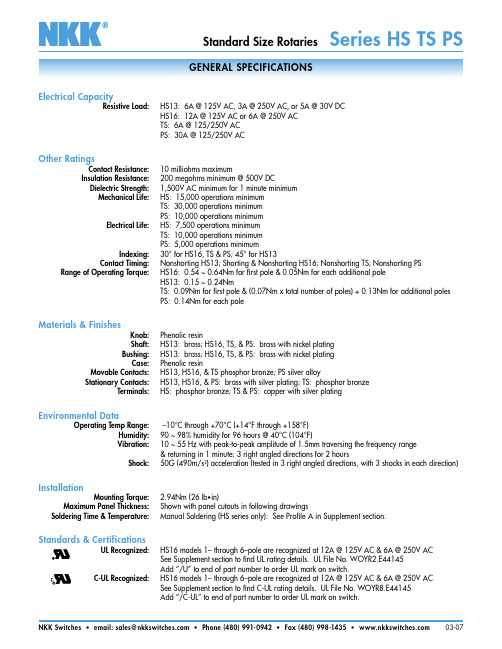
Standard Size Rotaries Series HS TS PSGENERAL SPECIFICATIONSElectrical CapacityResistive Load:HS13: 6A @ 125V AC, 3A @ 250V AC, or 5A @ 30V DCHS16: 12A @ 125V AC or 6A @ 250V ACTS: 6A @ 125/250V ACPS: 30A @ 125/250V ACOther RatingsContact Resistance: 10 milliohms maximumInsulation Resistance: 200 megohms minimum @ 500V DCDielectric Strength:1,500V AC minimum for 1 minute minimumMechanical Life:HS: 15,000 operations minimumTS: 30,000 operations minimumPS: 10,000 operations minimumElectrical Life:HS: 7,500 operations minimumTS: 10,000 operations minimumPS: 5,000 operations minimumIndexing: 30° for HS16, TS & PS; 45° for HS13Contact Timing: Nonshorting HS13; Shorting & Nonshorting HS16; Nonshorting TS; Nonshorting PS Range of Operating Torque:HS16: 0.54 ~ 0.64Nm for first pole & 0.05Nm for each additional poleHS13: 0.15 ~ 0.24NmTS: 0.09Nm for first pole & (0.07Nm x total number of poles) + 0.13Nm for additional polesPS: 0.14Nm for each poleMaterials & FinishesKnob:Phenolic resinShaft:HS13: brass; HS16, TS, & PS: brass with nickel platingBushing:HS13: brass; HS16, TS, & PS: brass with nickel platingCase:Phenolic resinMovable Contacts:HS13, HS16, & TS phosphor bronze; PS silver alloyStationary Contacts:HS13, HS16, & PS: brass with silver plating; TS: phosphor bronzeTerminals:HS: phosphor bronze; TS & PS: copper with silver platingEnvironmental DataOperating Temp Range: –10°C through +70°C (+14°F through +158°F)Humidity:90 ~ 98% humidity for 96 hours @ 40°C (104°F)Vibration:10 ~ 55 Hz with peak-to-peak amplitude of 1.5mm traversing the frequency range& returning in 1 minute; 3 right angled directions for 2 hoursShock:50G (490m/s2) acceleration (tested in 3 right angled directions, with 3 shocks in each direction)InstallationMounting Torque: 2.94Nm (26 lb•in)Maximum Panel Thickness:Shown with panel cutouts in following drawingsSoldering Time & Temperature:Manual Soldering (HS series only): See Profile A in Supplement section.Standards & CertificationsUL Recognized:HS16 models 1– through 6–pole are recognized at 12A @ 125V AC & 6A @ 250V ACSee Supplement section to find UL rating details. UL File No. WOYR2.E44145Add “/U” to end of part number to order UL mark on switch.C-UL Recognized:HS16 models 1– through 6–pole are recognized at 12A @ 125V AC & 6A @ 250V ACSee Supplement section to find C-UL rating details. UL File No. WOYR8.E44145Add “/C-UL” to end of part number to order UL mark on switch.Switch is viewed from shaft end and shown in position 1. Terminal numbers are not on switch. Standard Hardware shown on last page of this section.Maximum Effective Panel ThicknessWith Locking Ring .150” (3.8mm)Without Locking Ring .189” (4.8mm)Maximum Effective Panel ThicknessWith Locking Ring .189” (4.8mm)Without Locking Ring .228” (5.8mm)• On each deck of multipole devices common and load terminals are in the same positions as shown in the schematic above.• Switch is viewed from the shaft end and shown in position 1.• Terminal numbers are on the switch bottom. Stopper positions are molded on the top of the switch.• Standard Hardware shown on last page of this section.HS16-2NHS13X.236.236• Standard Hardware shown on last page of this section.Maximum Effective Panel ThicknessWith Locking Ring.189” (4.8mm)Without Locking Ring.228” (5.8mm)Panel Cutouts BottomTopTS5N.236• Standard Hardware shown on last page of this section.Panel Cutout BottomTopPS4NMaximum Effective Panel ThicknessWithout Locking Ring.189” (4.8mm).236Standard Size RotariesSeries HS TS PSShaftSHAFT TYPESOPTIONAL KNOBS FOR D FLAT SHAFTSSTOPPER SETTINGD Flat Shaft For use withAT431 and AT432Knurled ShaftNot for use with AT431 or AT432Knob Orientation The rotary knobs used on the D-flat shafts can be oriented on the switch to suit the customer’s particular front panel needs simply by sliding the knob over the square adaptor at the preferred orientation.AT432Small Knob Phenolic Resin Black only with whiteindicator lineFor HS16, TS, & PS ModelsThe HS16, TS, and PS switches are supplied with the stopper plate set for the maximum number of positions allowed for that model. Prior to installation, the desired stopper setting should be made:1. Be sure the shaft is turned counterclockwise to the extreme left. If theshaft is not turned counterclockwise to the extreme left, proper setting cannot be achieved.2. Loosen the nut far enough to allow raising the stopper plate for resetting.3. Insert the stopper in the numbered hole for the desired stopper setting.Satisfactory switch functioning cannot be assured if the stopper plate is not properly positioned.4. Tighten the nut firmly against the stopped plate.Standard Hardware Supplied with HS, TS, and PS:AT526 Hex Mounting Nut (quantity 3)AT518 Locking Ring (quantity 1)AT520 Split Lockwasher (quantity 1)Use of mounting supports on PS is optional; screws are not provided.AT431Large Knob Black only with white indicatorline。


ps1游戏列表PS1游戏列表本文档为PS1游戏列表,包含了所有发布的PS1游戏的详细信息。
一、动作游戏1.《合金装备》- 发行日期.1998年9月3日- 游戏类型:动作冒险- 游戏平台:PlayStation- 游戏简介:玩家扮演的角色“蛇”必须完成各种任务来阻止一场核战争的爆发。
2.《生化危机》- 发行日期.1996年3月22日- 游戏类型:生存恐怖- 游戏平台:PlayStation- 游戏简介:玩家在一个被感染的城市中生存,同时需要解开谜题和击败各种变异怪物。
二、角色扮演游戏1.《最终幻想VII》- 发行日期.1997年1月31日- 游戏类型:角色扮演- 游戏平台:PlayStation- 游戏简介:玩家控制一个叫做“云”的男主角,与其他角色一起抵抗一个企图统治世界的邪恶势力。
2.《勇者斗恶龙VII》- 发行日期.2000年8月26日- 游戏类型:角色扮演- 游戏平台:PlayStation- 游戏简介:玩家扮演一个勇者,通过战斗、探索和解谜来解救被邪恶势力侵袭的世界。
三、竞速游戏1.《极品飞车:地下狂飙》- 发行日期.1998年11月17日- 游戏类型:竞速- 游戏平台:PlayStation- 游戏简介:玩家可以在城市中驾驶各种豪华汽车进行街头赛车,同时需要躲避警察追捕。
2.《格兰特里斯谢尔2》- 发行日期.1999年12月23日- 游戏类型:竞速- 游戏平台:PlayStation- 游戏简介:玩家通过驾驶赛车在不同赛道上比赛,获得胜利后可以解锁更多的赛车和道具。
附件:无法律名词及注释:1.发行日期:指游戏正式上市销售的日期。
2.游戏类型:指游戏所属的主要游戏类别,如动作、角色扮演、竞速等。
3.游戏平台:指游戏发布的主要游戏平台,如PlayStation、Xbox等。
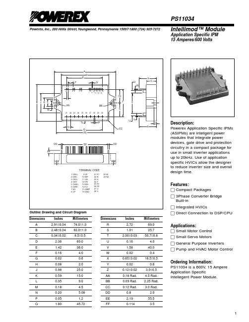
Powerex, Inc., 200 Hillis Street, Youngwood, Pennsylvania 15697-1800 (724) 925-7272Intellimod™ ModuleApplication Specific IPM 15 Amperes/600 VoltsPS11034Description:Powerex Application Specific IPMs (ASIPMs) are inteligent power modules that integrate powerdevices, gate drive and protection circuitry in a compact package for use in small inverter applications up to 20kHz. Use of application specific HVICs allow the designer to reduce inverter size and overall design time.Features:□Compact Packages□3Phase Converter Bridge Built-in□Integrated HVICs□Direct Connection to DSP/CPUApplications:□Small Motor Control □Small Servo Motors□General Purpose Inverters□Pump and HVAC Motor Control Ordering Information:PS11034 is a 600V , 15 Ampere Application SpecificIntellegent Power Module.DimensionsInches Millimeters A 2.91±0.0474.0±1.0B 2.48±0.0463.0±1.0C 0.34±0.028.5±0.5D 2.3660.0E 1.4236.0F 0.16 4.0G 0.020.6H 0.08 2.0J 0.9825.0K 0.5915.0L 0.359.0M 0.18 4.5N 0.20 5.08P 0.05 1.2Q1.8045.72DimensionsInches Millimeters R 2.7269.0S 1.0125.7T 2.00±0.0350.7±0.8U 0.16 4.0V 1.5840.0W 0.020.4X 0.65±0.0216.5±0.5Y 0.020.6Z 0.12±0.02 3.0±0.5AA 0.18 Rad. 4.5 Rad.BB 0.09 Rad. 2.25 0.12 Rad. 3.0 Rad.DD 0.8 2.0EE 2.1955.5FF0.1143.5Outline Drawing and Circuit DiagramPowerex, Inc., 200 Hillis Street, Youngwood, Pennsylvania 15697-1800 (724) 925-7272PS11034Intellimod™ ModuleApplication Specific IPM15 Amperes/600 VoltsAbsolute Maximum Ratings, T j = 25°C unless otherwise specifiedCharacteristics Symbol PS11034Units Power Device Junction T emperature*T j-20 to 125°C Storage Temperature T stg-40 to 125°C Case Operating Temperature (See T C Measure Point Illustration)T C-20 to 100°C Mounting Torque, M4 Mounting Screws—13in-lb Module Weight (Typical)—70Grams Isolation Voltage**V ISO2500Volts *The indicated values are specified considering the safe operation of all the parts within the ASIPM. The maximum rating for the ASIPM power chips (IGBT & FWDi) is T j < 150.**60 Hz sinusoidal AC applied between all terminals and the base plate for 1 minute.IGBT Inverter SectorSupply Voltage (Applied between P2 - N2)V CC450Volts Supply Voltage, Surge (Applied between P2 - N2, Surge-Value)V CC(surge)500Volts Each IGBT Collector-Emitter Static Voltage (Applied between P2-U.V.W, U.V.W-N2)V P or V N600Volts Each IGBT Collector-Emitter Switching Voltage V P(S) or V N(S)600Volts (Applied between P2-U.V.W, U.V.W-N2 (Pulse))Each IGBT Collector Current, T C = 25°C, “( )” means I C Peak Value±I C(±I CP)±15 (±30)AmperesConverter SectorRepetitive Peak Reverse Voltage V RRM800Volts Recommended AC Input Voltage E a220Vrms DC Output Current (3-phase Rectifying Circuit)I DC15 A Surge (Non-repetitive) Forward Current (1 Cycle at 60Hz, Peak Value Non-repetitive)I FSM150AI2t for Fusing (Value for One Cycle of Surge Current)I2t93A2sControl SectorSupply Voltage V D,V DB-0.5 ~ 20Volts Input Signal Voltage V CIN-0.5 ~ 7.5Volts Fault Output Supply Voltage V FO-0.5 ~ 7.5Volts Fault Output Current I FO15mA DC-Link IGBT Current Signal Amp Output Current I AMP1mAPS11034Intellimod ™ ModuleApplication Specific IPM 15 Amperes/600 VoltsPowerex, Inc., 200 Hillis Street, Youngwood, Pennsylvania 15697-1800 (724) 925-7272Electrical and Mechanical Characteristics, T j = 25°C unless otherwise specifiedCharacteristicsSymbolTest ConditionsMin.Typ.Max.UnitsIGBT Inverter SectorCollector-Emitter Saturation Voltage V CE(sat)I C = 15A, T j = 25°C, V D = V DB = 15V ,——2.9VoltsInput = ON (Shunt Voltage Drop Not Included)Diode Forward Voltage V EC T j = 25°C, -I C = 15A —— 2.9Volts Converter Diode VoltageV FR T j = 25°C, I FR = 10A —— 1.5Volts Converter Diode Reverse Current I RRM V R = V RRM , T j = 125°C——8mA Switching Timeson C(on)CC C j off D DB C(off)on off rrShort Circuit Endurance (Output, Arm, and @V CC ≤ 400V , Input = 5V → 0V (One-shot),• No DestructionLoad Short-Circuit Modes)-20°C ≤ T j(start) ≤ 125°C,• F O Output by Protection Operation13.5V ≤ V D = V DB ≤ 16.5V Switching SOA@V CC ≤ 400V , Input = 5V → 0V ,• No DestructionT j ≤ 125°C, I C < OC T rip Level,• No Protecting Operation 13.5V ≤ V D = V DB ≤ 16.5V• No F O Output T C Measure PointCPowerex, Inc., 200 Hillis Street, Youngwood, Pennsylvania 15697-1800 (724) 925-7272PS11034Intellimod™ ModuleApplication Specific IPM15 Amperes/600 VoltsElectrical and Mechanical Characteristics, T j = 25°C unless otherwise specifiedCharacteristics Symbol Test Conditions Min. Typ.Max.UnitsControl SectorCircuit Current (Average)I D T j = 25°C, V D = 15V, V IN = 5V——50mAI DB T j = 25°C, V D = V DB = 15V, V IN = 5V——5mA Input ON Threshold Voltage V th(on)0.8 1.4 2.0Volts Input OFF Threshold Voltage V th(off) 2.5 3.0 4.0Volts Input Pull-up Resistor Ri Applied between—50—kΩInput Terminal-inside Power SupplyPWM Input Frequency f PWM T C≤ 100°C, T j≤ 125°C1—15kHz Arm Shoot-through Blocking Time*t DEAD Relates to Corresponding Inputs 2.2——µST C = -20°C ~ 100°CInput Interlock Sensing t int Relates to Corresponding Input—100—ns Inverter DC-link IGBT Current V amp 100%I C = I OP(100%), V D = 15V, T j = 25°C 1.5 2.0 2.5Volts Sense Voltage Output Signal** V amp 200%I C = I OP(200%), V D = 15V, T j = 25°C 3.0 4.0 5.0Volts Inverter DC-link IGBT Current V amp 250%I C = I OP(250%), V D = 15V 5.0——Volts Sense Voltage Output Limit** V amp 0%I C = I OP(0%), V D = 15V—50100mV Over-Current Trip Level OC14.217.725.0AmperesOC jShort-Circuit Trip Level SC—30—AmperesSCTrip Level UV D11.012.013.0Volts Supply Circuit Reset Level UV Dr11.512.513.5Volts Under-Voltage DB C jProtection Reset Level UV DBr10.611.312.1Volts Delay Time t dV—10—µS Fault Output Pulse Width***t FO T j = 25°C 1.0 1.8—mS Fault Output Current***I Fo(H)Open Collector Output——1µAFo(L)* The dead-time has to be set externally by the CPU; it is not part of the ASIPM internal functions.**Refer ro the graph on next page.***Fault output signalling is given only when the internal OC, SC, and UV protection circuits are activated. The OC, SC and UV protection (and fault output) operate for the lower arms only. The OC and SC protection fault output is given in a pulse format while that of UV protection is maintained thrpughout the duration of the under-voltage condition.PS11034Intellimod ™ ModuleApplication Specific IPM 15 Amperes/600 VoltsPowerex, Inc., 200 Hillis Street, Youngwood, Pennsylvania 15697-1800 (724) 925-7272Thermal CharacteristicsCharacteristic Symbol Condition Min. Typ.Max.Units Junction to CaseR th(j-c)Q Each IGBT —— 2.8°C/Watt R th(j-c)D Each FWDi —— 3.9°C/Watt R th(j-c)DREach Converter —— 4.8°C/Watt Contact Thermal ResistanceR th(c-f)Case to Fin Per Module.——0.074°C/WattThermal Grease AppliedRecommended Conditions for UseCharacteristic Symbol ConditionMin.Typ.Value Units Supply Voltage V CCApplied across P2-N2 Terminals —300400Volts Control Supply VoltageV D Applied between V D -GND 13.515.016.5Volts V DBApplied between CBU+ & CBU-,13.515.016.5VoltsCBV+ & CBV-, CBW+ & CBW-Control Supply dv/dt dV D /dt, dV DB /dt-1—1V/µs Input ON Voltage V CIN(on)Applied between 0—0.8Volts CIN(off)P P P N N N Module Case Operating Temperature T C ——100°C PWM Input Frequencyf PWM T C ≤ 100°C, T j ≤ 125°C ——15kHz Allowable Minimum Input On-pulse Width t XX 1——µS Arm Shoot-through Blocking Timet DEADRelate to Corresponding Inputs2.2——µSC U R R E N T S E N SE V O L T A G EO U T P U T S I G N A L ,V A M P , (V O L T S )INVERTER DC-LINK IGBT CURRENT ANALOG SIGNALING (TYPICAL)510020043210300ACTUAL LOAD PEAK CURRENT, (%), (I C = I O X ͌2 )PS11034Intellimod ™ ModuleApplication Specific IPM 15 Amperes/600 VoltsPowerex, Inc., 200 Hillis Street, Youngwood, Pennsylvania 15697-1800 (724) 925-72722112–+–+–+V DU P V P W U N V N W F V Functional Block Diagram。
Alco ControlsPressure Controls PS1 / PS2 SeriesTechnical BulletinAdjustable Single and Dual Pressure Controls for high and low pressureapplications.Features• Adjustable pressure range• Narrow adjustable differential depending on model• Range and differential pointer in units bar and psig• Range and differential individually lockable by wire seal• High rated SPDT contacts for all versions• Shatter resistant contacts• Heavy duty, finger-proof terminal blocks• Captive terminal and cover screws• Dual pressostats with two independent SPDT switches• Manual toggle for system checkout and override• Standard pressure connection 7/16”-20 UNF for1/4” SAE male flare connection• Low pressure and high pressure versions available withTÜV approval according to EN 12263 to meet requirements ofDIN 8901 and EN 378• Automatic and manual reset versions• Some versions with convertible auto/manual reset• Locking plate and mounting screws includedOptions (minimum lot size 100 pieces)• Alternative pressure connectors including 6 mm ODF solder connection• Factory set to customer specificationSingle Pressostat PS1Dual Pressostat PS2 Selection Table Single Pressure Controls PS1Type PCNAdjustment RangeUpperSetpointbarDifferentialSetpointbarLowestSetpointbarFactorySettingbarLeakage TestPressurebarPressureConnectionLow Pressure ControlsPS1-A3A 4 370 700-0.5 … 7 0.5 … 5 -0.9 3.5 / 4.5 24 7/16”-20 UNFPS1-A3K 4 370 600 capillary/nut PS1-A3L 4 714 945 cap./solder tube ¼“ PS1-A3U 4 712 201 solder 6 mm PS1-A3X 4 713 430 solder tube ¼“PS1-R3A 4 350 100-0.5 … 7 External resetapprox. 1barabove setpoint-0.9 3.5 247/16”-20 UNFPS1-R3K 4 713 431 Capillary/nut High Pressure ControlsPS1-A5A 4 350 5006 … 31 2 … 15 3 16 / 20 35 7/16”-20 UNFPS1-A5K 4 370 400 capillary/nut PS1-A5L 4 715 136 cap./solder tube ¼“ PS1-A5U 4 713 325 solder 6 mm PS1-A5X 4 713 434 solder tube ¼”PS1-R5A 4 350 7006 … 31 External resetapprox. 3barbelow setpoint- 20 357/16”-20 UNFPS1-R5K 4 370 300 capillary/nutSelection Table Single Pressure Controls PS1 TÜV (EN 12263)Type PCNAdjustment RangeUpperSetpointbarDifferentialSetpointbarLowestSetpointbarFactorySettingbarLeakage TestPressurebarPressureConnectionPressure Limiter for low pressure protection EN 12263 PSL (automatic reset)PS1-W3A 4 368 300-0.5 … 7 0.5 … 5 -0.9 3.5 / 4.5 24 7/16”-20 UNFPS1-W3U 4 713 437 solder 6 mm Pressure Cut Out for low pressure protection EN 12263 PZL (external reset)PS1-B3A 4 470 400-0.5 … 7 External resetapprox. 1barabove setpoint-0.9 3.5 247/16”-20 UNFPS1-B3U 4 715 141 solder 6 mm Pressure Limiter for high pressure protection EN 12263 PSH (automatic reset)PS1-W5A 4 353 2006 … 31 2 … 15 3 16 / 20 35 7/16”-20 UNFPS1-W5K 4 359 100 capillary/nut PS1-W5U 4 713 439 solder 6 mm Pressure Cut Out for high pressure protection EN 12263 PZH (external manual reset)PS1-B5A 4 353 3006 … 31 External resetapprox. 3barbelow setpoint- 20 357/16”-20 UNFPS1-B5J 4 715 758 cap./solder 6mm PS1-B5U 4 712 332 solder 6 mm Safety Pressure Cut Out for high pressure protection EN 12263 PZHH (internal manual reset)PS1-S5A 4 368 4006 … 31 Internal resetapprox. 3barbelow setpoint- 21 357/16”-20 UNFPS1-S5U 4 711 591 solder 6 mm Selection Table Dual Pressure Controls PS2Type PCNAdjustment Range Factory Setting Leakage TestUpper Setpoint Differential Pressure PressureConnection leftbarrightbarleftbarrightbarleftbarrightbarleftbarrightbarCombined Low and High Pressure ControlsPS2-A7A 4 353 400-0.5 … 7 6 … 31 0.51 ... 5 ca. 4 fix 3.5 / 4.5 20 24 35 7/16”-20 UNFPS2-A7K 4 350 900 capillary/nut PS2-A7L 4 713 565 cap./solder ¼“ PS2-A7U 4 713 415 solder 6 mm PS2-A7X 4 713 416 solder tube ¼ “PS2-L7A 4 351 100-0.5 ... 7 6 ... 31 0.51 (5)Ext. resetapprox. 4barbelowsetpoint3.5 /4.5 20 24 357/16”-20 UNFPS2-L7K 4 370 500 capillary nut PS2-L7U 4 713 417 solder 6 mmPS2-R7A 4 351 300-0.5 … 7 6 … 31 Ext. resetapprox.1bar abovesetpointExt. resetapprox. 4barbelowsetpoint3.5 20 24 357/16”-20 UNFPS2-R7K 4 713 421 capillary nut PS2-R7U 4 713 419 solder 6 mmDual Pressure Controls PS2 TÜV (EN 12263)Combined Pressure Limiter for low pressure / high pressure protection EN 12263; PSL / PSH (automatic / automatic)PS2-W7A 4 360 100-0.5 … 7 6 … 31 0.51 ... 5 ca. 4 fix 3.5 / 4.5 20 24 35 7/16”-20 UNFPS2-W7L 4 450 300 cap./solder ¼“ PS2-W7U 4 712 436 solder 6 mm 1 lowest possible setpoint: -0.9 barSelection Table Dual Pressure Controls PS2 (cont’d)TypePCNAdjustment RangeFactory SettingLeakage TestUpper Setpoint Differential Pressure Pressure Connectionleft bar right bar left bar right barleft bar right barleft bar right barCombined Pressure Limiter / Pressure Cut Out for low pressure / high pressure protection EN 12263; PSL / PZH (automatic / external manual reset)PS2-C7A 4 353 500-0.5 … 7 6 … 31 0.51... 5 Ext. reset approx. 4bar below setpoint3.5 /4.5 2024357/16”-20 UNFPS2-C7L 5 715 131cap./solder ¼“Combined Low and High Pressure Controls. High side convertible from automatic to manual resetPS2-M7A 4 361 300 -0.5 .. 7 6 … 31 0.51... 5 - 3.5 / 4.5 21 24 35 7/16”-20 UNFCombined Pressure Limiter Safety Pressure Cut Out for low pressure / high pressure protection EN 12263 PSL / PZH (automatic / automatic convertible to external manual reset)PS2-N7A 4 715 756 -0.5 .. 7 6 … 31 0.51... 5 - 3.5 / 4.5 21 24 35 7/16”-20 UNFCombined Pressure Limiter / Safety Pressure Cut Out for low pressure / high pressure protection EN 12263 PSL / PZHH (automatic / internal manual reset) PS2-T7A 4 368 500-0.5 .. 7 6 (31)0.51... 5 Int. reset approx. 4bar below setpoint 3.5 / 4.5 21 24 357/16”-20 UNFPS2-T7U 4 713 424 solder 6 mmCombined Pressure Cut Out for low pressure / high pressure protection EN 12263 PZL / PZH (external manual reset / external manual reset) PS2-B7A 4 360 200 -0.5 .. 7 6 … 31 Ext. resetapprox. 1barabove setpoint Ext. resetapprox. 4barbelow setpoint3.5 20 24 357/16”-20 UNF PS2-B7K 4 446 600 capillary nut PS2-B7L 4 446 700cap./solder ¼“ PS2-B7U 4 449 400solder 6 mmCombined Pressure Cut Out / Safety Pressure Cut Out for high pressure / high pressure protection EN 12263 PZH / PZHH (external manual reset / internal manual reset) PS2-G8A 4 368 600 6 … 31 6 … 31 Ext. resetapprox. 4bar below setpoint Int. reset approx. 4bar below setpoint 20 21 35357/16”-20 UNF PS2-G8U 4 713 427 solder 6 mm PS2-G8X 4 713 428solder tube ¼”1lowest possible setpoint: -0.9 barTechnical dataEnvironmental conditions Materials and compatibility Ambient temperaturesstorage and transportation: operation:-50 °C to +70 °C -50 °C to +70 °C Housing materials cover:frame: Polycarbonate (PC)Steel, with ROHS compatible anti corrosion protectionMedium temperature range TS at pressure connector:-50 °C to +70 °CMaterials with medium contact pressure conn. (A) / bellows:brass /bronze Dust and water protectionEN 60529 / IEC 529:IP44 Control mounted flush against wall pressure conn. (K,L,U,X) / bellows:copper / bronze Vibration resistance:4g @ 10 … 1000 HzMedium compatibility HFC, HCFCElectrical contacts ApprovalsType of contacts - PS1: - PS2: 1 x SPDT contact 2 x SPDT contacts EN 12263 (TÜV)specific models, see selection Low Voltage Directive73/23/EWG 93/68/EWG; EN 60947-1, EN 60947-5-1: all modelsContact material - standard: CuAg3 Heating load (AC1): 24A / 230V AC Inductive load (AC15): 10A / 230V AC UL / CSA: File Nr. E85974Startup / Locked Rotor UL: 144A / 120 / 240V AC German Lloyd standard models when used with marine cable glands (accessory) Inductive load (DC 13): 0.1A / 230V DC; 3A / 24V DC6A / 12V DCMotor rating UL (FLA): 24A / 120 / 240V ACName Scheme Adjustable Single PressostatsPS 1 - A 7 AProduct NamePS1 = standard version Pressure ConnectorPSA = customer specific version A = 7/16”-20 UNF maleC = R ¼” male, stainless steel with steel bellowsJ = 1 m capillary with 6mm-ODM solder tubeFunction K = 1 m capillary with 7/16”-20 UNF flare nut and schrader valveopenerA = Pressure control, automatic reset L = 1 m capillary with ¼”-ODM solder tubeB = Pressure cut out, external manual reset EN 12263 U = 6 mm ODF solder, 80 mm lengthR = Pressure control, external manual reset X = ¼”-ODF solder, 80 mm lengthS = Safety pressure cut out, internal manual resetEN 12263 Pressure RangeU = Convertible from R to A 1 = -0,75 … 3 barW = Pressure limiter, automatic, DIN / EN 12263 2 = -0,8 … 1.5 barX = Pressure control, automatic with extended adjustment spindles 3 = -0,5 … 7 bar4 = 1 … 20 bar5 =6 … 31 barName Scheme Adjustable Dual PressostatsPS 2 - A 7 AProduct NamePS2 = standard version Pressure ConnectorPSB = customer specific version A = 7/16”-20 UNF maleC = R ¼” male, stainless steel with steel bellows Function K = 1 m cap tube and schrader valve opener,7/16”-20 UNF flare nutA = both sides: automatic pressure controls L = ¼”-ODM solder with 1 m cap tubeB = both sides: cut out, external manual reset, EN 12263 U = 6 mm ODF solder, 80 mm lengthC = left side: pressure limiter, automatic, EN 12263right side: cut out, external manual reset, EN 12263X = ¼”-ODF solder, 80 mm lengthG = left side: cut out, external manual reset, EN 12263right side: safety cut out, internal manual reset, EN 12263L = left side: automatic pressure control, right side: external manual reset Pressure Rangeleft side right sideM = left side: automatic pressure control,right side: convertible from R to A.7 = -0,5 … 7 bar 6 … 31 barN = left side: automatic pressure control, EN 12263right side: convertible from R to A EN 12263.8 = 6 … 31 bar 6 … 31 barR = both sides: external manual reset 9 = -0,75 … 3 bar 6 … 31 bar S = both sides: safety cut out, internal manual reset, EN 12263T = left side: pressure limiter, automatic, EN 12263right side: safety cut out, internal manual reset, EN 12263U = both sides: convertible from R to AW = both sides: pressure limiter, automatic reset, DIN / EN 12263X = both sides automatic pressure controls;extended adjustment spindlesY = left side: automatic reset, right side: convertible from R to A;extended adjustment spindlesZ = both sides convertible from R to A;extended adjustment spindlesGeneral HintsHigh pressure limiters and pressure cut outs with type approval according to EN 12263 feature a double bellows design.Should the inner bellows leak, then the larger surface area of the outer bellows creates a larger force and causes the pressostat to a pre-empted cut out. This represents a fail-safe function. Electrical contactsPS1 / PS2 pressure controls are equipped with high rated double snap action contacts for shatter-free and reliable operation. All contacts are designed as Single Pole Double Throw (SPDT) contacts. Dual Pressostats PS2 come with two independently actuated SPDT contacts.Switch PointsThe set points are adjustable with internal adjustment spindles. The range spindle allows presetting the upper switch point together with the lower switch point. The differential spindle is used to preset the lower switch point. The dependency between upper and lower set point is as follows:lower set point = upper set point – differentialParts with manual reset feature a fixed differential. Manual reset is possible as soon as pressure falls below / rises above this fixed differential (see selection table).Contact functionContacts on Single Pressostats PS1 are labeled 1-2-4, contacts on Dual Pressostats are labeled 11-12-14 on the left side and 21-22-24 on the right side.‘1’, ‘11’, ‘21’ refer to the common pole.‘2’, ‘12’, ‘22’ refer to the lower setpoint and‘4’, ‘14’, ‘24’ refer to the upper setpoint. This is true for all functions: low pressure controls, high pressure controls, manual or automatic reset types.Automatic resetOn pressure rise above the upper setpoint, contacts 1-2 (11-12; 21-22) open and contacts 1-4 (11-14, 21-24) close. On decreasing pressure below lower setpoint contacts 1-4 (11-14; 21-24) open and contacts 1-2 (11-12; 21-22) close. Manual reset low pressureOn decreasing pressure below the lower setpoint, contacts 1-4 open, contacts 1-2 close and latch. On pressure rise above fixed differential per Selection Table and after pressing the manual reset button, contacts 1-2 will open and contacts 1-4 will close again.Manual reset high pressureOn increasing pressure above the upper setpoint, contacts 1-2 open, contacts 1-4 close and latch. On falling pressure below fixed differential per Selection Table and after pressing the manual reset button, contacts 1-4 will open and contacts 1-2 will close again.For operational safety, all PS1 / PS2 with manual reset are designed as trip-free controls, i.e. pressing the manual reset button while the pressure has not reached its reset threshold will not operate the electrical contacts.Installation and maintenanceA front access manual toggleis provided for checking outcontrol operation. On lowpressure controls this togglemay be used to override thelow pressure signal duringsystem evacuation, avoidingthe need to undo the electricalwiring for this purpose.The standard mounting holes for mounting brackets are equipped with a universal thread to fit both, M4 and UNC 8-32 screws.The standard wholesalepackage includes twomounting screws and alocking plate. Several holepatterns for surface mountingare provided, see physicaldimensions.Pressure Controls PS1 / PS2 Series26.02.2014 - Pressure Controls PS1 / PS2 SeriesPhysical Dimensions (mm)PS1Pressure Connections:A J7/16’’ -20 UNFmale (1/4’’SAE)Capillary Tube with∅ 6 mm ODM Solder TubeAccessories12,Mounting bracket angle0 714 144(incl. screws)Extension bracket0 714 146(incl. screws)eriesPS2L KCapillary Tube with∅ 1/4’’ ODM Solder TubeCapillary Tube with FlareNut + Schrader depressorLocking Pla8030 714 145(incl. screws)0 716 063(incl. screws)Univ. moun0 71(incl. sU XØ 6 mm ODFSolder Tube1/4’’ ODFSolder Tubeg Plate (20 pieces)803 783mounting bracket0 714 147incl. screws)。
ps的发展历程简述PS的发展历程可以简述为以下几个阶段:1. PS1时代(1994-2000):1994年,Adobe公司发布了首个版本的Photoshop,即PS1。
PS1主要功能是数字化处理照片,如调整亮度、对比度、色彩等。
在接下来的几年里,Adobe陆续推出了几个更新版本,逐渐完善了软件的功能和用户界面。
2. PS2时代(2000-2003):2000年,Adobe发布了PS2,这个版本加入了更多的创意工具和滤镜,使用户可以更方便地进行图像编辑和设计。
此外,PS2还支持多通道编辑、图层样式等功能的添加,进一步丰富了软件的功能。
3. PS3时代(2003-2007):2003年,Adobe发布了PS3,这个版本引入了一项重要的技术创新——非破坏性编辑。
非破坏性编辑允许用户在编辑过程中不破坏原始图像,随时可以撤销和修改编辑效果,大大提高了编辑效率。
此外,PS3还加入了内容感知填充、相机RAW文件处理等功能。
4. PS4时代(2008-至今):2008年,Adobe发布了PS4,这个版本进一步增强了软件的性能和功能。
PS4引入了3D图像处理功能,允许用户创建、编辑和渲染3D模型。
此外,PS4还加入了智能对象、图像自动对齐、HDR合成等先进的图像处理技术。
5. CC时代(2013-至今):2013年,Adobe宣布将Photoshop转向订阅模式,推出了PS CC。
PS CC通过订阅服务提供了更频繁的更新和更多的云端功能,使用户可以随时随地访问和编辑文件。
此外,CC版本还加入了一些新的功能,如智能锐化、内容感知缩放、模糊画笔等。
随着科技的不断发展,PS的功能和性能也不断提升,成为现代设计和图像编辑领域的重要工具之一。
PS1
Part I••Listening Comprehension
Directions: In this section, you will hear several short passages. At the end of each passage, you will hear some questions. Both the passage and the questions will be spoken only once. After you hear a question, you must choose the best answer from the four choices marked A), B), C) and D). Then mark the corresponding letter on the Answer Sheet with a single line through the centre.
Passage One
The following questions are based on the passage you have just heard.
1. A) Buses and trains are too crowded.
B) A person can move around freely.
C) It is easy to maintain cars.
D) A driver is usually safe in his car.
2. A) The car might get stolen if parked on the street.
B) You might have an accident sooner or later.
C) Cars will easily break down because of poor quality.
D) It is dangerous to drive alone late at night.
3. A) $15. B) $150. C) $50. D) $115.
4. A) The good reasons for owing a car.
B) Why a person should own a car.
C) Traffic accidents caused by car drivers.
D) Advantages and disadvantages of owing a car.
PS1(听力文字稿)
Script of Listening Comprehension
Directions: In this section, you will hear several short passages. At the end of each passage, you will hear some questions. Both the passage and the questions will be spoken only once. After you hear a question, you must choose the best answer from the four choices marked A), B), C) and D). Then mark the corresponding letter on the Answer Sheet with a single line through the centre.
Passage One
Should a person own a car? This is an important question. In a large urban area, there are some good reasons for owing a car. First, a car allows a person to move around freely. With a car there is no need to check a bus schedule or wait for a train. Second, a car is a comfortable way to travel, especially in the winter time. In bad weather, the driver stays warm and dry, while the poor bus or train rider might have to stand in the rain. Finally, a driver is usually safe in a car at night. The bus rider might need to walk down a dark street to get to a stop, or wait on a dark corner.
There are, on the other hand, many good reasons against owing a car. First, it can be very expensive. The price of fuel continues to rise each year. In addition, it is expensive to maintain and repair a car. A simple repair can cost $50. In an urban area, it might also be expensive to park the car. Second, owing a car can cause worry and stress. It is exhausting to drive in heavy traffic. If you leave your car on the street, it might get stolen. That is something else to worry about. The following questions are based on the passage you have just heard.
1. What is one of the good reasons for owing a car?
2. What is one of the good reasons against owing a car?
3. How much can a simple repair cost?
4. What is mainly discussed in the talk?。