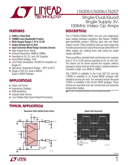
datasheet_lmsz620
- 格式:pdf
- 大小:415.04 KB
- 文档页数:4
Laser Wavelength Beam Divergence 6)
1) First, Last, or Alternating Target Mode selectable. 2) Typical values under average conditions. Maximum range
The following conditions are assumed: Flat target larger than footprint of laser beam, perpendicular angle of incidence, average brightness
Maximum Measurement Range [m] wet ice
2
Principle of Scanner Operation & Dimensional Drawings
The range finder electronics of the 3D laser scanner RIEGL LMS-Z620 are optimized in order to meet the requirements of high speed scanning (high laser repetition rate, fast signal processing, and high speed data interface).
visit our webpage
®
LASER MEASUREMENT SYSTEMS
System Key Performance Data
Scanner Hardware LMS-Z620
allows high-speed, high resolution and accurate 3D measurements · Range up to 2000 m @ Laser Class 1 · Repeatability up to 5 mm · Measurement rate up to 11000 pts/sec · Field of View up to 80° x 360° · TCP/IP data interface, allowing easy wireless data transmission · Operable with any standard PC or Notebook · Fully portable, rugged & robust
vertical scanning
range up to 80°
front pane
Scandata: RANGE, ANGLE, SIGNAL AMPLITUDE, and optional TIMESTAMP are transmitted to a laptop via TCP/IP Ethernet Interface. Camera data is fed into the same laptop via USB/firewire interface.
Max. Measurement Range 2) for natural targets, ρ ≥ 80 % for natural targets, ρ ≥ 10 %
Minimum Range Accuracy 3) 5) Repeatability 4) 5) Measurement Rate
Extra Long Range & High Accuracy 3D Terrestrial Laser Scanner
LMS-Z620
The terrestrial laser scanner system RIEGL® LMS-Z620 consists of a high performance long-range 3D scanner, the accompanying operating and processing software RiSCAN PRO, and a calibrated and accurately orientated and mounted high-resolution digital camera. The system provides data which lends itself to automatic or semiautomatic processing of scan- and image data to generate products such as textured triangulated surfaces and high resolution panorama images as a basis for e.g., geotechnical analysis and mining assessment. The RIEGL LMS-Z620 is a rugged and fully portable sensor especially designed for the rapid acquisition of high-quality three dimensional images even under highly demanding environmental conditions, providing a unique and unrivalled combination of a wide field-of-view, high maximum range, and fast data acquisition. A standard Windows notebook and the bundled software package RiSCAN PRO enable the user to instantly acquire high-quality 3D data in the field and provide a variety of registration, post processing and export functions.
2100 2000 1900 1800 1700 1600 1500 1400 1300 1200 1100 1000
0 0
standard clear atmosphere: visibility 23km clear atmosphere: visibility 15km light haze: visibility 8km medium haze: visibility 5km
The combination of the key components Scanner, Software and Camera results in
· Automatic generation of high resolution textured meshes · Online position and distance measurements · Photorealistic 3D reconstruction · Online setting of any virtual point of view · Exact identification of details
dry snow coniferous trees
dry asphalt deciduous trees
terra cotta cliffs, sand, masonry white plaster work, limestone
Maximum Measurement Range RIEGL LMS-Z620
side view
The vertical deflection ("line scan") of the laser beam is realized by a polygon with a number of reflective surfaces. For high scanning rates and/or a vertical scan angle of θ up to 80°, the polygonal mirror continuously rotates at an adjustable speed. For slow scanning rates and/or small scanning angles, it linearly oscillates up and down. The horizontal scan ("frame scan") is realized by rotating the complete optical head up to 360°.
bottom view
M8 thread (6x) for mounting
ON / OFF push button
∅ 180 203
moving part
463
fixed part
∅ 210
carrying handle
mounting rail
horizontal scanning range up to full 360°
removeable adapter for vertical
tripod mounting
The RiSCAN PRO software allows the operator to perform a large number of tasks including sensor configuration, data acquisition, data visualization, data manipulation, and data archiving. RiSCAN PRO runs on the platforms Windows XP Professional, Windows VISTA Professional, and Windows 7 Professional.
• Topography & Mining • Monitoring & Civil Engineering • Archaeology & Cultural
1) First, Last, or Alternating Target Mode selectable. 2) Typical values under average conditions. Maximum range
The following conditions are assumed: Flat target larger than footprint of laser beam, perpendicular angle of incidence, average brightness
Maximum Measurement Range [m] wet ice
2
Principle of Scanner Operation & Dimensional Drawings
The range finder electronics of the 3D laser scanner RIEGL LMS-Z620 are optimized in order to meet the requirements of high speed scanning (high laser repetition rate, fast signal processing, and high speed data interface).
visit our webpage
®
LASER MEASUREMENT SYSTEMS
System Key Performance Data
Scanner Hardware LMS-Z620
allows high-speed, high resolution and accurate 3D measurements · Range up to 2000 m @ Laser Class 1 · Repeatability up to 5 mm · Measurement rate up to 11000 pts/sec · Field of View up to 80° x 360° · TCP/IP data interface, allowing easy wireless data transmission · Operable with any standard PC or Notebook · Fully portable, rugged & robust
vertical scanning
range up to 80°
front pane
Scandata: RANGE, ANGLE, SIGNAL AMPLITUDE, and optional TIMESTAMP are transmitted to a laptop via TCP/IP Ethernet Interface. Camera data is fed into the same laptop via USB/firewire interface.
Max. Measurement Range 2) for natural targets, ρ ≥ 80 % for natural targets, ρ ≥ 10 %
Minimum Range Accuracy 3) 5) Repeatability 4) 5) Measurement Rate
Extra Long Range & High Accuracy 3D Terrestrial Laser Scanner
LMS-Z620
The terrestrial laser scanner system RIEGL® LMS-Z620 consists of a high performance long-range 3D scanner, the accompanying operating and processing software RiSCAN PRO, and a calibrated and accurately orientated and mounted high-resolution digital camera. The system provides data which lends itself to automatic or semiautomatic processing of scan- and image data to generate products such as textured triangulated surfaces and high resolution panorama images as a basis for e.g., geotechnical analysis and mining assessment. The RIEGL LMS-Z620 is a rugged and fully portable sensor especially designed for the rapid acquisition of high-quality three dimensional images even under highly demanding environmental conditions, providing a unique and unrivalled combination of a wide field-of-view, high maximum range, and fast data acquisition. A standard Windows notebook and the bundled software package RiSCAN PRO enable the user to instantly acquire high-quality 3D data in the field and provide a variety of registration, post processing and export functions.
2100 2000 1900 1800 1700 1600 1500 1400 1300 1200 1100 1000
0 0
standard clear atmosphere: visibility 23km clear atmosphere: visibility 15km light haze: visibility 8km medium haze: visibility 5km
The combination of the key components Scanner, Software and Camera results in
· Automatic generation of high resolution textured meshes · Online position and distance measurements · Photorealistic 3D reconstruction · Online setting of any virtual point of view · Exact identification of details
dry snow coniferous trees
dry asphalt deciduous trees
terra cotta cliffs, sand, masonry white plaster work, limestone
Maximum Measurement Range RIEGL LMS-Z620
side view
The vertical deflection ("line scan") of the laser beam is realized by a polygon with a number of reflective surfaces. For high scanning rates and/or a vertical scan angle of θ up to 80°, the polygonal mirror continuously rotates at an adjustable speed. For slow scanning rates and/or small scanning angles, it linearly oscillates up and down. The horizontal scan ("frame scan") is realized by rotating the complete optical head up to 360°.
bottom view
M8 thread (6x) for mounting
ON / OFF push button
∅ 180 203
moving part
463
fixed part
∅ 210
carrying handle
mounting rail
horizontal scanning range up to full 360°
removeable adapter for vertical
tripod mounting
The RiSCAN PRO software allows the operator to perform a large number of tasks including sensor configuration, data acquisition, data visualization, data manipulation, and data archiving. RiSCAN PRO runs on the platforms Windows XP Professional, Windows VISTA Professional, and Windows 7 Professional.
• Topography & Mining • Monitoring & Civil Engineering • Archaeology & Cultural