MTKG modem 配置
- 格式:doc
- 大小:113.50 KB
- 文档页数:9

Wireless-GBroadband Routerwith 2 Phone PortsModel No: WRP400of their respective holders.Chapter 1: Product Overview 4 Front Panel. . . . . . . . . . . . . . . . . . . . . . . . . . . . . . . . . . . . . . . . . . . . . . . . . . 4 Back Panel . . . . . . . . . . . . . . . . . . . . . . . . . . . . . . . . . . . . . . . . . . . . . . . . . . 4 Side Panel . . . . . . . . . . . . . . . . . . . . . . . . . . . . . . . . . . . . . . . . . . . . . . . . . . 5 Placement Positions. . . . . . . . . . . . . . . . . . . . . . . . . . . . . . . . . . . . . . . . . . . . 5 Chapter 2: Wireless Security Checklist 7 General Network Security Guidelines. . . . . . . . . . . . . . . . . . . . . . . . . . . . . . . . . 7 Additional Security Tips . . . . . . . . . . . . . . . . . . . . . . . . . . . . . . . . . . . . . . . . . 7 Chapter 3: Advanced Configuration 8 Setup > Basic Setup . . . . . . . . . . . . . . . . . . . . . . . . . . . . . . . . . . . . . . . . . . . . 8 Setup > DDNS. . . . . . . . . . . . . . . . . . . . . . . . . . . . . . . . . . . . . . . . . . . . . . . .12 Setup > MAC Address Clone. . . . . . . . . . . . . . . . . . . . . . . . . . . . . . . . . . . . . . .13 Setup > Advanced Routing . . . . . . . . . . . . . . . . . . . . . . . . . . . . . . . . . . . . . . .13 Wireless > Basic Wireless Settings . . . . . . . . . . . . . . . . . . . . . . . . . . . . . . . . . . .14 Wireless > Wireless Security . . . . . . . . . . . . . . . . . . . . . . . . . . . . . . . . . . . . . . .15 Wireless > Wireless MAC Filter. . . . . . . . . . . . . . . . . . . . . . . . . . . . . . . . . . . . . .17 Wireless > Advanced Wireless Settings . . . . . . . . . . . . . . . . . . . . . . . . . . . . . . . .17 Security > Firewall . . . . . . . . . . . . . . . . . . . . . . . . . . . . . . . . . . . . . . . . . . . . .18 Security > VPN Passthrough. . . . . . . . . . . . . . . . . . . . . . . . . . . . . . . . . . . . . . .19 Access Restrictions > Internet Access . . . . . . . . . . . . . . . . . . . . . . . . . . . . . . . . .19 Applications and Gaming > Single Port Forwarding. . . . . . . . . . . . . . . . . . . . . . . .20 Applications and Gaming > Port Range Forward. . . . . . . . . . . . . . . . . . . . . . . . . .21 Applications & Gaming > Port Range Triggering . . . . . . . . . . . . . . . . . . . . . . . . . .22 Applications and Gaming > DMZ . . . . . . . . . . . . . . . . . . . . . . . . . . . . . . . . . . .22 Applications and Gaming > QoS . . . . . . . . . . . . . . . . . . . . . . . . . . . . . . . . . . . .23 Administration > Management. . . . . . . . . . . . . . . . . . . . . . . . . . . . . . . . . . . . .24 Administration > Log . . . . . . . . . . . . . . . . . . . . . . . . . . . . . . . . . . . . . . . . . . .26 Administration > Diagnostics . . . . . . . . . . . . . . . . . . . . . . . . . . . . . . . . . . . . . .26 Administration > Factory Defaults. . . . . . . . . . . . . . . . . . . . . . . . . . . . . . . . . . .27 Administration > Firmware Upgrade . . . . . . . . . . . . . . . . . . . . . . . . . . . . . . . . .28 Administration > Config Management . . . . . . . . . . . . . . . . . . . . . . . . . . . . . . . .28 Status > Router . . . . . . . . . . . . . . . . . . . . . . . . . . . . . . . . . . . . . . . . . . . . . . .28 Status > Local Network . . . . . . . . . . . . . . . . . . . . . . . . . . . . . . . . . . . . . . . . . .29 Status > Wireless Network . . . . . . . . . . . . . . . . . . . . . . . . . . . . . . . . . . . . . . . .30 Access to the Voice Screens . . . . . . . . . . . . . . . . . . . . . . . . . . . . . . . . . . . . . . .30 Voice > Info . . . . . . . . . . . . . . . . . . . . . . . . . . . . . . . . . . . . . . . . . . . . . . . . .30 Voice > System . . . . . . . . . . . . . . . . . . . . . . . . . . . . . . . . . . . . . . . . . . . . . . .32 Voice > User 1/2 . . . . . . . . . . . . . . . . . . . . . . . . . . . . . . . . . . . . . . . . . . . . . .32 Voice > Admin Login . . . . . . . . . . . . . . . . . . . . . . . . . . . . . . . . . . . . . . . . . . .33Chapter 4: Interactive Voice Response Menu 34 Overview. . . . . . . . . . . . . . . . . . . . . . . . . . . . . . . . . . . . . . . . . . . . . . . . . . .34 Menu Commands . . . . . . . . . . . . . . . . . . . . . . . . . . . . . . . . . . . . . . . . . . . . .34 Appendix A: Troubleshooting 35 Appendix B: Specifications 37 Appendix C: Warranty Information 39 Appendix D: Regulatory Information 40 FCC Statement . . . . . . . . . . . . . . . . . . . . . . . . . . . . . . . . . . . . . . . . . . . . . . .40 FCC Radiation Exposure Statement . . . . . . . . . . . . . . . . . . . . . . . . . . . . . . . . . .40 Safety Notices and Information. . . . . . . . . . . . . . . . . . . . . . . . . . . . . . . . . . . . .40 Industry Canada Statement . . . . . . . . . . . . . . . . . . . . . . . . . . . . . . . . . . . . . . .40 Avis d’Industrie Canada. . . . . . . . . . . . . . . . . . . . . . . . . . . . . . . . . . . . . . . . . .41 Wireless Disclaimer . . . . . . . . . . . . . . . . . . . . . . . . . . . . . . . . . . . . . . . . . . . .41 Avis de non-responsabilité concernant les appareils sans fil . . . . . . . . . . . . . . . . . .41 Telepermit Statement. . . . . . . . . . . . . . . . . . . . . . . . . . . . . . . . . . . . . . . . . . .41 Declaration of Conformity with Regard to EU Directive 1999/5/EC (R&TTE Directive) . .42 CE Marking . . . . . . . . . . . . . . . . . . . . . . . . . . . . . . . . . . . . . . . . . . . . . . . . .43 National Restrictions . . . . . . . . . . . . . . . . . . . . . . . . . . . . . . . . . . . . . . . . . . .43 Product Usage Restrictions . . . . . . . . . . . . . . . . . . . . . . . . . . . . . . . . . . . . . . .44 Technical Documents on /international . . . . . . . . . . . . . . . . . . . .44 User Information for Consumer Products Covered by EU Directive 2002/96/EC on WasteElectric and Electronic Equipment (WEEE). . . . . . . . . . . . . . . . . . . . . . . . . . . . . .45to the corresponding port on the Router’s back panel. The LED slowly flashes when voicemail messages are waiting.Phone 1-2analog telephones to the Router.sure that the wall you use is smooth, flat, dry, and sturdy. Also make sure the location is within reach of an electrical outlet.Drill two holes into the wall. Make sure the holes are 60 mm (2.36 inches) apart.2.1.specify the MAC address of each computer in your home so that only those computers can access your wireless network.Setup > Basic SetupThe first screen that appears is the Basic Setup screen. This allows you to change the Router’s general settings.Internet Connection Type > Automatic Configuration - DHCPattempt to access the Internet again. To use this option, select Connect on Demand. In the Max Idle Time field, enter the number of minutes you want to have elapsed before your Internet connection terminates. The default Max Idle Time is minutes.default value is 30 seconds.Connect on Demand: Max Idle T me You can configure the Router to cut the Internet connection after it has been inactive for a specified period of time (Max Idle Time). If network connected to the Router’s Ethernet ports. W ireless setup is performed through the Wireless tab.DHCP ReservationTime SettingT me Zone Select the time zone in which your network functions from this drop-down menu.Enabled/D sabled To have the MAC address cloned, select Enabled.MAC Address Enter the MAC address registered with your ISP here.Static RoutingA static route is a pre-determined pathway that network information must travel to reach a specific host or network.Select a SSID Select the appropriate SSID. (If you enabled the second wireless network on the Basic Wireless Settings screen, then set up wireless security for each SSID.)methods, TKIP and AES, with dynamic encryption keys. Select the type of algorithm, AES or TKIP + AES. The default is TKIP + AES.WPA Shared Key Enter a WPA Shared Key of 8-63 characters.10 hex d g ts.Passphrase Enter a Passphrase to automatically generateWEP keys. Then click Generate.address. This button is selected by default.Perm t Select this to allow wireless access by MAC address. This button is not selected by default.Wireless > Advanced Wireless SettingsClick Save Sett ngs to apply your changes, or click CancelChanges to cancel your changes.sites created using this programming language. Selectthis feature to enable Java filtering. Deselect the featureto allow Java usage.access, designated services, and websites during specific days and times.depending on whether you want to block or allow Internet access for the computers you listed on the Listof PCs screen.The Port Range Forward screen allows you to set up public services on your network, such as web servers, ftp servers, e-mail servers, or other specialized Internet applications. (Specialized Internet applications are any applications Click Save Sett ngs to apply your changes, or click Cancel Changes to cancel your changes.one PC. The Port Range Forwarding feature is more secure because it only opens the ports you want to have opened, while DMZ hosting opens all the ports of one computer, exposing the computer to the Internet. Address, and MAC Address. T o select a DHCP client, click Select. To retrieve the most up-to-date information, click Refresh. To exit this screen and return to the DMZ screen, click Close.keep the default, Auto. To manually set the maximum,Remote AccessRemote Management To permit remote access of the Router, from outside the local network, select Enabled. Otherwise, keep the default, D sabled.RTSP Support If you are experience issues with video-on-demand applications, select Enabled to improve multimedia transmissions. Using this option, the Router will establish channels with the Real Time Streamingare adm n). If the defaults do not work, contact your ITSP for more information.Status > RouterThe Router screen displays information about the Router.The DHCP Client Table lists computers and other devices that have been assigned IP addresses by the Router. The list can be sorted by Client Name, IP Address, Interface, MAC Address, and Expires Time(how much time is left for the current IP address). Tothen you will be asked to enter it before the Info screen is displayed.The Admin Login allows access to more advanced settings. To access administrative screens, click Adm n Log n, and displayed.Software Vers on The version number of the Router software is displayed.Message Wa t ng This indicates whether you have new voicemail waiting.Call Back Act ve This indicates whether a call back request is in progress.received is displayed.Call 1/2 Mapped RTP Port The number of the NAT mapped RTP port is displayed.Forward Last activation code is used.Cfwd Last Dest Enter the forward number for the CfwdLast Caller feature.Cblk R ng Splash Len Enter the duration of the ring splash when a call is blocked. The range is 0 to 10.0seconds. The default is 0.OperationMAC Address Cloning Port Forwarding Syslog & Debug Server Records Per Line and Purpose ConfigurableSyslog and Debug Options(Average)Power Adapter: 100-240V - 50-60Hz(26-34VA) AC Input, 1.8 m Cordattacking networks, Linksys does not warrant that the Product will be free of vulnerability to intrusion or attack.Safety Notices and InformationCaution: To reduce the risk of fire, use only No.26 AWG or larger telecommunication line cord.•This transmitter must not be co-located or operating in conjunction with any other antenna or transmitter.In Denmark, the band 5150 - 5350 MHz is also allowed for outdoor usage.I Danmark må frekvensbåndet 5150 - 5350 også anvendesudendørs.The regulatory limits for maximum output power are specified in EIRP . The EIRP level of a device can be calculated by adding the gain of the antenna used (specified in dBi) to the output power available at the connector (specified in dBm).2.please contact your local sales office or visit www.l / nternat onal7102310A-JL。
M T K平台m o d e m配置先从modem配置表里了解一下每一个文件夹对应哪个频段的配置其他没有标记的,目前我们是用不到的,也不要去修改里面的参数。
打开每一个需要修改的文件夹,可以看到三个子文件夹,类似下图:我们只需要修改上面框选里面的文件夹里面的选项即可。
进入到文件夹里面,发现有好几个文件,我们只需要修改下面标红的两个就可以了,一般都是**_mipi.h和**_rf.h文件各个文件夹里面文件详细说明如下图:了解了上面文件说明后,下面开始讲具体参数配置。
一、mmll_rfUSID配置以及修改由于我们目前使用到的SKY的PA和开关,所以他们两个的USID是一样的,出厂默认都是OxF,按照常理来讲,由于PA和开关挂在不同的MIPI通路上,是不会有地址冲突的问题,但是目前MT6735平台存在弱4G信号下,切不回2G通话,也就是有时候打不进来电话,所以需要将这两个设备的USID改成不一样,修改PA和开关都可以,下面示例修改PA的USID。
首先打开SKY77643的规格书,找到这个位置稍后将会用到里面的ProductID和ManufacturerID然后在mmll_rf文件夹里面打开这两个文件夹在mml1_custom_mipi.c文件里面找到这个位置,按照上面的描述修改相应的值后面的newUSID可以修改为0x1~0xE之间的一个,在mml1_custom_mipi.h文件里面对应修改就可以了,由于我们修改的是PA,所以在portsel下面需要选取MIPI_PORT0,如果是开关的话,就需要对应修改为MIPI_PORT1。
至于在这里选取修改的USID是PA0还是PA1,ASM0还是ASM1,可以从后面的文件里面看出来。
比如在4G里面的lte_custom_mipi.c文件里面,可以看到在TPC这里会有一个USID的调用。
这里可以看到,在同一个文件里面对同一个PA可能会有两个USID的调用,主要因为这个modem沿用了phase-1设计的模板,很多东西没有和phase-2设计选用的PA对应上来,我们目前的设计中,FDD和TDD已经做到一个PA里面去了,所以USID应该是要一致的,所以我们后来把所有用到PA1的地方全部改为了PA0。
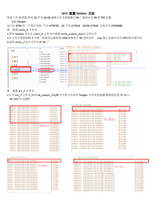
准备工作:原理图,所用2G开关,4G PA,通路小开关的规格书,PA厂提供对应PA的TPC表格原始Modem如下以6739的一个项目为例; 平台:MT6739 2G开关:VC7916 4G PA:VC7643 分集开关:MXD8680❖配置mml1_rf文件夹1,拿到Modem首先在mml1_rf文件夹中找到mml1_custom_mipi.h文件打开2,在文件中找到如图3中那一段来设定器件的USID,如果两个PA没挂在同一mipi线上直接可以用MTK默认就可以3,这样mml1_rf这个文件夹就OK了❖配置el1_rf文件夹1,打开el1_rf文件夹,找到lte_custom_rf.h(39平台的文件放在Toolgen文件夹里面)配置频段信息;TX端口;RX;通路开关逻辑.开关逻辑以B1为例:通过原理图看到B1连接的8680开关的RF8脚,开关的V3,V2,V1分别连接的BPI_BUS6,BPI_BUS7,BPI_BUS8,通过查看8680开关的规格书得到RF8的逻辑是V1=1,V2=1,V3=1计算出来的二进制是111000000换算16进制是1C0,所以如上图B1的逻辑配置是0X000001C0;其它频段配置同理;到这里lte_custom_rf.h文件配置完成2,打开lte_custom_mipi.c文件配置RX EVENT; TX EVENT; RX DATA; TX DATA; TPC.RX EVENT配置,如图1 BAND1 RX通路上的没有开关所以开和关都只用了1个步骤,所以RX ON配置是(0,0)RX OFF是(1,1); 图2 BAND40 RX 通路除了2G开关外,还经过了4G PA的内部开关,所以B40 的RX开关步骤比较多: (0,0)=2G开关ON, (1,1)=4G PA内部开关ON, (2,2)2G 开关OFF, (3,3)4G PA内部开关OFFRX DATA配置,RX DATA配置的步骤要用上面RX EVENT的步骤要一致;如图1是BAND的RX DATA. 图1 中的2G 开关ON,配置成0X18这个值是从原理图连接的端口和VC7916的规格书中得到图2 B40 的两配置的两个值0X02,和0X0D分别是从2G开关和4G PA的规格书中得到TX EVENT配置,如图1 的BAND 1 PA ON要三个步骤所以配置是(0,3); PA OFF 1个步骤配置是(4,4); 2G开关ON(5,5) 其它频段,同理配置就OKTX DATA配置, TX DATA的配置要和上面TX EVENT的步骤要对应得上;如上图步骤详解:0X00步骤配置为0X64,意思是配置PA的使用路径,B1连接的是MB4,通过PA规格书计算出来是64, 0X01步骤配置为(0X00)是PA 隔离的意思;0X02配置为(0XD0)是从规格书的0X02地址配置得到,意思是PA发射,如图第三步骤0X03配置为(0X00)也是为了隔离;第四步骤0X04配置为(0X00)意思为关闭PA,第五步骤0X05 配置为(0X18)意思是打开2G开关,从2G开关规格书得到这个值,如图注意:B39如果走的是2G 开关的通道,要在lte_custom_rf_tpc.h文件里面把PA模式设置为VPA_SOURCE_HW_VAPCB39走2G开关步骤详解:0X0 PA路径配置为(0X0F),这个值从2G开关规格书中得到,如图; 0X01这一步骤为PA的偏置电压,配置为0X88,是延用了SKY PA的配置,没有问题可以不用修改;TPC的配置, 以B1为例:0X0这一例配置为0X64对应的是B1 DATA路径上配置的0X64; 0X1这一例配置的值从PA规格书中的TPC表格得到,如图; 其它频段同理配置就可,到这里el1_rf 这个文件夹就配置OK了.❖ul1_rf文件夹配置1,打开ul1_rf文件夹,找到ul1d_custom_rf.h文件配置RX端口, TX端口,频段信息,BPI逻辑等.2,ul1d_custom_mipi.c配置,这个文件配置和LTE的是同理,也是要配置RX EVENT, TX EVENT, RX DATA, TX DATA, TPC这几项. RX EVENT,RX DATA,TX EVENT,TX DATA,TPC配置,如图配置的TPC是延用的SKY的TPC表,0X00配置为(0X64)表示PA路径,0X02配置为(0XD0)表示PA发射,同LET一样; 0X01和0X03配置如8功率等级配置为(0X77)和(0X88),这两个值可以从SKY的TPC配置表中得到,如图表格,其它功等级的TPC如表格类推就可! 至此ul1_rf文件夹配置完成!❖l1_rf文件夹配置1,打开l1_rf找到m12193.c文件,配置频段信息;2,l1d_custom_rf.h配置,在这个文件中配置RX端口, BPI逻辑;TX端口不用配置,在后面的l1d_custom_mipi.c文件定义就OK RX端口配置,BPI逻辑配置,3,l1d_custom_mipi.c配置,这个文件同样是要配置RX EVENT, TXEVENT, RX DATA, TX DATA, 和TPCRX EVENT,RX DATA,TX EVENT,TX DATA,DATA步骤详解:0X1C配置为(0X38)表示器件初始化; 0X00配置为(0X06)表示器件隔离,开关规格书上得到; 0X01配置为(0X86)表示TX偏置电压,从规格书中得到; 0X00配置为(GGE_MIPI_PA_G8)表示调制模式,不可修改; 0X1C配置为(0XB8)表示PA关闭TPC配置,TPC配置从规格书中得到值,如图到这里l1_rf文件夹配置完成.❖tl1_rf文件夹配置1,tl1d_custom_rf.h配置,这个文件主要配置,控制电压模式,RX 端口, TX端口,控制电压模式,2,tl1d_custom_mipi.h配置,这个文件主要配置,ASM和PA的USID, RX DATA, TX DATA, ASM和PA USIDRX DATA,RX ON配置为0X1C是从原理图上得到连接的是TRX12端口,规格书上0X1C,如图TX DATA,TX ON配置为(PA_FLAG_SetDefault)表示设置为默认值,调用下面的TPC参数.PA TPC,如图步骤详解:0X00配置为(0X0F)表示PA发射; 0X01配置为(0XF7)是表示PA偏置电压,根据实测值微调;高中低三段配置一样就行,到这里TDS部分就配置完成!❖cl1_rf文件夹配置1,c2k_custom_rf.h文件配置,这个文件主要配置,频段信息, RX 端口, TX端口, BPI逻辑现在新的MTK方案CDMA都是共用的FDD BAND5通道频段信息,RX 端口2,c2k_custom_mipi.c配置,这个文件要配置RX EVENT, TX EVENT, RX DATA, TX DATA,TPC RX EVENTRX DATARX DATA 详解,0X1C配置为(0X38)表示器件初始化,一般器件初始化都是0X380X00配置为(0X05)表示RX ON,这个值从2G开关规格书得到0X00配置为(0X00)表示PA 待命, 0X1C配置为(0XB8)表示器件关闭TX EVENTTX DATATX DATA步骤详解:0X1C配置为(0X38)表示器件初始化; 0X00配置为(0X3C)表示PA路径如图2; 0X01配置为(0X00)表示空闲待命状态; 0X02配置为(0X50)表示PA ON 如图3; 0X03配置为(0X00)表示空闲待命; 0X00配置为(0X00)表示PA OFF0X1C配置为(0X38)表示器件初始化; 0X00配置为(0X05)表示2G开关ON 如图4;TPC配置TPC的配置延用了SKY的TPC表格,只需要配置1和3寄存器就可,如图1; EVDO和TPC配置的1X一样就可,如图2到这里cl1_rf文件夹就配置完成了!。

GPRS模块上网操作流程一)AT指令设置部分1.AT+CSQ 检查信号强度若返回10—31,0之间的信号数字则继续,如果信号是99,99,则应该考虑不停的键入A/命令,不停的让模块去搜寻网络。
2.AT+CIMI 获得SIM卡IMSI,确认SIM卡是否插入。
3.AT+CREG? 若返回为0,1则可以,确认是否能登录到GPRS网络。
二)连接设置1.开始—控制面板—电话和调制解调器选项。
2.双击电话和调制解调器选项,点新建按钮然后在弹出的界面里输入相应地区的区号,例如郑州则输入0371,深圳则输入0755,点击确定。
如图所示:3.在电话和调制解调器选项界面里,点击上方的调制解调器,点添加按钮然后弹出如下一个界面,并在“不要检测我的调制解调器”前的小方框中打勾,如图所示:点击下一步按钮,并选择标准33600bps调制解调器,如下图所示:点下一步,如下图,选择COM1端口。
点下一步,系统正在安装调制解调器,最后点击完成。
安装完成之后会弹出如下一个界面:点属性按钮,弹出如下界面。
点上方的高级按钮,弹出如下界面。
在额外的初始化命令中输入一条AT+CGDCONT=1,"IP","CMNET" ,如下图所示。
点击确定按钮。
三)设置拨号网络。
电脑网络连接中,选择“创建一个新的连接”下一步“下一步”—“手动设置我的连接”下一步下一步下一步—下一步,最后点完成,此时会弹出如下一个界面。
用户名和密码不填,在拨号中输入*99***1#点拨号,如下图:点击拨号,如果调置正确,就能浏览网页了。
如果不能注册到计算机上,最好重启一下电脑。
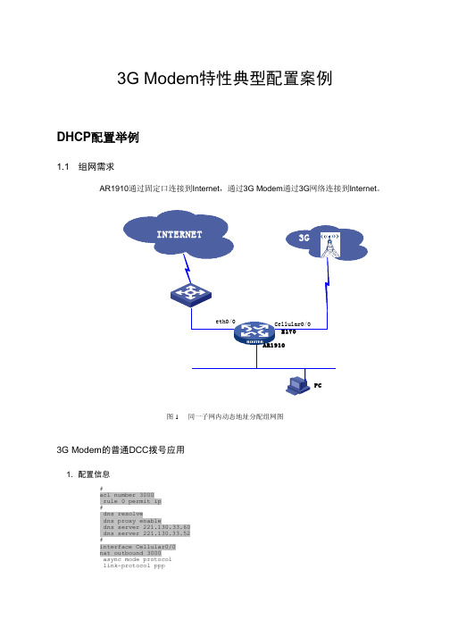
3G Modem特性典型配置案例DHCP配置举例1.1 组网需求AR1910通过固定口连接到Internet,通过3G Modem通过3G网络连接到Internet。
图 1 同一子网内动态地址分配组网图3G Modem的普通DCC拨号应用1. 配置信息#acl number 3000rule 0 permit ip#dns resolvedns proxy enabledns server 221.130.33.60dns server 221.130.33.52#interface Cellular0/0nat outbound 3000async mode protocollink-protocol pppppp ipcp dns requestip address ppp-negotiatedialer enable-circulardialer-group 1dialer timer idle 60dialer number *99##ip route-static 0.0.0.0 0.0.0.0 Cellular0/0#dialer-rule 1 ip permit#user-interface tty 1modem both#2. 主要配置步骤1) 配置感兴趣流量[H3C]dialer-rule 1 ip permit2) 配置modem允许呼出[H3C]user-interface tty 0[H3C-ui-tty0] modem both3) 配置cellular接口的拨号功能与NAT功能[H3C]interface Cellular0/0[H3C-Cellular0/0]async mode protocol[H3C-Cellular0/0]ip address ppp-negotiate[H3C-Cellular0/0]ppp ipcp dns request[H3C-Cellular0/0]dialer enable-circular[H3C-Cellular0/0]dialer-group 1[H3C-Cellular0/0]dialer timer idle 60[H3C-Cellular0/0]dialer number *99#4) 配置本地DNS解析与DNS代理功能[H3C]dns resolve[H3C]dns proxy enable[H3C]dns server 221.130.33.60[H3C]dns server 221.130.33.525) 配置ACL,并在Cellular接口上启用NAT[H3C]acl number 3000[H3C-acl-adv-3000]rule 0 permit ip[H3C-acl-adv-3000]interface Cellular0/0[H3C-Cellular0/0]nat outbound 30006) 配置静态路由[H3C]ip route-static 0.0.0.0 0.0.0.0 Cellular0/03. 验证步骤1) 查看3G Modem的状态信息<H3C>dis ce 0/0 allModem State:Hardware Information====================Modem Firmware Version = 11.304.17.00.00Hardware Version = CD96TCPUInternational Mobile Subscriber Identity (IMSI) = 460020263407632International Mobile Equipment Identity (IMEI) = 359298019050464Factory Serial Number (FSN) = EV5TAB2842800069Modem Status = OnlineProfile Information====================Profile 1 = ACTIVE--------PDP Type = IPv4, Header Compression = OFFData Compression = OFFAccess Point Name (APN) = 100Packet Session Status = Inactive* - Default profileNetwork Information===================Current Service Status = Service availableCurrent Service = CombinedPacket Service = AttachedPacket Session Status = InactiveCurrent Roaming Status = RoamingNetwork Selection Mode = ManualMobile Country Code (MCC) = 460Mobile Network Code (MNC) = 00Location Area Code (LAC) = 4318Cell ID = 25381Radio Information=================Current Band = ANYCurrent RSSI = -51 dBmModem Security Information==========================Card Holder Verification (CHV1) = DisabledSIM Status = OK<H3C>2) 没有呼叫时的接口状态:<H3C>dis int ceCellular0/0 current state: DOWNLine protocol current state: UP (spoofing)Description: Cellular0/0 InterfaceThe Maximum Transmit Unit is 1500, Hold timer is 10(sec)Internet protocol processing : disabledLink layer protocol is PPPLCP initialOutput queue : (Urgent queuing : Size/Length/Discards) 0/100/0Output queue : (Protocol queuing : Size/Length/Discards) 0/500/0Output queue : (FIFO queuing : Size/Length/Discards) 0/75/0Physical layer is asynchronous, Baudrate is 9600 bpsLast clearing of counters: NeverLast 5 seconds input rate 0.00 bytes/sec, 0 bits/sec, 0.00 packets/secLast 5 seconds output rate 0.00 bytes/sec, 0 bits/sec, 0.00 packets/secInput: 55 packets, 3961 bytes0 broadcasts, 0 multicasts0 errors, 0 runts, 0 giants0 CRC, 0 align errors, 0 overruns0 dribbles, 0 aborts, 0 no buffers0 frame errorsOutput:43 packets, 3140 bytes0 errors, 0 underruns, 0 collisions0 deferredDCD=DOWN DTR=DOWN DSR=DOWN RTS=DOWN CTS=DOWN<H3C>3) 触发拨号以及建立呼叫后的Modem状态与Cellular接口状态:<H3C> ping -c 1 PING (202.108.22.5):56 data bytes, press CTRL_C to break%Dec 2 10:26:19:650 2008 H3C IFNET/4/LINK UPDOWN:Cellular0/0: link status is UP%Dec 2 10:26:19:655 2008 H3C IFNET/4/UPDOWN:Line protocol on the interface Cellular0/0 is UP%Dec 2 10:26:20:229 2008 H3C IFNET/4/UPDOWN:Protocol PPP IPCP on the interface Cellular0/0 is UP*Dec 2 10:26:20:230 2008 H3C RM/3/RMDEBUG:Receive invalid vlink addr(0)Request time out--- ping statistics ---1 packet(s) transmitted0 packet(s) received100.00% packet loss<H3C> ping -c 1 PING (202.108.22.5):56 data bytes, press CTRL_C to breakReply from 202.108.22.5: bytes=56 Sequence=1 ttl=52 time=563 ms--- ping statistics ---1 packet(s) transmitted1 packet(s) received0.00% packet lossround-trip min/avg/max = 563/563/563 ms<H3C>dis cel 0/0 alModem State:Hardware Information====================Modem Firmware Version = 11.304.17.00.00Hardware Version = CD96TCPUInternational Mobile Subscriber Identity (IMSI) = 460020263407632International Mobile Equipment Identity (IMEI) = 359298019050464Factory Serial Number (FSN) = EV5TAB2842800069Modem Status = OnlineProfile Information====================Profile 1 = ACTIVE--------PDP Type = IPv4, Header Compression = OFFData Compression = OFFAccess Point Name (APN) = 100Packet Session Status = Active* - Default profileNetwork Information===================Current Service Status = Service availableCurrent Service = CombinedPacket Service = AttachedPacket Session Status = ActiveCurrent Roaming Status = RoamingNetwork Selection Mode = ManualMobile Country Code (MCC) = 460Mobile Network Code (MNC) = 00Location Area Code (LAC) = 4318Cell ID = 25381Radio Information=================Current Band = ANYCurrent RSSI = -51 dBmModem Security Information==========================Card Holder Verification (CHV1) = DisabledSIM Status = OK<H3C><H3C>dis int ceCellular0/0 current state: UPLine protocol current state: UP (spoofing)Description: Cellular0/0 InterfaceThe Maximum Transmit Unit is 1500, Hold timer is 10(sec)Internet Address is negotiated, 10.8.55.214/32Link layer protocol is PPPPrimary DNS address is 221.130.33.52,Secondary DNS address is 221.130.33.60 LCP opened, IPCP openedOutput queue : (Urgent queuing : Size/Length/Discards) 0/100/0Output queue : (Protocol queuing : Size/Length/Discards) 0/500/0Output queue : (FIFO queuing : Size/Length/Discards) 0/75/0Physical layer is asynchronous, Baudrate is 9600 bpsLast clearing of counters: NeverLast 5 seconds input rate 23.20 bytes/sec, 185 bits/sec, 0.40 packets/sec Last 5 seconds output rate 47.79 bytes/sec, 382 bits/sec, 0.60 packets/sec Input: 67 packets, 4606 bytes0 broadcasts, 0 multicasts0 errors, 0 runts, 0 giants0 CRC, 0 align errors, 0 overruns0 dribbles, 0 aborts, 0 no buffers0 frame errorsOutput:57 packets, 4095 bytes0 errors, 0 underruns, 0 collisions0 deferredDCD=DOWN DTR=UP DSR=DOWN RTS=UP CTS=DOWN<H3C>1.2 3G Modem作为GigabitEthernet0/1的备份接口1. 配置信息#dns resolvedns proxy enabledns server 221.130.33.60dns server 221.130.33.52#acl number 3000rule 0 permit ip#interface Cellular0/0async mode protocollink-protocol pppppp ipcp dns requestip address ppp-negotiatedialer enable-circulardialer-group 1dialer timer idle 60dialer number *99##interface GigabitEthernet0/1port link-mode routeip address 172.32.1.1 255.255.255.0standby interface Cellular0/0standby timer delay 10 10#ip route-static 0.0.0.0 0.0.0.0 Cellular0/0ip route-static 0.0.0.0 0.0.0.0 GigabitEthernet0/1#dialer-rule 1 ip permit#user-interface tty 1modem both2. 主要配置步骤1) 与3.3类似配置cellular接口的拨号功能、NAT、DNS与静态路由等[H3C]dns resolve[H3C]dns proxy enable[H3C]dns server 221.130.33.60[H3C]dns server 221.130.33.52[H3C]dialer-rule 1 ip permit[H3C]user-interface tty 0[H3C-ui-tty0] modem both[H3C-ui-tty0] quit[H3C]acl number 3000[H3C-acl-adv-3000]rule 0 permit ip[H3C-acl-adv-3000]quit[H3C]ip route-static 0.0.0.0 0.0.0.0 Cellular0/0[H3C]ip route-static 0.0.0.0 0.0.0.0 GigabitEthernet0/1[H3C]interface Cellular0/0[H3C-Cellular0/0]async mode protocol[H3C-Cellular0/0]ip address ppp-negotiate[H3C-Cellular0/0]nat outbound 3000[H3C-Cellular0/0]ppp ipcp dns request[H3C-Cellular0/0]dialer enable-circular[H3C-Cellular0/0]dialer-group 1[H3C-Cellular0/0]dialer timer idle 60[H3C-Cellular0/0]dialer number *99#2) 在主接口上配置地址,并指定备份口为cellular0/0。

MTK手机MODEM上网操作指南(适用于MTK平台)第一步:开通 GPRS 功能确定您的SIM卡开通了GPRS功能和手机互联网业务,如果没有开通,可拨打相应运营商电话(如:移动10086)申请开通或到当地营业厅开通。
第二步:连接PC 和手机(USB Modem 驱动程序安装详见附件)将随机所配的数据线插入PC端的某个USB端口,将手机连接至数据线另一端,在手机上的“USB设定”界面选择“串口”。
第三步:查看COM 口点击“我的电脑”右键中的“属性” —→ 选择“硬件”—→选择“设备管理器”—→“端口”查看此设备使用的端口号。
如下图:第五步:Modem 属性设置点击“属性”—→选择“高级”功能项,在额外设置中输入AT 命令:AT+CGDCONT=1,"IP","CMNET","",0,0 ,然后点击“更改默认首选项”。
具体设置如下图示:第六步:新建拨号连接:新建一个使用上面 Modem 的拨号连接:在“控制面板”—“网络连接”界面,点击“创建一个新的连接”,创建步骤如以下图示:第七步:设置拨号连接:打开新建的拨号连接,用户名和密码都空着,拨号号码为*99#;点击“属性”,具体设置步骤如以下图示:第八步:拨号:在拨号窗口点击“拨号”,如下图(23)所示:拨号成功,电脑会跳出连接成功的提示,另可查看到如下图所示的拨号连接状态。
此时您就可以利用手机提供的MODEM 功能享受上网冲浪了。
注:以上示例是基于 Windows XP 操作系统的,Windows 2000 设置步骤与XP 一致。
附:USB 转串口驱动安装过程:第一步:将相应机型的 PC 同步软件解压保存在电脑上第二步:用数据线连接 PC 和手机,然后依照电脑提示安装USB 转串口驱动步骤 1:将随机所配的数据线插入PC 端的某个USB 端口,将手机连接至数据线另一端,在手机上的“USB 设定”界面选择“串口”。
MTK平台兼容多个G_SENSOR的调试1. 修改mediatek/config/project_name/projectconfig.mkCUSTOM_KERNEL_ACCELEROMETER=bma250_auto mc3xxx_autoMTK_AUTO_DETECT_ACCELEROMETER=yes2. 若已经调试好的bma250_auto mc3xxx_auto 只要直接配置就可以3. 若没有需将已经调试OK 的bma250和mc3xxx文件夹名字重命名为bma250_auto和 mc3xxx_automediatek/custom/common/kernel/accelerometer/bma250_automediatek/custom/common/kernel/accelerometer/mc3xxx_automediatek/custom/project_name/kernel/accelerometer/bma250_automediatek/custom/project_name/kernel/accelerometer/mc3xxx_auto3. 需修改bma250.c和 mc3xxx.c driver文件mediatek/custom/common/kernel/accelerometer/bma250_auto/bma250.cmediatek/custom/common/kernel/accelerometer/mc3xxx_auto/mc3xxx.c以bma250为例:(1)在代码文件靠前部分添加以下函数的声明static int bma250_local_init(void);static int bma250_remove(void);static int bma250_init_flag = -1;(2)增加定义或者打开定义static struct sensor_init_info bma250_init_info = {.name = "bma250",.init = bma250_local_init,.uninit = bma250_remove,}(3)重命名函数gsensor_operate为bma250_operateint gsensor_operate(void* self, uint32_t command, void* buff_in, int size_in,void* buff_out, int size_out, int* actualout)修改为int bma250_operate(void* self, uint32_t command, void* buff_in, intsize_in,void* buff_out, int size_out, int* actualout)(4) 修改相应的结构体static int bma250_i2c_probe(struct i2c_client *client, const structi2c_device_id *id)函数中sobj.sensor_operate = gsensor_operate;修改为:sobj.sensor_operate = bma250_operate;(5)将文件中所有的bma250_gsensor_driver.driver改为bma250_init_info.platform_diver_addr-> driverif(err = bma250_create_attr(&bma250_gsensor_driver.driver))替换为if(err=bma250_create_attr(&bma250_init_info.platform_diver_addr-> driver))(6)增加或者打开bma250_local_init和bma250_remove函数定义static int bma250_local_init(void){struct acc_hw *hw = get_cust_acc_hw();GSE_FUN();BMA250_power(hw, 1);if(i2c_add_driver(&bma250_i2c_driver)){GSE_ERR("add driver error\n");return -1;}if(-1 == bma250_init_flag){return -1;}}static int bma250_remove(void){struct acc_hw *hw = get_cust_acc_hw();GSE_FUN();BMA250_power(hw, 0);i2c_del_driver(&bma250_i2c_driver);return 0;}(7)在static int __init bma250_init(void) 中使用hwmsen_gsensor_add(&bma250_init_info);替换if(platform_driver_register(&bma250_gsensor_driver)){GSE_ERR("failed to register driver");return -ENODEV;}4. 如下修改mediatek/custom/project_name/kernel/accelerometer/bma250_auto/cust_a cc.c#include <linux/types.h>#include <cust_acc.h>#include <mach/mt_pm_ldo.h>/*------------------------------------------------------------*/int cust_acc_power(struct acc_hw *hw, unsigned int on, char* devname) {if (hw->power_id == MT65XX_POWER_NONE)return 0;if (on)return hwPowerOn(hw->power_id, hw->power_vol, devname);elsereturn hwPowerDown(hw->power_id, devname);}static struct acc_hw cust_acc_hw = {.i2c_num = 1,.direction =1,// 6,.power_id = MT65XX_POWER_NONE, /*!< LDO is not used */.power_vol= VOL_DEFAULT, /*!< LDO is not used */.firlen = 16, /*!< don't enable low pass fileter */.power =cust_acc_power,};struct acc_hw* get_cust_acc_hw(void){return & cust_acc_hw;}。
MTK平台modem 配置先从modem配置表里了解一下每一个文件夹对应哪个频段的配置其他没有标记的,目前我们是用不到的,也不要去修改里面的参数。
打开每一个需要修改的文件夹,可以看到三个子文件夹,类似下图:我们只需要修改上面框选里面的文件夹里面的选项即可。
进入到文件夹里面,发现有好几个文件,我们只需要修改下面标红的两个就可以了,一般都是**_mipi.h和**_rf.h文件各个文件夹里面文件详细说明如下图:了解了上面文件说明后,下面开始讲具体参数配置。
一、mmll_rf USID配置以及修改由于我们目前使用到的SKY的PA和开关,所以他们两个的USID是一样的,出厂默认都是OxF,按照常理来讲,由于PA和开关挂在不同的MIPI通路上,是不会有地址冲突的问题,但是目前MT6735平台存在弱4G信号下,切不回2G通话,也就是有时候打不进来电话,所以需要将这两个设备的USID改成不一样,修改PA和开关都可以,下面示例修改PA 的USID。
首先打开SKY77643的规格书,找到这个位置稍后将会用到里面的Product ID和Manufacturer ID然后在mmll_rf文件夹里面打开这两个文件夹在mml1_custom_mipi.c文件里面找到这个位置,按照上面的描述修改相应的值后面的new USID可以修改为0x1~0xE之间的一个,在mml1_custom_mipi.h文件里面对应修改就可以了,由于我们修改的是PA,所以在port sel 下面需要选取MIPI_PORT0,如果是开关的话,就需要对应修改为MIPI_PORT1。
至于在这里选取修改的USID是PA0还是PA1,ASM0还是ASM1,可以从后面的文件里面看出来。
比如在4G里面的lte_custom_mipi.c文件里面,可以看到在TPC这里会有一个USID的调用。
这里可以看到,在同一个文件里面对同一个PA可能会有两个USID的调用,主要因为这个modem沿用了phase-1设计的模板,很多东西没有和phase-2设计选用的PA对应上来,我们目前的设计中,FDD和TDD已经做到一个PA里面去了,所以USID应该是要一致的,所以我们后来把所有用到PA1的地方全部改为了PA0。
M T K平台m o d e m配置先从modem配置表里了解一下每一个文件夹对应哪个频段的配置其他没有标记的,目前我们是用不到的,也不要去修改里面的参数。
打开每一个需要修改的文件夹,可以看到三个子文件夹,类似下图:我们只需要修改上面框选里面的文件夹里面的选项即可。
进入到文件夹里面,发现有好几个文件,我们只需要修改下面标红的两个就可以了,一般都是**_mipi.h和**_rf.h文件各个文件夹里面文件详细说明如下图:了解了上面文件说明后,下面开始讲具体参数配置。
一、mmll_rfUSID配置以及修改由于我们目前使用到的SKY的PA和开关,所以他们两个的USID是一样的,出厂默认都是OxF,按照常理来讲,由于PA和开关挂在不同的MIPI通路上,是不会有地址冲突的问题,但是目前MT6735平台存在弱4G信号下,切不回2G 通话,也就是有时候打不进来电话,所以需要将这两个设备的USID改成不一样,修改PA和开关都可以,下面示例修改PA的USID。
首先打开SKY77643的规格书,找到这个位置稍后将会用到里面的ProductID和ManufacturerID然后在mmll_rf文件夹里面打开这两个文件夹在mml1_custom_mipi.c文件里面找到这个位置,按照上面的描述修改相应的值后面的newUSID可以修改为0x1~0xE之间的一个,在mml1_custom_mipi.h文件里面对应修改就可以了,由于我们修改的是PA,所以在portsel下面需要选取MIPI_PORT0,如果是开关的话,就需要对应修改为MIPI_PORT1。
至于在这里选取修改的USID是PA0还是PA1,ASM0还是ASM1,可以从后面的文件里面看出来。
比如在4G里面的lte_custom_mipi.c文件里面,可以看到在TPC这里会有一个USID的调用。
这里可以看到,在同一个文件里面对同一个PA可能会有两个USID的调用,主要因为这个modem沿用了phase-1设计的模板,很多东西没有和phase-2设计选用的PA对应上来,我们目前的设计中,FDD和TDD已经做到一个PA里面去了,所以USID应该是要一致的,所以我们后来把所有用到PA1的地方全部改为了PA0。
如上为修改USID内容。
二、l1_rf2G配置在配置寄存器之前,需要在l1d_custom_mipi.h里面确认mipi是否是打开的,在这个文件里面找到如下位置,这个值是1,就代表mipi是打开的,后面我们在配置的时候,只需要配置mipienable选项就可以了。
由于2G部分的发射走的是开关的通路,所以配置2G的时候,都需要在开关端配置完成。
在l1d_custom_mipi.c文件里面打开,先从大致的组织架构来讲,一般来说,在配寄存器之前,会有一个event事件让我们去定义,大致的意思是从第几行到第几行是什么功能,比如上图定义的是,从第0行到第1行是开关的预打开,这里的第0行就是我们实际的第1行,所以0~1,是需要占用两行去配置的。
从上面的event配置可以看出来,实际开关的打开时间在QB_MIPI_RX_ON1这一步。
上图是GSM接收的寄存器配置,在前面event事件定义的时候已经说过,第1,2行是开关的预打开,发射的时候也是一样的,所以,当我们看到0x1C这个寄存器的时候,我们都不用去修改,在上面的图中,一共有2次用到0x1C寄存器,第一次是初始化,最后一个是关闭作用,我们实际上用的到去配置的就是第三行,开关的00寄存器,这里拿SKY77916举例说明首先,可以从原理图上看出来,这里和3G的使用用的SKY77590类似,只不过是SKY77916外围可以提供14个TRX口让我们去做更多的频段上图是SKY77916的寄存器0的每一位说明,目前我们的modem里面都是用16进制的,所以转换成2进制,就一共有8位,特别注意的是第5位那里,0是正常增益,1是低增益,只针对高频,这里后面在B39的发射配置的时候会用到。
在控制开关打开关闭的时候,我们可以近似的把下面4:0这一行里面的值作为开关打开时候的值,例如,在GSM850RX配置的时候,TRX口用的是TRX4,所以此时GSM850接收寄存器0这里就需要配置为0x02,以上为GSMRX配置。
GSMTX配置和RX的event事件定义差不多在第1,2行还是开关的预打开,后面在开关PA打开的时候引入了寄存器1,寄存器用于设置PA的偏置电压GSM按照默认的去设置就好了,一般来说影响不大,在这里配置寄存器0的时候,和前面不一样,可以看到黄色箭头指向的位置,这里之前应该是一个数值,现在是GGE_MIPI_PA_G8这个宏,在紧跟着下面会有一个定义这里截取的是GSM850的配置,所以在GMSK调制发射的时候,值是0x0A,可以对比上面开关寄存器0的真值表,是LB_GMSK_TX,下面8PSK调制发射的时候,也就是我们平常说的EDGE,对应真值表是EDGE和线性发射,后面配置B34,B39的时候,它们的发射也需要选择此类发射。
照此类推可以配完GSM 其他频段。
另外在配置的时候,可能会看到有如下字符NOTCH_SWITCH,set0,set1,这些看到直接跳过,不需要配置。
接下来是配置l1d_custom_rf.h文件前面也有提到,我们在这里需要配置mipienable的情况,这里的配置是BPI 的配置,和我们之前的3G平台一样,我们只需要配置PR2和PT2后面的值就可以的,其他的可以不用管从35平台的原理图可以看出,BPI控制从0~27总共28个,所以转成16进制,一共就有7位,BPI0~3第最低位,4~7是倒数第2位,以此类推。
比如在B2,B3的接收位置,有一个开关去切换接收,它用的BPI口是10,又从开关特性知道,当BPI10=1的时候,主接收与B3的接收相通,所以在B3也就是DCS的PR2的地方,我们就需要配置成0x00000400,如果发射里面有开关,类似。
最后,就需要配置GSM的发射接收口了,在l1d_custom_rf.h文件下面可以找到这样两个位置上面是RX,下面是TX,还是和之前一样,这里只需要配置mipienable的选项,由于目前我们的项目接收都是和3G,4G(主集)双工器共用通路了,所以,这里接收我们只需要看Band,不用去分2,3,4G了,比如B2,在2,3,4G里面的接收口都会是IORX_MB1。
发射端口配置,根据原理图去匹配,一般来说,发射端口不会更改。
如上为整个2G配置方法。
三、3G配置(1)、WCDMA控制逻辑配置在ul1d_custom_mipi.h文件里面确认mipienable是否打开,默认都是打开的,可以确定下,不做修改。
打开ul1d_custom_mipi.c文件,先可以看到RX的event事件,这里比较简单,只有2行,第一行初始化,第二行打开开关对应下面的data控制和2G不一样,3G和4G是分段处理的,所以,所有的寄存器0都需要配成一样。
在WCDMA的TX配置的时候,首先看到event事件定义定义打开的其实也只有第一行也就是说,只有0x1C这里起了作用,后面的都是在关闭PA,在这里如果配置了PA的寄存器0和寄存器2也是没有关系的,通过实际测试发现,电流没有影响,但是为了安全起见,还是在TX里面把寄存器0,1,2,3的值都配置为0x00,发射的寄存器0,1,2,3的值,可以在后面TPC里面配置,同时,可以看到第6,7行是打开开关的,这里和前面一样,TRX口用的哪个开关就配置为其对应的值。
接下来是TPC里面的参数配置可以看到,最右边是有注释的,L7~L0,这是功率等级,L7是最大功率,从上往下依次减小。
这里PA是用的SKY77643,用B1举例说明一下每一个寄存器的配置。
先来了解一下SKY77643的内部架构图以及MT6169transceiver每个端口支持的频段,这里可以同理共用到SKY77643HB,MB,LB每组可以做到的频段。
从上面原理图对应的来看,B1使用的是MB1口,然后对应到SKY77643的真值表来配B1的TX,首先寄存器0直观给我们显示到的是用二进制的,所以,这个值是01001100,由于寄存器0的作用是打开PA,所以在选好端口发射后,需要让PAenable打开,对应到十六进制就是0x4C,接下来的寄存器1和寄存器3都是配置PA的偏置电压的,按照SKY提供的文档配置即可,这个可以参考文档:SkyworksMIPISettingforMTK。
如果存在ACLR比较差的情况,可以按照真值表将值改大,对应的电流也会变大,这个在4G上面可能需要改动,WCDMA 的时候一般按照默认的去写就好了。
对于寄存器2,它的作用是打开PA内部的开关,所以从上面的真值表对应下来就是10100000,即是0xA0。
对于寄存器0和2,7个等级都是一样的值。
接下来是ul1d_custom_rf.h文件我们进来也是可以看到BPI控制的,和之前一样还是配置PR2和PT2,这里多了一个RXD的选项,一般来说WCDMA的灵敏度比较高,可以不配置分集,如果遇到WCDMA灵敏度差的时候,可以尝试把这边的分集打开,如果有开关,就需要配置一下这里的BPI。
这里也是选取相应的端口即可。
在这个文件的最下面,可以看到如下的图这也就是定义我们打开哪几个WCDMA的频段,需要特别注意的是,前面3个是定义高频的,后面2个是定义低频的,要对应上频段去打开,以免出现一些不可预知的问题。
以上为WCDMA的整个配置。
(2)、TD-SCDMA控制逻辑配置在使用SKY77643+SKY77916的组合的时候,PA和开关都可以做B34,B39,目前为止我们只在L1上面做了TD-SCDMA,PA开关搭配是SKY77824+SKY77910,这个组合TD只能做在SKY77910上面,下面大致介绍一下配置方法,TD和其他几个制式配置方法有点不太一样,但是配置的地方不会太多。
打开tl1d_custom_mipi.h文件由于我们使用的是SKY77910的TD通路,所以在下面寄存器数目那里设置为3。
首先是RX的配置,先是On再Off,按照注释去配置,通过注释我们也可以看到,一个完整的TDband分成了高低各16位,在高16位里面,0x0F5C的意思是,0x0F是开关的USID,5C代表寄存器0x1C,也就是和前面一样,初始化寄存器,对应前面低16位就是0x38,后面两个0是对齐格式用的,没有实际意义,所以下面的0x0F40即是,开关寄存器0的值为0x0D,B39也是类似,在RXOff 的时候也是一样,先是让寄存器0standby,然后再关闭。
在SKY给到的配置文档上面RXOff有一个特别说明,在配置的时候按照它的要求去改就行了。