JNFDR分界开关控制器说明书B
- 格式:docx
- 大小:376.20 KB
- 文档页数:12

FZW28-12F(FDR)型用户分界真空负荷开关安装使用说明书北京双杰电气股份有限公司BEIJING SOJO ELECTRIC CO.,LTD一、概述FZW28-12F(FDR)型用户分界真空负荷开关(简称分界开关)是用于柱上安装的场合,具有手动和电动操作功能。
本开关本体采用FZW28-12,本开关为免维护负荷开关。
采用真空灭弧和SF6气体做对地及相间绝缘介质。
本产品符合:GB3804《3.6K V~40.5KV高压交流负荷开关》及GB11022《高压开关设备和控制器设备标准的共用技术要求》。
本说明书描述了分接开关的结构、功能和安装方法。
FZW28-12F型分界真空负荷开关(FZW28-12开关本体与FDR-01控制器)具备故障检测功能,保护控制器功能和通讯功能,安装于10KV架空线路上,可实现自动切除单相接地故障和自动隔离相间短路故障。
安装点适用于10KV配电用户进线的责任分界点处,也可以适用于符合要求的分支线T接处。
不能串联使用。
警告:严禁打开封盖!除柱上安装螺栓和螺帽外,请勿松卸、紧固所有螺栓和螺帽!分界负荷开关的故障处理方式基本功能自动闭锁相间短路故障快速定位故障点自动切除单相接地故障看门狗开关的故障方案处理过程以相间短路故障为例:“看门狗”在监测和封锁故障的同时还可以灵活地实现对T接用户实施负荷监控的要求。
本产品适用于城市10KV用户T接控制点的设备新装与改造。
其具有以下几个优点:用户支线发生相间短路故障时,分界开关在变电站断路器或重合器保护跳闸后立即分闸闭锁,变电站重合后,馈线上的其他分支用户迅速回复供电。
用户支线事故造成分界开关保护动作后,责任用户停电,由其主动报送事故信息,电力公司派员现场可通过掌上电脑或通讯模块排查事故原因。
用户支线发生单相接地故障时,分界开关自动分闸;变电站及馈线上的其他分支用户感受不到故障的发生。
1)可靠:耐冲击的吊装式运行方式满足万次动作寿命,全密封结构和绝缘出线电缆连接,真正意义的全免维护,适合长期运行和频繁操作;2)安全:真空灭弧方式,内置串联隔离刀与灭弧室异步联动,更增加分合安全性;开关上方设置压力释放点,在极端情况亦能可靠保证人身安全;3)简捷:无论是拉杆手动操作,还是电动控制操作,都简捷明快,没有往复储能的过程,分合一步到位。
O USER SETTABLE TRIP FREQUENCY FROM 0.1 Hz to 25 KHzO OVER-SPEED, UNDER-SPEED, AND ZERO-SPEED DETECTION O RELAY LATCHING, ALARM OVERRIDE, AND ALARM RESET FUNCTIONSO PROGRAMMABLE INPUT CIRCUIT ACCEPTS OUTPUTS FROM A VARIETY OF SENSORSO HYSTERESIS AND OFFSET FUNCTIONS AVAILABLEO85 to 250 VAC and 9 to 32 VDC VERSIONS AVAILABLEO INPUT AND RELAY STATUS INDICATION LED’SDESCRIPTIONThe Model IFMR accepts a frequency input, and controls a single relay (SPDT) based on the value of the input frequency. The Trip frequency can be set to any value from 0.1 Hz to 25 KHz. The IFMR can be set to trip on overspeed, or underspeed (including zero speed). Offset and hysteresis values can be incorporated into the trip setting to eliminate output chatter. LED indicators for both the Input signal and the Relay status are provided. Two separate input connections for external push-buttons are also provided. One external input overrides the trip detection function, and holds the relay in the release state as long as the input is pulled to common. The other external input clears a latched trip condition when pulled to common.The IFMR utilizes a seven position DIP switch, a rotary switch, a push button and two indication LED’s to accomplish input circuit configuration, operational parameter set-up, input signal, and relay status indication. The input circuitry is DIP switch selectable for a variety of sources.The indication LED’s are used during normal operation to display the input signal and relay status of the IFMR. These LED’s are also used to provide visual feedback to the user of the current parameter settings during parameter set-up.The IFMR operates in one of six output modes, as selected by the user. The programmable Minimum Response Time provides optimum response vs. input filtering for any input frequency. The offset and hysteresis settings provide flexible adjustment of the relay trip and release points.The unit is equipped with a universal mounting foot for attachment to standard DIN style mounting rails, including top hat profile rail according to EN 50 022 - 35 x 7.5 and 35 x 15, and G profile rail according to EN 50 035 - G32. SAFETY SUMMARYAll safety related regulations, local codes and instructions that appear in the manual or on equipment must be observed to ensure personal safety and to prevent damage to either the instrument or equipment connected to it. If equipment is used in a manner not specified by the manufacturer, the protection provided by the equipment may be impaired.WARNING: SPEED SWITCHES MUST NEVER BE USED AS PRIMARY PROTECTION AGAINST HAZARDOUS OPERATINGCONDITIONS. Machinery must first be made safe by inherentpersonnel in the event of a hazardous machine speed condition. The speedswitch may be installed to help prevent the machine from entering the unsafespeed.SPECIFICATIONS1. POWER:AC Powered Versions: 85 to 250 V AC; 48 to 62 Hz; 5.5 V ADC Powered Versions: 9 to 32 VDC; 2.0 WPower Up Current: Ip = 600 mA for 50 msec max.2. SENSOR POWER:(AC version only)+12 VDC r25% @ 60 mA max.3. OPERATING FREQUENCY RANGE:0 Hz to 25 KHz4. SIGNAL INPUT:DIP switch selectable to accept signals from a variety ofsources, including switch contacts, outputs from CMOS or TTL circuits,magnetic pickups, and all standard RLC sensors.Current Sourcing: Internal 1 K:pull-down resistor for sensors with currentsourcing output. (Max. sensor output current = 12 mA @ 12 V output.)Current Sinking: Internal 3.9 K:pull-up resistor for sensors with currentsinking output. (Max. sensor current = 3 mA.)Low Bias: Input trigger levers VIL= 0.25 V, VIH= 0.75 V; for increasedsensitivity when used with magnetic pickups.Hi Bias: Input trigger levels VIL= 2.5 V, VIH= 3.0 V; for logic level signals.Max. Input Signal: ±90 V; 2.75 mA max. (with both Current Sourcing andCurrent Sinking resistors switched off).ORDERING INFORMATIONCAUTION:Read complete instructions prior toinstallation and operation of the unit.CAUTION:Risk of electric shock.5.6.7.8.9. INPUT IMPEDANCE:33K:min. with the sink and source DIP switchesin the OFF positions. (See Block Diagram)10. MINIMUM RESPONSE TIME:From 5 msec. +1 period to 10 sec. +1period in ten steps (excluding relay operate time).11. HYSTERESIS AND OFFSET:From 0.25% to 33.33% of Trip Frequencyin nine steps. Hysteresis and/or Offset can also be set to 0 (Disabled).12. INPUT AND POWER CONNECTIONS:Screw in terminal blocks13. ISOLATION BREAKDOWN VOLTAGE (Dielectric Withstand):2200 V between power & input, and power & output; 500 V between input & output for 1 minute.14. CERTIFICATIONS AND COMPLIANCES:UL Recognized Component, File #E137808 Recognized to U.S. and Canadian requirements under the Component Recognition Program of Underwriters Laboratories, Inc.EMC EMISSIONS:Meets EN 50081-2: Industrial Environment.CISPR 11 Radiated and conducted emissions12electrostatic discharge, precautions should be taken when the device is mounted outside an enclosure. When working in an enclosure (ex. making adjustments, setting switches, etc.) typical anti-static precautions should be observed before touching the unit.Refer to the EMC Installation Guidelines section of this bulletin for additional information.15. ENVIRONMENTAL CONDITIONS:Operating Temperature: 0 to 50°CStorage Temperature: -40 to 80°COperating and Storage Humidity: 85% max. (non-condensing) from 0°C to 50°C.Altitude: Up to 2000 meters16. CONSTRUCTION:Case body is green, high impact plastic. Installation Category II, Pollution Degree 217. WEIGHT:6 oz. (0.17 Kg)With the relay in the Trip condition, the input frequency must fall below the Release point for the relay to release.For Underspeed detection, the relay trips when the input frequency (averaged over the Minimum Response Time) falls below the Trip point. The relay releases only after the input frequency has exceeded the Release point. Two of the Underspeed operating modes allow the machine or system that supplies the input signal to reach normal operating speed before the IFMR responds to an Underspeed condition. For Zero Speed applications, bear in mind that Zero Speed detection and Underspeed detection are identical.The Minimum Response Time parameter sets the minimum update time of the output. The actual response time is the Minimum Response Time plus up to one full period of the input signal. The IFMR counts the negative edges occurring during the update time period, and computes the average frequency value for that time. This action filters out any high frequency jitter that may be present in the input signal. The longer the Minimum Response Time, the more filtering occurs.The Offset value is added to the Trip Frequency to determine the Trip Point for Overspeed operation. For Underspeed operation the Trip point becomes the Trip Frequency minus the Offset value.If No Hysteresis has been selected, the Trip and Release points are identical, which can lead to cycling or “chattering” of the relay at input frequencies hovering around the Trip point. If Hysteresis is selected, the Release point is set to the Trip point (including Offset) minus the Hysteresis value for Overspeed detection. For Underspeed detection, the Release point is set to the Trip point (including Offset) plus the Hysteresis value.Two input pins (Alarm Override and Alarm Reset) are provided for the optional connection of push buttons. The Alarm Override pin causes the IFMR to unconditionally Release the relay, regardless of the input frequency, or the state of the relay, when pulled to common. When the Alarm Override pin is released from common, the operation of the IFMR returns to normal, and the status of the relay is updated based on the input frequency.The Alarm Reset pin is only active when the IFMR is in one of the Latch operation modes. With the Latch function selected, the relay “latches” into the Trip state whenever a Trip condition is detected. The relay remains latched until the Alarm Reset pin is pulled to common while the input frequency is in the Release region. The Alarm Reset pin is ignored while the input frequency is in the Trip region.EMC INSTALLATION GUIDELINESAlthough this unit is designed with a high degree of immunity to ElectroMagnetic Interference (EMI), proper installation and wiring methods must be followed to ensure compatibility in each application. The type of the electrical noise, source or coupling method into the unit may be different for various installations. The unit becomes more immune to EMI with fewer I/O connections. Cable length, routing, and shield termination are very important and can mean the difference between a successful installation or a troublesome installation.Listed below are some EMC guidelines for successful installation in an industrial environment.1. Use shielded (screened) cables for all Signal and Control inputs. The shield(screen) pigtail connection should be made as short as possible. The connection point for the shield depends somewhat upon the application.is near a commercial radio transmitter.3. Signal or Control cables within an enclosure should be routed as far away aspossible from contactors, control relays, transformers, and other noisy components.4. In very electrically noisy environments, the use of external EMI suppressiondevices, such as ferrite suppression cores, is effective. Install them on Signal and Control cables as close to the unit as possible. Loop the cable through the core several times or use multiple cores on each cable for additional protection. Install line filters on the power input cable to the unit to suppress power line interference. Install them near the power entry point of the enclosure. The following EMI suppression devices (or equivalent) are recommended:Ferrite Suppression Cores for signal and control cables:Fair-Rite # 0443167251 (RLC #FCOR0000)TDK # ZCAT3035-1330ASteward #28B2029-0A0Line Filters for input power cables:Schaffner # FN610-1/07 (RLC #LFIL0000)Schaffner # FN670-1.8/07Corcom #1VR3Note: Reference manufacturer’s instructions when installing a line filter.5. Long cable runs are more susceptible to EMI pickup than short cable runs.Therefore, keep cable runs as short as possible.WIRING CONNECTIONSAll conductors should meet voltage and current ratings for each terminal. Also cabling should conform to appropriate standards of good installation, local codes and regulations. It is recommended that power supplied to the unit (AC or DC) be protected by a fuse or circuit breaker.POWER AND OUTPUT CONNECTIONSAC PowerPrimary power is connected to terminals 10 and 12 (labeled AC). For best results, the AC Power should be relatively “clean” and within the specified variation limits. Drawing power from heavily loaded circuits or from circuits that also power loads that cycle on and off, should be avoided.DC PowerThe DC power is connected toTerminals 10 and 12. The DC plus (+) isconnected to Terminal 10 and the minus(-) is connected to Terminal 12. It isrecommended that separate supplies beused for sensor power and unit power.Using the same supply for both willnegate isolation between input andpower.Output WiringTerminals 1, 2, and 3 are used toconnect to the relay output. Terminal 1is the normally open contact. Terminal 3is the normally closed contact, andTerminal 2 is the output relay common.and input is not needed, then a single supply can be used for both unit and sensor power.CONFIGURING THE IFMRUpon entry to a set-up parameter, the Input LED blinks the current numerical value of a setting at a 1 Hz rate. A settingof “1” is indicated by one blink (½ sec on, ½ sec off), through a setting of “9”, which is indicated by nine blinks. A settingof “0” is indicated by a single short flash (40 msec on, 1 sec off). After the entire value is indicated, the IFMR pauses twoseconds and repeats the value.During entry of a new value, if the Mode switch (S4) or any of the CFG DIP switch positions are changed before thepush button is pressed, the IFMR aborts the entry process and retains the previous setting.To begin set-up, place DIP switch 4 to the on (up) position. DIP switches 5, 6, and 7 access unit configuration settings.Note: To return to normal operation,place DIP switch 4 in the down (RUN) position.( ) Indicates Configuration Section DIP SWITCH DESCRIPTIONSECTION Operating Mode(1.0)Set Trip Frequency Using an Input Signal or Frequency Generator(2.0)Set Trip Frequency Using the Rotary Switch(3.0)Set Minimum Response Time(4.0)Set Relay Trip Point(5.0)Set Relay Release Point(6.0)Note: Minimum Response Times do not include the relay’s operate response time of 5 msec., or the release response time of 3 msec.4.3 Press the push-button. The Green input LED blinks rapidly. Minimum Response Time settingis now accessed.4.4 Turn the rotary switch to the selected numerical value for Minimum Response Time desired(see list in Step 4.2).4.5 Press the push-button. The Green input LED blinks the value entered, pauses, and repeats thenew setting.X If the new Minimum Response Time setting is acceptable, this section is complete *.X If the new Minimum Response Time setting is not the desired setting, repeat Steps 4.3, 4.4,and 4.5.X If the Red relay LED blinks, the rotary switch numerical value is invalid. Repeat Steps 4.4and 4.5.*Section complete; place DIP switch 4 to the down position for normal operation, or change DIPswitches 5, 6, and 7 for the next Configuration Section.Setting ‘2’SelectedRelease Point:OVERSPEED =250 + 5 - 2.5 = 252.5 HzUNDERSPEED =250 - 5 + 2.5 = 247.5 Hz6.1 Place DIP switch 4 to the ON position and DIP switches 5, 6, and 7 as shown.6.2 The Green input LED blinks the existing setting (see following list), pauses, and repeats.SettingPercentage 00.00% (NO Hysteresis)10.25% (0.0025)20.50% (0.0050)31.00% (0.0100)42.00% (0.0200)55.00% (0.0500)610.00% (0.1000)720.00% (0.2000)825.00% (0.2500)933.33% (0.3333)6.3 Press the push-button. The Green input LED blinks rapidly. Trip Point Hysteresis setting is now accessed.6.4 Turn the rotary switch to the selected numerical value for Hysteresis desired (see list in Step6.2).6.5 Press the push-button. The Green input LED blinks the value entered, pauses and repeats thenew setting.X If the new Trip Point Hysteresis setting is acceptable, this section is complete *.XIf the new Trip Point Hysteresis setting is not the desired setting, repeat Steps 6.3, 6.4, and6.5.X If the Red relay LED blinks, the rotary switch numerical value is invalid. Repeat Steps 6.4and 6.5.*Section complete; place DIP switch 4 to the down position for normal operation, or change DIP switches 5, 6, and 7 for the next Configuration Section.Setting ‘9’Selectedso that the upper groove of the “foot” catches under the lip of the top rail. Push the module toward the rail until it snaps into place. To remove a module from the rail,push up on the bottom of themodule while pulling out awayfrom the rail.T Rail InstallationTo install the IFMR on a“T” style rail, angle themodule so that the top grooveof the “foot” is located over thelip of the top rail. Push themodule toward the rail until itsnaps into place. To remove amodule from the rail, insert ascrewdriver into the slot on thebottom of the “foot”, and pryupwards on the module until itreleases from the rail.The IFMR is placed in parallel with the APLR to activate an alarm when an overspeed condition is detected, and to turn off the alarm when the speed returns to normal. The Mode of Operation is set for Mode #1 (overspeed trip, automatic release upon return to normal).To set the value of the alarm, either apply the maximum input signal as described in Section 2.0 or determine the Trip Frequency using the following formula:Trip Freq. = units/measure x pulses/unitseconds/measureTrip Freq. = 2000 RPM x 60 PPR= 2000 Hz60 secSet the Trip Frequency with the rotary switch for 2000 Hz.With Trip point Offset set at 0.00% (No Offset) and Trip Point Hysteresis set at 0.25%; activation of the relay occurs at 2000 Hz, and release occurs at 1995 Hz.APPLICATION 2The IFMR can be used in a speed monitoring system to detect when the system drops below setpoint.The IFMR is wired to a PSAC (inductive proximity sensor) that is sensing a key way on the shaft of a motor. The motor is turning at 1750 RPM. When the speed of the motor drops below 1250 RPM, the IFMR latches the output until the user resets the output with an external push button.The mode of operation of the IFMR is set for 5 (UNDERSPEED Latched trip, release only after Alarm Reset pulled to common). Determine the Trip Frequency using the following formula:Trip Freq. =RPM x PPR60Trip Freq. =1250 RPM x 1 PPR= 20.83 Hz.60 sec.Set the Trip Frequency with the rotary switch for 20.83 Hz.TROUBLESHOOTINGFor further technical assistance, contact technical support at the appropriate company numbers listed.。
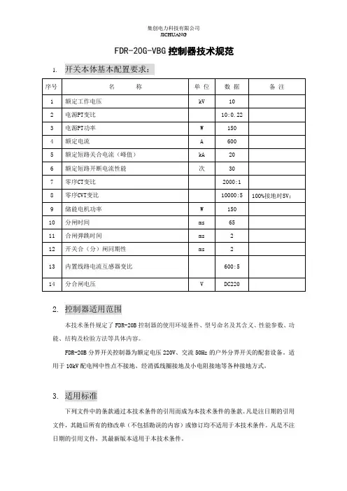
FDR-20G-VBG控制器技术规范1.开关本体基本配置要求:2.控制器适用范围本技术条件规定了FDR-20B控制器的使用环境条件、型号命名及其含义、性能参数、功能、结构及检验方法等具体内容。
F D R-20B分界开关控制器为额定电压220V、交流50H z的户外分界开关的配套设备。
适用于10k V配电网中性点不接地、经消弧线圈接地及小电阻接地等各种接地方式。
3.适用标准下列文件中的条款通过本技术条件的引用而成为本技术条件的条款。
凡是注日期的引用文件,其随后所有的修改单(不包括勘误的内容)或修订均不适用于本技术条件。
凡是不注日期的引用文件,其最新版本适用于本技术条件。
GB/T11022-1999---《高压开关设备控制和设备标准的共同技术条件》DL/T844-2003-----《12kV少维护户外配电开关设备通用技术条件-控制终端部分》GB/T7261-2000----《继电器及装置基本试验方法》GB/T11287-2000---《量度继电器和保护装置的振动试验(正弦) 》(idt IEC 60255-21-1:1988)GB/T14537-1993---《量度继电器和保护装置的冲击与碰撞试验》(idt IEC 60255-21-2:1988)GB/T17626.4-1998-《电磁兼容试验和测量技术电快速瞬变脉冲群抗扰度试验》(idtIEC 61000-4-4:1995)DL/T721-2000-----《配电网自动化系统远方终端》4.使用条件1) 海拔高度:≤1000米;2) 环境温度:户外 -40℃~+75℃;3) 相对湿度:最高年平均气温20℃,最高日平均气温30℃,≤90%(25℃);4) 最大日温差:25℃;5) 日照强度(风速O.5m/s时):0.1W/cm2;6) 最大风速:≤25m/s;7) 最大覆冰厚度:lOmm。
5.控制器性能参数6.绝缘电阻各电路分别与地(即外壳或外露的非带电金属零件)之间,交流电流电路与交流电压电路之间,交流电路与直流电路之间,用开路电压为500V的测试仪器测定其绝缘电阻值应不小于10M 。

使用说明书FZW28-12F(FFK)型户外交流分界负荷开关上海东自电气有限公司目录1.概述--------------------------------------------------------- 2 2.产品型号及含义 ---------------------------------------------- 4 3.使用条件 ---------------------------------------------------- 4 4.主要技术参数 ------------------------------------------------ 4 5.结构和工作原理 ---------------------------------------------- 6 6.安装与调试 -------------------------------------------------- 7 7.包装运输和储存 ---------------------------------------------- 12 8.使用和操作 -------------------------------------------------- 13 9.维护检查----------------------------------------------------- 14 10.订货条件----------------------------------------------------- 141、概述FZW28-12(F)户外高压交流分界真空负荷开关具备故障检测、保护、控制及通讯功能,安装于10kV线路上,可实现自动切除单相接地故障和自动隔离相间短路故障。
适用于三相交流50Hz、10kV的配电线路用户进线的T接或用户末端,也可用于符合要求的其它分支线连接处。
2、产品型号及含义额定短时耐受电流(kA)额定电流(A)分界用额定电压(kV)设计序号户外真空负荷开关3、使用条件3.1 正常使用条件:a)周围空气温度不超过 40℃,且在24h内测得的平均值不超过35℃;最低周围空气温度为-25℃;b)阳光辐射的影响可以忽略;c)海拔高度不超过1000m;d)周围空气可以受到尘埃、烟、腐蚀性气体、蒸气或盐雾的污染;污秽等级不得超过GB/T5582中的Ⅳ级;e)风速不超过34m/s(相应于圆柱表面上的700Pa);f)来自开关设备和控制设备外部的振动或地动是可以忽略的;g) 在二次系统中感应的电磁干扰的幅值不超过1.6kV。
Technical ArticleLeviton Mfg. Co., Inc. Lighting & Energy Solutions20497 SW Teton Avenue, Tualatin, OR 97062 1-800-736-6682 Tech Line: 1-800-959-6004 Fax: 503-404-5594 /les© 2012 Leviton Manufacturing Co., Inc. All rights reserved. Subject to change without notice.PL-PD-F007 Rev. 2 04/06/2009 LevNet RF™ Controlling a Fixture with Multiple SwitchesProduct: LevNet RF Wireless Solutions Article ID: 02102012-JE/TB-01Date: February 10, 2012Summary: This document describes how to control a light fixture from multiple locations using multipleswitches, both wired and wireless.Information:1. Use one relay receiver connected to the light and learn it to multiple wireless switches at the desired locations. A relay receiver can learn up to 30 different switches.2. Use a 5-wire relay connected to a 3-way wired switch:a. If only 1 wired switch is desired, it should be a 3-way switch. If more thanone wired switch is used then 4-way switches are needed. Wiring diagramsare available in the installation guide for the 5-Wire Relay Receiver.b. Teach receiver to respond to 1 or more wireless switches. Use Learn Mode3 to learn the top and bottom of the switch rocker in Toggle Mode. Thisresults in the relay switching state when either the top or bottom of theswitch is pressed which will replicating typical multi-way switchingfunctionality.c. When using the 5-wire relay in conjunction with a 3-way switch, themaximum load capacity is reduced to 3A because the N.C. (normallyclosed) contacts are used and have a lower current carrying capacity.Contact: If you have any questions or concerns, please call LES technical support at (800) 959-6004.。
FDR-330-M/Q面板型分界控制器(DC24V)安装使用说明书User’s Manual版本号:v 3.0尊敬的用户:为了您和设备的安全,在安装及使用本装置前,请认真阅读本说明书。
请妥善保存本说明书,以备查阅。
由于本产品技术不断更新,因此而引起的产品功能和性能的改变不包含在本说明书内,敬请谅解。
如果在安装及使用中遇到问题请与我司联系。
本说明书的解释权归我司,并保留一切权利。
安全信息本设备为交流220V 弱电设备,但在现场安装、维护时,附近有危险电压!本设备不能替代可见断开点,工作时应遵循所有当地批准的安全规程;否则,将因触高压导致严重人身伤亡。
本说明书并不能概括设备的安装、运行、维护等等的所有细节,如有问题请与我司联系。
接收、验货及存储每台FDR-330-M/Q 控制器在出厂前都经过了完整的装配、测试及检验,并进行了精心的校核、调整,运输前已经处于良好的状态。
接收时,仔细检查控制器在运输中有无损坏,如有问题,请立即向承运者提出书面报告。
包装件在装卸时小心轻放,避免碰伤和冲击,运输时应注意防水,严禁腐蚀性物品与包装件在同一车箱内运输。
如果本设备在安装前要存放相当长的时间,应放在清洁、通风良好的地方,空气中不得含有腐蚀性气体,存放时应小心,谨防损坏。
若控制器的后备电源为铅酸电池,其储存时间超过3 个月,应每过3 个月为电池充电一次,保证电池的使用寿命。
充电不少于24 小时。
目录1 概述 (4)1.1 应用 (4)1.2 特点 (4)2 技术性能指标 (5)2.1 使用环境条件 (5)2.2 电气技术参数 (5)2.3 主要技术指标 (6)2.4 电磁兼容 (7)2.5 绝缘耐压 (8)3 功能介绍 (8)3 主要功能 (8)3.1 遥控、遥测、遥信功能 (8)3.2 参数设置功能 (10)3.3 电源失电保护功能 (10)3.4 对时功能 (10)3.5 自诊断功能 (10)3.6 历史记录及上报功能 (11)3.7 故障检测 (11)3.8 通信功能 (12)3.9 当地调试功能 (12)3.10 高级故障处理功能 (12)4 参数说明 (14)4.1 盘面 (14)4.2 参数列表 (14)4.3 拨码盘整定值设置 (15)4.4 保护定值选择指南(以下所指电流为一次值) (16)5 附录 (17)5.1 线缆 (17)5.2 安装尺寸 (18)5.3 运输 (18)5.4 验收 (18)5.5 贮存 (18)6 检修:设备异常处理 (19)1.概述1.1应用FDR-330-MB 系列控制器是采用高速采样芯片和32 位高速单片机控制芯片相结合的新型高压开关控制器,能快速稳定的完成对高压开关的监控。

真空有载分接开关并联控制器使用说明书黑龙江省双城市机电技术开发有限公司一、概述本控制器采用美国MICROCHIP公司的单片机为主要器件组成的自动控制器,它与多台远程监控器、有载分接开关组成并联控制系统,其中也可任意几台独立运行,并具以下功能:1、所并联开关的档位不一致报警、保护功能2、超压、欠压、保护报警功能3、手动、自动功能4、RS—485接口,可实现计算机监控5、显示档位、电压二、技术参数三、工作原理并联控制器对电网电压取样,经CPU与予置的电压值进行比较,当取样电压超出予置电压范围时,经延时比较、判断,对已并联的开关输出相应的升、降信号,对开关进行升、降控制。
有载分接开关的并联选择由键1—6选择。
原理如图11、并联控制器与远程自动控制器的连结。
并联控制器后面板上有1#、2#、3#、4#、5#、6#六组D 型插坐,通过并联控制电缆,分别与1-6号有载分接开关远程自动控制器的COMC 口相连结。
示意图如下:2、并联控制器工作电源的连结并联控制器的工作电源是AC380V,同时又是并联控制器的电压取样电源,所以应取自并联运行变压器的低压侧,通过低压开关接至并联控制器。
3、COMA口是RS485通信接口,与计算机相联后,可实现计算机监控。
通信协议可向我厂索取。
4、1#—6#接线排列功能表:5、后面板端子功能1.端子1-6,内部为无源继电器常开点。
2.端子1-6,档位不同步时相对应的端子动作。
3.报警端子,开关不切换,开关报警时动作。
6、使用方法当所有电缆安装完毕检查无误后,开关与自动控制器、并联控制器分别接通工作电源后,按下面方法操作使用。
(1)电压上限、下限参数的予置和查看,●第一次按予置键:上限值闪烁,表示设定电压稳定范围的上限值,按升、降键修改,设定值范围390-430V。
●第二次按予置键:下限值闪烁,表示设定电压稳定范围的下限值,按升、降键修改,设定值范围360-390V。
第三次按予置键:升降延时闪烁,表示动作延时时间,按升降键修改,设定值范围20-60S。

Lumina™ RF 0-10V Dimming Wall SwitchCat. No. ZSD07-ADZDI-000-ZSD07-00ALEVITON LUMINA RF 0-10 V DIMMING WALL SWITCH OVERVIEWThe Lumina RF components are designed to communicate with each other via 2.4GHz Radio Frequency (RF) to provide remote control of your lighting. Each module in the Lumina RF component line is designed to act as part of a system. Line powered devices are designed to act as a router. These routers will re-transmit the RF signal from one device to another until the intended device is reached. This ensures that the signal is received by its intended device by routing the signal around obstacles and radio dead spots.CHANGING SWITCH COLORThe color of the Leviton Lumina RF 0-10 V Dimming Wall Switch may be changed to complement the interior décor. The Leviton Lumina RF 0-10 V Dimming Wall Switch is supplied with awhite, ivory and light almond switch plate. Additional colors are available; contact your Leviton ® distributor for more information. When changing the switch plate, before wiring and installation, proceed as follows:1. P ush in at two tabs on side to release (see Figure 2).2. L ine up and press in side to attach (see Figure 2).WIRINGThe Leviton Lumina RF 0-10V Dimming Wall Switch is wired directly to the load and utilizes a mechanical latching relay for power switching control from the Decora ® rocker. The device uses the 0-10V (Violet and Gray) wires to connect to the fixture for dimming. When multiple wall switches are controlling the same load, the following wiring instructions apply to each wall switch and the multi-location load control is completed through programming via the Leviton Lumina gateway. A gateway is required for all Lumina RF 0-10V Dimming Wall Switches to control programming. Please refer to the Lumina gateway user manual for details.NOTES:1. R efer to Figure 3 to determine the wire colors for each connection.2. W iring Connections:a. C onnect the Load (blue) wire to the lighting load.b. C onnect the Neutral (white) wire to the neutral supply.c. C onnect the Line (black) wire to single phase of the 120-277V supply.d. C onnect the Violet wire to the + 0-10V line and the Gray wire to the common 0-10V line.INSTALLATION 1. T O AVOID FIRE, SHOCK, OR DEATH; TURN OFF POWER at circuit breaker or fuse and test that power is off before wiring!2. I f applicable, remove the faceplate from the existing wall switch, remove the existing wall switch from the wall box, and disconnect the wires from the existing wall switch. Identify the "Line", "Neutral", "Load" and "Traveler" (if applicable) wires.NOTE: Existing traveler wire is not required for multi-location load control. If it exists, cap and tape wire so that it may be safely abandoned.3. R emove 3/4" of insulation from each of the wires on the Leviton Lumina RF 0-10V Dimming Wall Switch. Install the Leviton Lumina RF 0-10V Dimming Wall switch by connecting wires per wiring diagram (see Figure 3).4. A fter all connections have been made, ensure that all wire connectors are firmly attached and there is no exposed copper.5. G ently place the wires and the Leviton Lumina RF 0-10V Dimming Wall Switch into the wall box with the LED at the bottom of device. Using the supplied screws, attach the Leviton Lumina RF 0-10V Dimming Wall Switch to the wall box.6. B efore installing the faceplate, restore power to the circuit, and verify locator LED lights and switch ON/OFF operation.7. A fter testing the Leviton Lumina RF 0-10V Dimming Wall Switch and Multi-location Switches for proper local operation (see Figure 1), install a Decora faceplate over each switch.CLASS 2 INSTALLATION NOTE: This switch can be installed as Class 1 or Class 2. If installed as Class 2, all devices in the circuit must be Class 2 rated and this switch must be wired per instructions below, which are in accordance with NEC Code NFPA 70, paragraph 725.136 (d).For Class 2 Installation: The 0-10V control wires must be mechanically separated from Class 1, line, neutral and ground power lines. This can be accomplished by performing the following:1) I nstalling a mechanical barrier, in the form of silicone tubing or other non-conducting sleeve, over the length of 0-10V (Violet & Gray) control wires contained within the electrical box.1 32) U se of approved wire connectors shall be used to join the 0-10V control wires to building control wires. 2 33) W hen used with a 120V~ power source, if CL3, CL3R or CL3P rated control cables (or permitted substitute) is used to connect devices within the building, then siliconetubing or other non-conducting sleeve is not required over the control wires between wire connector and extending out of electrical box. However, a sleeve is still required over the control wires exiting the dimmer switch and extending into the wire connector. 1 2 31 S ilicone tubing shall be NRTL ( UL/CSA/ETL) recognized or equivalent to provide mechanical separation equal to .25” in air. .2 C onnectors joining 0-10V control wires shall be approved LISTED connectors.3 W ire connectors and wire tubing shall be provided by the installation contractor.NOTES:• 10A robust/commercial mechanical latching relay to handle high inrush (LED) and large loads.• U tilizes Leviton Lumina™ RF technology to communicate with other Lumina RF wireless compatible products.• R equires Lumina gateway for programming and control communication to other devices.WARNINGS AND CAUTIONS• T O AVOID FIRE, SHOCK, OR DEATH; TURN OFF POWER AT CIRCUIT BREAKER OR FUSE AND TEST THAT POWER IS OFF BEFORE WIRING!• T o be installed and/or used in accordance with appropriate electrical codes and regulations.• I f you are unsure about any part of these instructions, consult an electrician.WARNINGS AND CAUTIONS• U se this device with copper or copper clad wire only.• F or indoor applications only.• S ave these instructions.Figure 3 - Class 2 Wiring DiagramLumina™ RFFigure 1 - Lumina RF 0-10V Dimming Wall SwitchLOCATOR LEDPADDLE BOTTOM - tap to - tap to raisePADDLE TOP Figure 2 - Changing Switch ColorFOR CANADA ONLYFor warranty information and/or product returns, residents of Canada should contact Leviton in writing at Leviton Manufacturing of Canada Ltd to the attention of the Quality Assurance Department, 165 Hymus Blvd, Pointe-Claire (Quebec), Canada H9R 1E9 or by telephone at 1 800 405-5320.FCC COMPLIANCE STATEMENT:Contains FCC ID: W7Z-ZICM357SP0The enclosed device complies with Part 15 of the FCC Rules. Operation is subject to the following two conditions:(i.) This device may not cause harmful interference (ii.) This device must accept any interference received, including interference that may cause undesired operation. Any changes or modifications not expressly approved by Leviton could void the user’s authority to operate this equipment. This equipment has been tested and found to comply with the limits for a Class B digital device, pursuant to part 15 of the FCC Rules. These limits are designed to provide reasonable protection against harmful interference in a residential installation. This equipment generates uses and can radiate radio frequency energy and, if not installed and used in accordance with the instructions, may cause harmful interference to radio communications. However, there is no guarantee that interference will not occur in a particular installation. If this equipment does cause harmful interference to radio or television reception, which can be determined by turning the equipment off and on, the user is encouraged to try to correct the interference by one or more of the following measures:• Reorient or relocate the receiving antenna.• Increase the separation between the equipment and receiver.• Connect the equipment into an outlet on a circuit different from that to which the receiver is connected.• Consult the dealer or an experienced radio/TV technician for help.INDUSTRY CANADA COMPLIANCE STATEMENT:Contains IC: 8254A-ZICM357SP0.This device complies with Industry Canada license-exempt RSS standard(s). Operation is subject to the following two conditions: (1) this device may not cause interference, and (2) this device must accept any interference, including interference that may cause undesired operation of the device. IMPORTANT! Any changes or modifications not expressly approved by the party responsible for compliance could void the user’s authority to operate this equipment. This Class B digital apparatus complies with Canadian ICES-003.LEVITON LIMITED WARRANTYLeviton warrants to the original consumer purchaser and not for the benefit of anyone else that products manufactured by Leviton under the Leviton brand name (“Product”) will be free from defects in material and workmanship for the time periods indicated below, whichever is shorter: • OmniPro II and Lumina Pro : three (3) years from installation or 42 months from manufacture date. • Omni LTe, Omni IIe, and Lumina : two (2) years from installation or 30 months from manufacture date. • BitWise Controllers, Accessories : two (2) years from installation or 30 months from manufacture date. • Lumina Gateway Controllers : two (2) years from installation or 30 months from manufacture date. • Thermostats, Accessories : two (2) years from installation or 30 months from manufacture date. • Batteries : Rechargeable batteries in products are warranted for ninety (90) days from date of purchase. Note : Primary (non-rechargeable) batteries shipped in products are not warranted. Products with Windows ® Operating Systems : During the warranty period, Leviton will restore corrupted operating systems to factory default at no charge, provided that the product has been used as originally intended. Installation of non-Leviton software or modification of the operating system voids this warranty. Leviton’s obligation under this Limited Warranty is limited to the repair or replacement, at Leviton’s option, of Product that fails due to defect in material or workmanship. Leviton reserves the right to replace product under this Limited Warranty with new or remanufactured product. Leviton will not be responsible for labor costs of removal or reinstallation of Product . The repaired or replaced product is then warranted under the terms of this Limited Warranty for the remainder of the Limited Warranty time period or ninety (90) days, whichever is longer. This Limited Warranty does not cover PC-based software products. Leviton is not responsible for conditions or applications beyond Leviton’s control. Leviton is not responsible for issues related to improper installation, including failure to follow written Installation and operation instructions, normal wear and tear, catastrophe, fault or negligence of the user or other problems external to the Product . To view complete warranty and instructions for returning product, please visit us at .SETUP MODE FOR CONTROLS COMMUNICATIONConfigure the Leviton Lumina RF 0-10V Dimming Wall Switch using a Lumina gateway. Visit the Leviton Cloud Service at for gateway installation software. NOTE: The device must be in mode 1, enrollment while the Lumina gateway is searching for new devices to Enroll.NOTE: The pairing mode happens very quickly once it scans network and finds another device in identify mode. Devices need to be enrolled in network for 3-way pairing to work. Pairing and Identify needs to be done on both devices for full 3-way control. The maximum amount of devices that can be paired is 8 devices.SWITCH OPERATIONLocal Rocker Switch OperationThe Leviton Lumina RF 0-10V Dimming Wall Switch has a rocker that can be used to control the load (see Figure 1).LED IndicatorThe Leviton Lumina RF 0-10V Dimming Wall Switch comes equipped with a locator LED indicator that is normally lit to green when the load is OFF. The locator LED is OFF when the load is ON.Dimming LED IndicatorThe Leviton Lumina RF 0-10V Dimming Wall Switch also has a dimming indicator on the left side of the switch to display the current dimming level via single bright LED - the remaining LED’s will be lit at a dimmer level to display range of dimming. The bright LED will move up or down the dimming indicator based on user presses to the Dim/Bright rocker.。


使用说明书FZW28-12F(FFK)型户外交流分界负荷开关上海东自电气有限公司目录1.概述--------------------------------------------------------- 2 2.产品型号及含义 ---------------------------------------------- 4 3.使用条件 ---------------------------------------------------- 4 4.主要技术参数 ------------------------------------------------ 4 5.结构和工作原理 ---------------------------------------------- 6 6.安装与调试 -------------------------------------------------- 7 7.包装运输和储存 ---------------------------------------------- 12 8.使用和操作 -------------------------------------------------- 13 9.维护检查----------------------------------------------------- 14 10.订货条件----------------------------------------------------- 141、概述FZW28-12(F)户外高压交流分界真空负荷开关具备故障检测、保护、控制及通讯功能,安装于10kV线路上,可实现自动切除单相接地故障和自动隔离相间短路故障。
适用于三相交流50Hz、10kV的配电线路用户进线的T接或用户末端,也可用于符合要求的其它分支线连接处。
2、产品型号及含义额定短时耐受电流(kA)额定电流(A)分界用额定电压(kV)设计序号户外真空负荷开关3、使用条件3.1 正常使用条件:a)周围空气温度不超过 40℃,且在24h内测得的平均值不超过35℃;最低周围空气温度为-25℃;b)阳光辐射的影响可以忽略;c)海拔高度不超过1000m;d)周围空气可以受到尘埃、烟、腐蚀性气体、蒸气或盐雾的污染;污秽等级不得超过GB/T5582中的Ⅳ级;e)风速不超过34m/s(相应于圆柱表面上的700Pa);f)来自开关设备和控制设备外部的振动或地动是可以忽略的;g) 在二次系统中感应的电磁干扰的幅值不超过1.6kV。
中科电力装备集团有限公司JN15型户内高压接地开关安装使用说明书微软用户[选取日期]安全第一!接地开关只能安装于适合电气设备工作的户内场所;必须保证现场电气设备安装条件的适用性与安全性;确保由专业人员来进行安装、操作和维护;有关接地开关的一切操作,都应遵守本说明书的相应规定;使用中不要超过接地开关正常工作条件下技术参数的规定值;说明书应放置在与安装、操作及维护有关的人员方便拿到的地方;用户的专职人员应对所有影响安全的事项负责,并正确使用接地开关;若对本使用说明书尚有疑问,我们很乐意为您提供进一步咨询。
目录1、概述 (4)2、型号的表达方式 (4)3、产品依据标准 (4)4、使用环境条件 (4)5、接地开关主要技术参数 (4)6、产品结构及工作原理 (5)7、外形及安装尺寸图 (5)8、接地开关内部电气原理图 (10)9、运输储存 (10)10、中期储存 (11)11、安装 (11)12、调试与操作 (12)13、维修 (13)14、产品随机提供以下文件 (14)15、产品订货须知 (14)1、概述JN15系列户内交流高压接地(以下简称接地开关)是三相交流50Hz、额定电压为12~40.5kV 的户内高压开关设备。
在电力系统中与多种型号高压开关柜配套使用,亦可作为高压电器设备检修时接地用。
2、型号的表达方式3、产品依据标准ZN63(VS1)-12系列接地开关设计和制造符合GB1985 《高压交流隔离开关和接地开关》、GB/T11022 《高压开关设备和控制设备的共用技术要求》、IEC60129 《高压交流隔离开关和接地开关》等标准的相关要求。
4、使用环境条件4.1正常使用条件a)环境温度最高温度:+40℃;最低温度:-15℃;日平均温度值不超过+35℃。
b)环境湿度相对湿度:日平均值≤95%,月平均值≤90%;水蒸气压:日平均值≤ 2.2KPa,月平均值≤1.8KPa。
c)设备安装场所海拔高度不超过1000米。
灾报警控制器FS-3030/E作维修手册火灾报警系统的局限火灾报警系统可以降低保险费用,但并不能代替火灾保险!自动火灾报警系统——典型组成包括感烟探测器、感温探测器、手动报警按钮、音响警报装置和具有远程告警能力的火灾报警控制——可以对发生的火灾提供早期警报。
然而,这种系统并不能保证由于火灾造成的财产损失和人员伤亡。
制造商推荐感烟和感温探测器在保护场所的设置应遵循“国家火灾防护协会通用版72号标准”(NFPA72)的建议、制造商的建议、国家和地方法规以及《正确使用系统感烟探测器指南》中的建议。
该指南对所有安装经销商免费提供。
据联邦紧急事件处理机构(美国政府机构)研究指出,感烟探测器在多达35%的火灾中没有起作用。
当火灾报警系统为早期火灾提供报警时,它们不保证对火灾的报警和防护。
由于以下各种原因,火灾报警系统可能不能提供及时准确的警报,甚至不能动作:感烟探测器在烟到达不了探测器的地方将不能探测到火灾,例如在烟囱里,在墙的里面或后面,在屋顶,或在关闭门的另一侧。
在建筑物的另一级或另一层的感烟探测器也不能探测到火灾,例如,第二层的探测器不能探测到的一层或地下室的火灾。
燃烧的粒子或“烟”在发展中的火灾中的燃烧粒子或“烟”将有可能不能到达感烟探测器的探测室,这是由于:像关闭或部分关闭的门、墙或烟囱等障碍物阻挡了粒子或烟的流动。
烟粒子变“冷”凝结不能扩散到安装探测器的屋顶或墙上面。
烟粒子被空气出口吹离探测器。
烟雾在到达探测器前被拉回到空气中。
“烟”的数量不足以使感烟探测器报警。
感烟探测器被设计为依据烟的浓度不同等级报警。
如果在探测器的位置发生火灾产生的烟达不到该浓度等级,探测器将不报警。
感烟探测器,即使工作正常,也有探测限制。
具有光电探测室的探测器善于探测阴燃的火灾而不善于探测很少有可见烟的明火。
具有离子型探测室的探测器善于探测快速燃烧的火灾而不善于探测阴燃火灾。
由于火灾以不同方式发展,而且它们的蔓延经常不可预知,两种探测器都不能最好地配置,一种给定点探测器将不能提供适当的火灾报警。
JN-K(R)系列控制器使用说明书首先感谢您购买使用我司的JN-K(R)系列机器,为了您能更好的了解和使用我们的产品。
请在安装及使用本产品前务必仔细阅读使用说明书,并妥善保管。
本产品的安装、调试接线均需按照本手册指导来进行。
误用或错误的连接机器可能会造成人身伤害或者损坏机器及其用电设备。
1.0注意事项■使用之前请仔细阅读手册中的所有说明和注意事项。
■用户不要自行拆卸和维修控制器。
■室外安装时应避免阳光直晒。
■建议在控制器外部安装合适的保险丝或断路器。
■在安装和调整控制器的接线前务必断开光伏阵列及蓄电池回路。
■安装蓄电池时要非常小心,对于开口式铅酸蓄电池的安装应戴上防护镜一旦接触到蓄电池酸液时,请及时用清水冲洗。
■蓄电池附近避免放置金属物件,防止蓄电池发生短路。
■蓄电池充电时可能产生酸性气体,确保环境周围通风良好。
■虚接的连接点和腐蚀的电线可能造成极大的发热融化电线绝缘层,燃烧周围的材料,甚至引起火灾;所以要保证连接头都拧紧,电线最好用扎带都固定好,避免移动应用时电线摇晃而造成连接头松散。
■控制器上的蓄电池接线端子既可以同一只蓄电池连接,也可以同一组蓄电池连接。
手册里后续说明都是针对单只蓄电池使用时,但是同样适用于一组蓄电池的系统。
■系统连接线按照不大于4A/㎜²的电流密度进行选取。
2.0产品简介本系列控制器采用最先进的数控技术设计,液晶屏显示,全自动运行。
采用脉宽调制(PWM)式的蓄电池充电方式及独特的控制技术将大大提高蓄电池的寿命。
本产品拥有很多独特的功能,使用非常方便。
2.1产品概述本控制器适用于太阳能离网系统(独立系统)中,自动控制充电和放电过程。
控制器的蓄电池充放电过程是经过优化的,能够延长蓄电池寿命,改善系统性能。
其全面的自测功能和电子保护功能可以避免由于安装错误和系统故障而导致的控制器损坏。
◆使用高速性能优越的CPU处理器◆高精度A/D采样保证采样的准确性◆优良的EMC设计◆智能温控降电流◆12V/24V系统电压自动识别或48V蓄电池工作电压◆高效的串联式PWM充电方式,延长了蓄电池寿命,提高了系统性能◆采用全进口功率MOSFET作为电子开关,损耗小,可靠性高◆具有广泛的适用性,自动识别白天/黑夜◆采用液晶显示及按键人机界面,完整的菜单式显示及操作◆人性化设计的浏览界面,方便各项操作◆完整的现场控制参数的设定及修改◆多样的负载控制方式与智能记忆功能,增强了负载输出的灵活性◆采用温度补偿充电控制算法,系统自动调整充放电参数,提高蓄电池使用寿命◆控制器光电池输入滤波功能,有效去除光电池电压尖峰给设备带来的危害◆使用基于RS-232通讯总线,通讯速度快,通讯协议兼容性好。
分界开关智能控制器TH700-FDR(V2.0)前言亲爱的用户,感谢您们长期以来的大力支持,我们秉承给予您们热诚、周到、满意、快捷永远的服务。
请在使用该设备之前仔细阅读本技术使用手册,特别注意以下事项。
注意事项! 装置加电之前必须可靠接地。
! 装置工作电源位置是否接正确,电流输入极性是否接正确,电压输入相序是否接正确。
! 严禁装置在带电情况下插拔航空插头,避免一次回路CT开路。
! 装置交流回路1.2倍额定电压可以连续工作,交流回路2倍额定电流可以连续工作,10倍额定电流可允许10S,40倍额定电流可允许1S。
! 装置开入量的输入为无源接点(装置内提供DC220V直流电压),请仔细检查是否正确。
! 储能电机电源为AC220V交流电压,从本装置内输出。
! 第一次运行该产品时,必须进行相关定值整定才能保障装置正常运行,非相关专业人员不得修改装置内参数、定值等内容。
! 相关专业人员严格按电力调度或生产部门下达的定值单进行定值整定以及系统配置的设定,只有正确进行全面整定后才能确保装置安全可靠运行。
谢谢合作!!1.产品纵述本公司长期以来从事电力系统自动化系统及设备研究、开发、生产,属高科技企业,现已推出TH700-FDR智能控制器。
TH700-FDR“看门狗”控制器是中压架空线电网的监控单元,与柱上开关配合实现远程遥控及自动化管理,监控单元适合与开关近距离安装,适用于35KV及以下户外开关设备配套使用。
TH700-FDR“看门狗”控制器是集线路测量、保护、控制、信号监视及通讯于一体的综合自动化户外智能控制设备,适用于各种中压电网(不接地电网、经电阻接地、经消弧线圈接地、直接接地电网),具备处理单条架空线开关远程操作的全部功能。
具备基本的保护功能:线路保护功能、自动重合闸、线路故障检测、接地故障监测、开关的本地控制、远程遥控功能(带手持遥控器)、GPRS远程操作(选配)。
2.产品的安装及维护注意:在安装装置过程中,装置带有危险的强电有可能会导致设备永久性损坏或人员伤亡,因此在安装、调试、检修操作时仅限于经过严格的培训和具有该专业技术人员。
J N F D R分界开关控制器说明书BDocument serial number【LGGKGB-LGG98YT-LGGT8CB-LGUT-2000系列保护装置JN-FDR2000分界开关控制器工程应用指南Engineering guide河北杰能电气设备有限公司Version目录概述10kV架空配电线路T 接的用户内部发生故障时,如故障在其进线段,或故障虽发生在用户进线开关内侧但其保护动作时限与变电站出线开关保护配合不当时,均会造成变电站出线开关保护掉闸。
如果故障性质是永久的,变电站重合不成功,则一个中压用户界内的事故将使整条配电线路停电,这种在配电网中常见的波及事故,对社会将造成恶劣影响。
用户分界负荷开关是解决上述波及事故的理想设备,该设备安装于10kV架空配电线路的责任分界点处,可以实现自动切除单相接地故障和自动隔离相间短路故障。
确保非故障用户的用电安全。
用户分界负荷开关控制器是专门用于分界开关本体的智能控制。
实现保护控制功能和通信功能,控制器与开关本体通过控制电缆和航空接插件进行电气连接,实现其保护及自动监控功能。
该产品广泛适用于城乡10kV架空配电线路用户。
应用示意图如下:故障分界开关应用示意图技术参数使用环境条件a) 环境温度:户外 -40℃~+80℃b) 抗震能力:地面水平加速度、地面垂直加速度同时作用持续三个正弦波,安全系数c) 最大日温差: 25℃d) 日照强度: cm2(风速s时)e) 最大风速:≤25m/sf) 最大覆冰厚度: 10mmg) 运行环境:户外、无易燃、爆炸危险、化学腐蚀及剧烈振动的场所特点功能控制器的特点➢可以快速切除界内故障,速断动作时间小于30毫秒。
➢控制器为32位微机型的继电保护及监控装置,预留以太网通讯接口,满足电力系统信息化的要求;➢模拟量可以采集四个电流和四个电压,支持六种接线方式,可以适应多种功能要求。
比如遥测计算有功功率(P)、无功功率(Q)、功率因数。
➢既可以采取GPRS方式也可以短信方式,短信方式发中文短信和字符短信,比单纯发字符短信的产品使用起来更加直观。
➢有专门的控制字设定保护动作后是立即跳闸还是等失压后跳闸,所以既可以与断路器配合也可以与负荷开关配合。
➢与预付费电能表配合,实现预付费控制功能。
还可以扩展,在未经授权的情况下,打开计量箱门,强制断电的功能,起到防窃电的功能。
➢接地保护可以选择带方向或不带方向。
➢短信可以设置发或不发,使测试更加方便。
➢开关量信号可以软件取反。
保护功能及工作原理10KV馈线或设备的故障主要有相间短路和单相接地两种类型,控制器对这两种故障分别进行处理。
1 相间短路故障的处理对于用户界内的相间短路故障,控制器通过检测从分界开关内部采集的A C相电流与定值比较来判断故障的发生,当大于定值,立即跳闸把故障隔离掉,不影响非故障区域的供电。
即便由于定值的选择性问题,某些故障造成了变电站出线开关的也跳闸了,但变电站重合后,故障点已经被隔离,非故障区域可以很快恢复供电。
设三段定时限过流保护(过流Ⅰ段、过流Ⅱ段和过负荷),各段电流及时间定值可独立整定,分别设置整定控制字控制这三段保护的投退。
过负荷可以选择跳闸或告警。
特点功能专门设置一段加速段电流保护,在手合或重合闸后投入3秒,而不是选择加速Ⅰ段、Ⅱ段。
可以由控制字投退,加速段的电流及时间可独立整定。
2 单相接地故障的处理控制器通过检测从分界开关内采集的零序电流与定值的比较来区分和判断用户界内和界外的单相接地故障,对于用户界外的单相接地故障,由于零序电流远小于用户界内发生单相接地故障时的零序电流,因此,通过设定适当的定值,即可做出准确的判断。
接地保护可以选择带方向或不带方向。
有零序电压时可以选择带方向。
可以选择跳闸或告警。
3 重合闸有最大四次重合闸,每次的投退可单独控制,每次的延时可独立整定。
可以投退合闸后加速功能。
GPRS或短信方式的通信功能可以通过手机网络,采样GPRS方式或短信方式与监控系统通信,实现远程的采集和控制。
比如采集电流、开关状态等,远程遥控跳闸、合闸。
采用GPRS方式还是短信方式订货时可以选择。
采用短信方式时,可以发中文和字符两种格式的短信,两种格式自动切换。
也可以选择使用专用通道,比如光纤通道。
遥控、遥测、遥信功能遥控功能有:遥控跳闸操作,遥控合闸操作。
遥测量主要有:IA IB IC I0 UAB UCB U0 UP COSφ、P、Q,精度达到级。
UP是电源电源。
遥信量主要有:6路遥信开入、装置变位遥信及事故遥信,并作事件顺序记录,遥信分辨率小于2ms。
对时功能可以通过调度通过通信对时,也可以使用手机通过短信对时,也可以使用专用测试软件对时。
特点功能PT监测功能PT是一个相对容易出故障的元件,因此,本装置特设PT的实时监测功能。
有电流,电压没有或低于门槛(额定电压的60%)判断为PT异常,立即发送事项短信通知。
备用电源功能使用大容量的电容做备用电源,长寿命、免维护,避免了电池寿命短的缺点。
实时监视电源电压,一旦失压将发出交流失电短信。
交流失电后10秒内可以进行一次跳闸、合闸操作。
当然,也可以选择使用电池做备用电源,订货时说明即可。
事项记录保存功能可以存储32条事件顺序记录(SOE记录),和16条保护动作记录。
掉电不消失。
方便事故的追忆和分析。
自动发送事项短信功能实时监视现场状态的变化,一旦发生变化立即向指定的手机号码(可以是多个手机号)发送发送事件报告,事件报告是中文的,很直观。
该功能可以通过控制字关闭或打开。
可以发送的事件报告包括(比如安装在开关厂):特点功能专用测试软件提供基于WINDOWS系统的,配套的专门测试软件,现场的设置和查询非常方便,比如设地址编号、定值、参数、安装地点等。
现场遥控器遥控使用配套的无线遥控器可以就地跳闸、合闸、复归。
遥控器有四个键,A B C D。
跳闸操作:按“D”,3秒内按“A”键。
合闸操作:按“D”键,3秒内按“B”键;复归操作:按“D”键,3秒内按“C”键。
遥控检查通过短信的远程遥控和使用遥控器的就地遥控,装置都能自动检查遥控操作的合理性。
比如开关分位再跳闸或开关合位再合闸,未储能合闸都认为是不允许的操作。
对于检查出的不允许的操作,远程遥控会响应相应的提示信息,就地遥控器遥控,则操作自动被取消。
多种定值整定方式特点功能为了适应不同的使用习惯,本装置的定值可以通过拨码轮整定,也可以通过通信整定,通过拨码轮整定的叫拨码轮定值,通过通信整定的叫通信定值,装置管理着两套定值,可以选择使用那一套定值,两套定值都可以在调度查看,也都可以使用手机查看。
硬件闭锁超级号码的整定手机网络是一个开放的网络,超级号码有所有的权限,尤其是控制和定值、参数整定的权限,所以,超级号码的安全是至关重要的。
因此,本装置特设一个硬件的闭锁开关,只有把本开关置于调试状态,才能修改超级号码,在运行状态是不可能被修改的。
而且,闭锁开关的状态可以在调度实时监视。
开入取反功能可以通过参数设置让软件对接入的开关量取反,这样就既可以接常开也可以接常闭,使用比较方便。
使用说明控制器底盖面板各部件的名称如下图所示:运行指示灯运行指示灯是双色、高亮度指示灯,一个是兰色一个是黄色。
安装到杆上后,可以就地观察装置的运行情况。
下表列出了这两个灯的含义:使用说明-黄灯亮时可以通过四种方式复归:通过面板上的操作手柄复归,使用遥控器复归,使用掌上电脑通过无线模块或通信线遥控复归,用GPRS 或短信复归。
控制操作手柄向右拨用于就地复归操作;向左拨是当地位置,用于检修设备时,闭锁合闸,此时通过控制器是合不了闸的。
就地复归信号,当地状态信号都能被自动检测,并生产带时间标签的事项记录。
图中各元件的说明如下表:使用说明注意:1)上表中所有电流定值均为二次电流值。
2)选择拨码轮定值有效需要把参数中的“定值选择”项设为0,否则有效定值会选择通信设的定值。
出厂时该参数是0,即默认是选择拨码轮定值为有效定值。
需要使用通信设的定值时,把该参数改为1即可。
超级用户和一般用户的设置一台设备就一个超级用户。
在调试态下才允许设置超级用户,只有超级用户才能设置其他用户,遥控也只有超级用户才行。
不设超级用户,就设不了一般用户。
在已经成功登录到GSM网络后进行,现象是三个网络质量灯至少有一个是亮的。
1)、把“运行/调试”开关拨到调试状态。
2)、手机发字符短信:SZHMCJ:678。
3)、收到短信:OK。
4)、把“运行/调试”开关拨到运行状态。
很重要,一定要置于运行状态,只有在调试需要时临时切换到调试状态,之后恢复运行状态。
1)、一定要用超级用户号码的手机发短信。
2)、短信内容:SZHMYB:4,,,,。
3)、收到短信:OK。
设安装地点本装置发的事项短信包含安装地点信息,要比单纯的从电话号码索引从哪个地方发来的直观的多,所以要设置安装地点。
只有超级用户可以。
设置的方法如下:比如安装地点是“521线路6号杆”,该地点的SIM卡号是139********,则给该号码发短信,其内容是“设02,01,08,521线路6号杆,OK”,其中“08”是汉字的个数,“521线路6号杆”是安装地点。
短信内容中汉字个数、安装地点可以改变,别的不能改变。
该短信既可以通过手机发,也可以在主站通过我们配套提供的专业软件发。
使用说明设好安装地点后,比如09年1月3号11点02分33秒,该开关跳闸。
则收到的事项短信是“09年1月3号11点02分33秒521线路6号杆跳闸”设地址编号在使用专用通道通信时,比如光纤通道,每个设备要有一个唯一的地址编号,所以需要设置。
要使用配套的专用测试软件设置。
使用专用测试软件的方法如下:S2选择到调试状态,读参数,参数中改成需要设的地址,设置参数,S2选择到运行状态。
使用GPRS或GSM时不需要设置地址。
设备出厂默认地址都是1。
手持遥控器使用遥控器外形如右图:A:分闸按钮 B:合闸按钮 D:解锁按钮 C:复归按钮遥控操作:跳闸操作:按“D”键,3秒内按“A”键合闸操作:按“D”键,3秒内按“B”键复归操作:按“D”键,3秒内按“C”键安装连接柱上安装示意图分界开关本体与控制器同杆安装,其连接如下图:安装连接控制器的安装及尺寸安装示意图(单位:mm)安装连接航空端子的定义安装连接附录A短信数据格式中文短信设置安装地点只有超级用户可以。
比如安装地点是“521线路6号杆”,短信内容是“设02,01,08,521线路6号杆,OK”,其中08是汉字的个数。
短信内容中汉字个数、汉字内容可以改变,别的不能改变,其中标点符号是全角符号。
主动发送的事项短信举例,比如09年1月3号11点02分33秒,开关跳闸。
装置发的中文短信是“09年1月3号11点02分33秒521线路6号杆跳闸”主动发送的中文短信事项有以下这些:1)、杆下遥控跳闸,2)杆下遥控合闸,3)就地复归,4)一次重合闸,5)二次重合闸,6)三次重合闸,7)四次重合闸,8)PT失压,9)强制跳闸,10)合闸,11)跳闸,12)过流I段跳闸,13)过流II段跳闸,14)过流加速段跳闸,15)过负荷跳闸,16)过负荷告警,17)接地跳闸,18)接地告警。