Pantum P2500系列维修手册
- 格式:pdf
- 大小:6.53 MB
- 文档页数:98

东芝服务便携手册——凤e-STUDIO2505/2505H/2505FV4.1中国事业总部服务支持统括部东芝泰格信息系统(深圳)有限公司2014-04目录一、基本清单 (2)(一)基本规格清单 (2)(二)耗材清单 (2)(三)常用电路板及零件清单 (3)(四)选购件清单 (4)(五)PM零件清单 (4)二、错误代码及故障排错参考 (5)(一)卡纸类错误代码 (5)(二)维修请求错误代码 (7)(三)E-MAIL相关错误代码 (10)(四)文件共享相关错误代码 (10)(五)其他错误 (10)三、维修模式列表 (11)四、辅助维修模式(3C) (12)五、SRAM清除模式(6C) (12)六、列表打印模式(9S) (13)七、PM支持模式(6S) (14)(一)操作流程 (14)(二)菜单列表 (14)(三)基本操作过程 (15)八、输入测试模式(03) (16)九、输出测试模式(03) (17)十、打印测试模式(04) (17)十一、05/08代码 (18)(一)常用05调整代码 (18)(二)05模式打印测试图 (21)(三)常用08设置代码 (21)(四)图像尺寸相关调整代码表 (30)(五)图像质量调整代码表(复印相关) (30)(六)图像质量调整代码表(打印相关) (31)(七)图像质量调整代码表(扫描相关)(仅2505H/F) (31)(八)ADF相关调整 (31)十二、传真错误代码及排错参考(仅2505F) (32)(一)传真卡电路相关错误代码(仅2505F) (32)(二)传真发送相关错误代码(仅2505F) (32)(三)传真接收相关错误代码(仅2505F) (34)十三、传真相关的自诊断模式(仅2505F) (36)(一)03测试模式(仅2505F) (36)(二)08设置模式(仅2505F) (36)(三)13传真功能模式(仅2505F) (36)(四)1*传真清除模式(仅2505F) (37)十四、F/W升级 (38)(一)使用USB进行F/W (38)(二)使用PC升级工具进行F/W升级 (39)十五、电路板更换 (40)(一)主板更换步骤 (40)(二)主板的EEPROM更换步骤 (40)附录 (41)(一)电器元件布局图 (41)(二)电器元件符号及功能表 (43)(三)纸路布局图 (44)(四)驱动电器布局图 (44)(五)ADF布局图 (45)(六)交流线束图 (45)(七)直流线束图(2505) (46)(八)直流线束图(2505H/F) (47)一、基本清单(一)基本规格清单注意:随机包装的墨粉容量为2K。
INSTALLATION AND SERVICEMANUAL FORLANCER SERIES 2500DISPENSERSFAX ENGINEERING:•210-310-7096"Lancer" is the registered trademark of Lancer •Copyright — 2004 by Lancer, all rights reserved.Please refer to the Lancer web site ( ) for information relating to Lancer Installation and Service Manuals,Instruction Sheets, Technical Bulletins, Service Bulletins, etc.6655 LANCER BLVD. • SAN ANTONIO, TEXAS 78219 USA • (210) 310-7000FAX SALES• NORTH AMERICA – 210-310-7245 • INTERNATIONAL SALES – 210-310-7242 • CUSTOMER SERVICE – 210-310-7242 •• LATIN AMERICA – 210-310-7245 • EUROPE – 32-2-755-2399 • PACIFIC – 61-8-8268-1978 •iNOTES NOTESiii1.INSTALLATION1.1RECEIVINGEach unit is completely tested under operating conditions and thoroughly inspected before shipment. At time of shipment, the carrier accepts the unit and any claim for damages must be madewith the carrier. Upon receiving units from the delivering carrier, carefully inspect carton for visibleindication of damage. If damage exists, have carrier note same on bill of lading and file a claim withthe carrier.1.2UNPACKINGA.Cut band and remove.B.Remove top portion of carton by lifting up.C.Remove top inner carton pad and corners.D.Lift Unit up by plywood shipping base and remove lower portion of carton.E.Inspect unit for concealed damage and if evident, notify delivering carrier and file a claim againstsame.F.Remove plywood shipping base from unit by moving unit so that one side is off the counter topor table, allowing access to screws on the bottom of the plywood shipping base.G.If Unit is to be installed with optional legs, assemble legs to unit by tilting unit. DO NOT LAYUNIT ON ITS SIDE OR BACK.H.Remove accessory kit of loose parts from drip tray.1.3SELECTING A COUNTER LOCATIONThe dispenser is designed to sit on a flat, supported surface capable of supporting a minimumweight of 400 pounds (182 kg). It may be either counter or leg mounted. A template is furnished tocut and/or drill the necessary holes for mounting. When the dispenser is to be permanently boltedto the counter top, seal dispenser base to counter top with a silicone sealant which provides asmooth and easily cleanable bond to the counter.Locate dispenser to allow approximately 15 inches (380 mm) of unobstructed space above and six (6) inches (160 mm) behind the unit for proper air circulation. Air is drawn in through the backgrill and exhausted out of the top grill.1.4CONNECTING THE DRAINA.Remove cup rest. Lift splash plate up and pull out and down on the bottom to remove.B.Remove the drip tray from the unit and connect the drain tube to the drain fitting located on thebottom. Secure drain tube with clamp provided in accessory kit.C.Route the drain tube to a suitable drain and replace the unit's drip tray.1.5FILLING UNIT WITH WATERA.Remove the bonnet from the unit.B.Remove the yellow plastic plug from the fill hole.ing a funnel or tube, fill the water bath compartment with water until it flows out of theoverflow tube into the drip tray. Use bottled water where a water problem exists.D.Replace the yellow plug.11.6CONNECTING TO ELECTRICAL POWERA.Check the dispenser serial number plate for unit's correct electrical requirements. Do not pluginto electrical outlet unless unit electrical configuration, located on serial plate, agrees with localavailable power supply.B.Route the power supply cord to a grounded electrical outlet of the proper voltage andamperage rating, and plug in the unit. This will turn on the refrigeration system and allow it tostart cooling while completing the rest of the installation. Approximately three (3) hours arerequired to form a full ice bank.1.7CONNECTING TO PLAIN WATER SUPPLYSee Figure 1.If unit has no plain water circuits, proceed to Section 1.8.A.Valves 4, 5, and 6 through 8 (on 8 valve units) and valves 3, 4, and 5 (on 6 valve units) haveoptional plain water or carbonated water capabilities. Using Figure 1, determine which valvesare to be plumbed with plain water.ing proper beverage tubing and fittings, connect to water source [must be 35 PSI (2.4 bar) ormore].C.Flush water supply line thoroughly.D.Route tubing through cutout in counter or through access hole in back of unit.E.Leave 12 inches (300 mm) of extra tubing length below the counter for servicing and movingthe dispenser.F.Connect to desired plain water inlet behind splash plate and secure with Oetiker Clamp.G.Turn on water supply and check for leaks.H.Actuate each valve until all air is expelled.Plumbing Diagram, Carbonated/Plain WaterFigure 1232.SCHEDULED MAINTENANCE2.1DAILYA.Remove the nozzle and diffuser from each valve and rinse well in warm water. Do NOT usesoap or detergent. This will cause foaming and off taste in finished product.B.Remove the cup rest and wash in warm soapy water.C.Pour warm soapy water into the drip tray and wipe with a clean cloth.D.With a clean cloth and warm water, wipe off all of the unit's exterior surfaces. DO NOT USEABRASIVE SOAPS OR STRONG DETERGENTS.E.Replace the cup rest, valve diffusers, and valve nozzles.2.2WEEKLYA.Taste each product for off tastes and/or brix changes.B.Remove the bonnet and check the level of water in the water bath. Replenish as required, andreplace the bonnet.2.3MONTHLYA.Unplug the dispenser from power source.B.Remove the bonnet and clean the dirt from the condenser using a soft brush.C.Replace the bonnet and plug in the unit.2.4EVERY SIX MONTHSA.Clean and sanitize the unit using the appropriate procedures outlined in Section 3 of thismanual.2.5YEARLYA Clean water bath interior, including evaporator coils and refrigeration components.B.Clean the entire exterior of the unit.C.Sanitize syrup lines.3.DISPENSER CLEANING AND SANITIZING3.1AMBIENT PROCESSA.The ambient process is the most common method for cleaning and sanitizing dispenserequipment. The detergent should be caustic-based and the sanitizer should be low pH (7.0)chloride solution.B.Disconnect syrup containers and remove product from tubing by purging with carbon dioxide.C.Rinse the lines and fittings with clean, room temperature water to remove all traces of residualproduct.D.Fill lines with a caustic-based (low-sudsing, non-perfumed, and easily rinsed) detergent solu-tion. The solution should be prepared in accordance with the manufacturer’s recommendations,but should be at least two (2) percent sodium hydroxide. Make sure the lines are completelyfilled and allow to stand for at least ten (10) minutes.E.Flush the detergent solution from the lines with clean water. Continue rinsing until testing withphenolpthalein shows that the rinse water is free of residual detergent.F.Fill the lines with a low pH (7.0) chlorine solution containing at least 50 parts per million (PPM)(50 mg/L) available chlorine. Make sure that lines are completely filled and allow to stand forten (10) minutes.G.Reconnect syrup containers and ready Unit for operation.H.Draw drinks to refill lines and flush the chlorine solution from the dispenser.I.Taste the beverage to verify that there is no off taste.3.2VALVESA.Valves may be cleaned and sanitized in the same manner1.Remove cover and disconnect power so not to activate the valve while cleaning. Removenozzle and diffuser. Wash these parts in cleaning solution, then immerse them in a bath ofsanitizing solution for 15 minutes.42.Visually inspect around nozzle area for syrup residue. This area may be cleaned with warmwater and cloth or with the nozzle brush supplied. Wipe off dispensing lever.3.Wearing sanitary gloves, remove, drain and air dry the nozzle and diffuser.4.Wearing sanitary gloves, replace diffuser and twist nozzle into place.5.Connect power and replace cover. Valve is ready for operation.4.TROUBLESHOOTING575.12500 REFRIGERATION DECK ASSEMBLY, R-134A, LANCER ELECTRONIC ICE BANKCONTROL(EIBC), USA ONLY, PN 82-2669 (CONTINUED)(MANUFACTURED FROM 01/99)910115.22500 REFRIGERATION DECK ASSEMBLY WITH ELECTRONIC ICE BANK CONTROL (EIBC),R-134A; PN 82-2049E, 230V/50Hz; PN 82-2103E, 115V/60Hz; PN 82-2098E, 240V/60Hz (CONTINUED)(INTERNATIONAL ONLY)ITEM PART NO.DESCRIPTION125.32500 CONTROL HOUSING ASSEMBLY, ELECTRONIC ICE BANK CONTROL(EIBC)INTERNATIONAL ONLY(CONTINUED)13145.42500 CABINET ASSEMBLY (CONTINUED)15ITEMPART NO.DESCRIPTION5.52500 WIRING DIAGRAM AND HOUSING CONNECTIONS, LANCER ELECTRONIC ICE BANKCONTROL, USA ONLY5.62500 WIRING DIAGRAM, ELECTRONIC ICE BANK CONTROL(EIBC), INTERNATIONAL ONLY1718Directory of USA - Canada Offices,International Offices, and Authorized Distributors(Continued)Directory of USA - Canada Offices,International Offices, and Authorized DistributorsCorporate Office6655 Lancer Blvd. • San Antonio, Texas 78219 • 210-310-7000 • 1-800-729-1500 • FAX 210-310-7250。
Pantum P2500系列维修手册Pantum P2500系列维修手册1、维修手册概述1.1 文档目的1.2 读者对象1.3 修复目标2、产品概述2.1 产品特点2.2 技术规格2.3 外部组件和接口2.4 高级功能和设置3、安全注意事项3.1 产品安全操作指南3.2 电源和电气安全3.3 材料和化学物质安全3.4 使用耗材的安全建议4、维修工具和设备4.1 必备维修工具4.2 预防静电的工具和设备4.3 特殊设备和工具5、维修流程5.1 故障排查步骤5.2 部件的拆卸和替换5.3 调试和测试5.4 重新组装和验证5.5 问题解决技巧和常见故障排除6、故障代码和维修解决方案6.1 一般故障代码6.2 打印质量问题的故障代码6.3 传感器故障代码6.4 打印机硬件故障代码6.5 常见故障的维修解决方案7、维护和保养7.1 日常清洁和维护7.2 预防性维护计划7.3 替换和维护的零件7.4 清理和处理打印机废物8、故障诊断工具和软件8.1 内部诊断工具的使用8.2 外部故障诊断设备的使用8.3 供应商提供的软件9、故障排查故障树和电路图9.1 故障树的使用9.2 电路图的解读和使用9.3 重要部件和信号的跟踪10、保修和客户支持10.1 保修政策10.2 维修服务中心的联系信息 10.3 客户支持常见问题解答附件:- Pantum P2500系列维修工具清单- Pantum P2500系列电路图法律名词及注释:- 保修政策:指供应商针对产品质量和维修服务所做出的文件或规定。
- 维修:对产品进行修复、调试和调整的过程。
- 故障代码:识别和标识产品故障的特定代码。
- 静电:积累在物体表面的电荷,可能导致电子组件损坏。
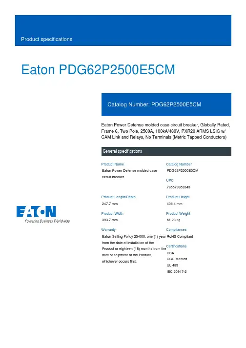
Eaton PDG62P2500E5CMEaton Power Defense molded case circuit breaker, Globally Rated, Frame 6, Two Pole, 2500A, 100kA/480V, PXR20 ARMS LSIG w/ CAM Link and Relays, No Terminals (Metric Tapped Conductors)Eaton Power Defense molded case circuit breakerPDG62P2500E5CM 786679863343247.7 mm 406.4 mm 393.7 mm 61.23 kg Eaton Selling Policy 25-000, one (1) year from the date of installation of theProduct or eighteen (18) months from thedate of shipment of the Product,whichever occurs first.RoHS Compliant CSACCC MarkedUL 489IEC 60947-2Product NameCatalog Number UPCProduct Length/Depth Product Height Product Width Product Weight WarrantyCompliancesCertifications2500 AComplete breaker 6Two-polePD6 Global Class A PXR 20 LSIG w/ARMSCAM Link600 Vac600 VNo Terminals100 kAIC at 480 Vac 100 kAIC Icu/ 50 kAIC Ics/ 220 kAIC Icm @380-415V (IEC) 100 kAIC @480/277V (UL)100 kAIC Icu/ 50 kAIC Ics/ 220 kAIC Icm @440V (IEC) 65 kAIC @600/347V (UL) 200 kAIC @240V (UL)85 kAIC Icu/ 40 kAIC Ics/ 187 kAIC Icm @480V Brazil (IEC) 35 kAIC Icu/ 18 kAIC Ics/ 73.5 kAIC Icm @690V (IEC)40 kAIC Icu/ 25 kAIC Ics/ 84 kAIC Icm @525V South Africa (IEC)200 kAIC Icu/ 100 kAIC Ics/ 440 kAIC Icm @240V (IEC)2500 AEaton Power Defense PDG62P2500E5CM 3D drawingAmperage Rating Circuit breaker frame type Frame Number of poles Circuit breaker type Class Trip TypeCommunication Voltage rating Voltage rating - max Terminals Interrupt rating Interrupt rating rangeTrip rating 3D CAD drawing packageApplication notesPower Xpert Protection Manager x32Consulting application guide - molded case circuit breakersPower Xpert Protection Manager x64BrochuresPower Defense molded case circuit breaker selection posterPower Defense brochurePower Defense technical selling bookletCatalogsPower Defense molded case circuit breakers - Frame 6 product aid Power Xpert Release trip units for Power Defense molded case circuit breakersMolded case circuit breakers catalogCertification reportsPDG6 CB reportPDG6 CCC certificatePower Defense Declaration concerning California’s Proposition 65PDG6 UL AuthorizationPDG6 CSA certificationPDG5 CCC certificationEU Declaration of Conformity - Power Defense molded case circuit breakersInstallation instructionsPower Defense Frame 6 bar rear connectors (copper), 2000A - 5000A instructions - IL012256EN H01Power Defense Frame 6 flex shaft handle mech assembly instructions - IL012285ENPower Defense Frame 2/3/4/5/6 voltage neutral sensor module wiring instructions – IL012316ENPower Defense Frame 6 modbus and relay board installation -IL012306ENPower Defense Frame 6 key interlock installation instructions -IL012282ENPower Defense Frame 6 walking beam interlock installation instructions - IL012286ENPower Defense Frame 6 aux, alarm, shunt trip and uvr instructions -IL012202ENPower Defense Frame 6 handle lock hasp installation instructions -IL012292ENInstallation videosPower Defense Frame 6 Trip Unit Replacement Animated Instructions Power Defense Frame 6 Aux, Alarm, ST and UVR Animated Instructions.rh Power Defense Frame 6 Aux and Alarm Trip How-To VideoPower Defense Frame 6 Shunt Trip How-To VideoPower Defense Frame 6 UVR Trip How-To VideoMultimediaPower Defense Frame 5 Trip Unit How-To VideoPower Defense Frame 6 Trip Unit How-To VideoPower Defense BreakersPower Defense molded case circuit breakersPower Defense Frame 2 Variable Depth Rotary Handle Mechanism Installation How-To VideoEaton Power Defense for superior arc flash safetyPower Defense Frame 3 Variable Depth Rotary Handle Mechanism Installation How-To VideoSpecifications and datasheetsEaton Specification Sheet - PDG62P2500E5CMTime/current curvesPower Defense time current curve Frame 6 - PD6White papersMaking a better machineIntelligent power starts with accurate, actionable dataImplementation of arc flash mitigating solutions at industrial manufacturing facilitiesSingle and double break MCCB performance revisitedIntelligent circuit protection yields space savingsMolded case and low-voltage power circuit breaker healthMolded case and low-voltage breaker healthSafer by design: arc energy reduction techniquesEaton Corporation plc Eaton House30 Pembroke Road Dublin 4, Ireland © 2023 Eaton. All Rights Reserved. Eaton is a registered trademark.All other trademarks areproperty of their respectiveowners./socialmedia。
Pantum P2500/P2500W黑白雷射單功能印表機建議使用前仔細閱讀本指南前言歡迎您使用奔圖系列產品!對您使用奔圖系列產品我們表示衷心的感謝!為了保障您的切身權益,請認真閱讀下麵的聲明內容。
法律說明商標Pantum 和 Pantum 標示是珠海奔圖電子有限公司的註冊商標。
Microsoft®、Windows®、Windows server®和 Windows Vista®是微軟公司在美國和其他國家注冊的商標。
Apple, AirPrint and Mac are trademarks of Apple Inc, registered in the U.S. and other countries. Use of the Works with Apple badge means that an accessory has been designed to work specifically with the technology identified in the badge and has been certified by the developer to meet Apple performance standards.Mopria®, the Mopria®Logo, and the Mopria Alliance ™word mark and logo are registered and/or unregistered trademarks and service marks of Mopria Alliance, Inc. in the United States and other countries. Unauthorized use is strictly prohibited.Wi-Fi Direct、Wi-Fi Protected Setup(WPS)、WPA、WPA2和Wi-Fi Protected Access是Wi-Fi Alliance的商標。

第五章 定期维护为避免由于误操作而导致机器损坏, 在维护工作中应按以下要求执行.警告(1) 拆卸打印机内部零件前,必须先关闭电源开关,拔掉电源插头.(2) 打印机运行后,内部有些部件温度很高. 在打开打印机前盖或后盖拆取打印机内部零件时, 千万不要触摸下图中的阴影部分,以免被烫伤.1. 耗材以下所示的耗材,指在机器的无故障周期内由于老化或损耗至少需要更换一次的零部件.1.1 硒鼓当 Drum 灯亮时,表示硒鼓组件已经快接近使用寿命了. 预期寿命:10,000 页注释:决定硒鼓实际使用寿命的因素很多, 例如 温度、 湿度、 纸张类型和所使用的墨粉以及每次打印作业的打印量等等.<耗材更换步骤>(1) 打开打印机前盖,取出硒鼓组件. (2) 将硒鼓组件放平, 然后按下右手边的锁杆,从硒鼓组件中取出墨粉盒. (Fig. 5-1) (3) 打开新硒鼓的包装.Fig. 第五章-1(4) 将墨粉盒装入新硒鼓中,当听到卡嗒的响声表明墨粉盒已经就位,当墨粉盒安装正确时,锁杆会自动抬起.(Fig. 5-2) (5) 将新硒鼓组件装入打印机中. 打开前盖,打开打印机开关,此时 drum 灯和Alarm 灯亮.Fig. 第五章-2(6) 按住控制面板按钮,直到所有的灯都亮. (显示灯从上向下顺序亮.) 此时硒鼓页数计数器既被复位. (7) 关闭前盖, 此时 Drum 灯应关闭.警告:• 必须使用 联想 生产的专用墨粉. 打印机必须在清洁、无尘、通风良好的环境中使用. • 只有当使用时再打开硒鼓组件的包装. 如果开包的硒鼓受阳光或灯光直接照射,会对硒鼓造成伤害. • 用手拿硒鼓和墨粉盒时应特别注意. 如果墨粉粘在手上或衣服上,应立刻用冷水将其清洗干净. • 当仅仅更换墨粉盒时,不要复位计数器.1.2 墨粉盒墨粉低显示: 每隔 5 秒钟 Data 和 Alarm 灯闪一次. 缺粉显示: Data 和 Alarm 灯每秒闪一次.预期寿命: 3,000 页/标准墨粉盒 6,000 页/大容量墨粉盒(打印 A4- 或 Letter-纸, 5% 打印覆盖率)注释:决定墨粉盒实际使用寿命的因素很多, 例如 温度、 湿度、 纸张类型以及每次打印作业的打印量等等.<更换墨粉盒步骤>(1) 打开前盖,取出硒鼓组件.(2) 将硒鼓放平, 按下右手侧的锁杆,取出墨粉盒. (3) 打开新墨粉盒包装,将墨粉盒轻轻的沿水平方向摇动 5 ~ 6 次. (Fig. 5-3)Fig. 第五章-3(4) 取下保护盖. (Fig. 5-4)(5) 将新墨粉盒装入硒鼓中,当听到卡嗒的响声表明墨粉盒已经就位,当墨粉盒安装正确时,锁杆会自动抬起.Fig. 第五章-4(6) 左右拉动电晕丝清洁滑块,清洁硒鼓组件中的电晕丝 (Fig. 5-5) (7) 将清洁滑快归位.(8) 将硒鼓组件装入打印机中,关闭打印机前盖.Fig. 第五章-5警告:• 更换墨粉盒时,应将硒鼓组件水平放置,以避免墨粉漏出.• 用手拿硒鼓和墨粉盒时应特别注意. 如果墨粉粘在手上或衣服上,应立刻用冷水将其清洗干净.• 只有当使用时再打开墨粉盒包装,打开包装的墨粉盒长期不用,也会减少墨粉寿命. • 开包的硒鼓受阳光或灯光直接照射,会对硒鼓造成伤害. • 只有使用本机指定使用的专用墨粉,才能保证打印质量.• 使用杂牌墨粉不仅会降低打印质量,还会降低打印机的使用寿命.• 清洁完电晕丝后,清洁滑快一定要归位否则会造成打印黑道. (Refer to Fig. 5-5.) • 取下保护盖后,应立刻安装墨粉盒.严禁用手触摸显影辊和感光鼓(如图中阴影部分所示);Fig. 第五章-62.定期更换部件定期更换部件是指为保证打印质量需要定期更换的部件. 这些部件一旦失效对打印质量影响非常大,(即使没有完全损坏或从外表看并未有改变)下表所示为需要定期更换部件及其更换周期. 更换方法,参见第四章“拆卸和重新组装”.注释:上表所列数值,为估算值.如有更改,恕不另行通知.3.定期清理为防止打印机故障或打印图象故障,应对下列部件定期进行清理.小心:硒鼓组件和扫描器窗口的清理可由用户直接操作, 打印机内部和硒鼓上的触点和接头应由维修工程师处理. 告戒用户不要触摸这些部位.3.1 清洁打印机外部清洁打印机外部,保证打印机的清洁干净.1)关闭电源开关,拔下电源线.2)用湿布将打印机外部的灰尘和污物擦掉,等打印机干透后再打开电源开关.警告:用水或中性清洁剂进行清洁. 用酒精等挥发性液体会对打印机表面造成伤害.3.2 清洁硒鼓组件当更换硒鼓组件或更换新墨粉盒后,一定要清洁硒鼓.1)关闭打印机开关,拔掉电源线.2)取出硒鼓组件.3)用电晕丝清洁滑块清洁电晕丝清洁滑快位置 (s)Fig. 第五章-74)将清洁滑快归位小心:清洁后,清洁滑快一定要归位,否则会引起打印黑带.5)将硒鼓组件装入打印机中.3.3 清洁激光扫描器窗口当更换新硒鼓或新墨粉盒后,一定要清洁激光扫描器窗口.1)关闭电源开关,拔掉电源线.2)取出硒鼓组件.3)用干净的软布轻轻擦拭激光扫描器窗口 (下图中箭头所指的深色区域) .Fig. 第五章-8警告:•不要用手指触摸激光扫描器窗口.•不要用酒精清洁激光扫描器窗口.3.4 清洁触点更换硒鼓或墨粉后,一定要清洁打印机内的触点.4)关闭电源开关,拔掉电源线.5)取出硒鼓组件.6)用干净的软布(干布)轻轻擦拭触点 (下图中箭头所指的深色区域) .Fig. 第五章-94.平均故障周期 / 平均维修周期本打印机的平均故障间隔周期和平均故障维修时间如下:平均故障周期: 4,000 小时平均维修时间: 大约 30 分钟。

奔图CP2506DN PLUS 多功能彩色激光打印机目录1—注意事项、约定和安全信息 (1)激光注意事项 (1)惯例 (1)安全信息 (1)一般注意事项 (2)2——一般信息 (3)打印机模型配置 (3)查找序列号 (3)纸托架 (3)支持纸张尺寸 (3)支持纸张类型 (6)支持的纸张重量 (7)检修工具 (9)3——诊断和故障排除 (10)故障排除概述 (10)初始故障排查 (10)修复打印质量问题 (11)初始打印质量检查 (11)解决打印质量问题使用的耗材 (11)模糊打印检查 (13)颜色偏差检查 (15)碳粉易擦除检查 (16)灰色或纯色背景检查 (18)纯彩色或黑色图像检查 (21)空白页检查 (24)I水平彩色线/带检查 (29)文本或图像切断检查 (31)杂点杂斑检查 (33)垂直白线检查 (36)鬼影检查 (38)黑印检查 (41)缺少色彩检查 (45)墨色浓度不均匀检查 (50)重复故障检查 (52)墨迹浅淡检查 (55)打印歪斜检查 (59)碳粉斑点感应检查 (61)自动对齐检查 (65)卡纸 (68)避免卡纸 (68)卡纸位置确定 (70)纸盘卡纸 (71)A门卡纸 (71)标准纸槽卡纸 (74)多功能进纸器卡纸 (74)手动进纸器卡纸 (75)200卡纸 (77)202卡纸 (81)231卡纸 (90)232卡纸 (97)24y卡纸 (98).y信息 (105)II31.y错误 (106)32.y错误 (107)33.y错误 (107)34.y错误 (110)42.y错误 (110)43.y错误 (111)80.y错误 (112)82.y错误 (113)84.y错误 (115)88.y错误 (116)非耗材.y错误 (117)打印机硬件错误 (127)100错误 (127)110错误 (128)120错误 (130)121错误 (132)126错误 (138)142错误 (139)151错误 (141)160错误 (142)161错误 (144)162错误 (146)163错误 (146)166错误 (147)167错误 (147)171错误 (148)600错误 (149)III620错误 (151)642错误 (151)651错误 (152)661错误 (152)662错误 (153)663错误 (153)666错误 (154)667错误 (154)启动9yy维护检查前的步骤 (154)900错误 (156)91y错误 (164)938错误 (167)95y错误 (167)96y错误 (171)97y错误 (172)980-984错误 (175)99y错误 (176)其他症状 (177)基础款打印机症状 (177)输入选件症状 (200)4——维护菜单 (241)控制面板使用 (241)奔图CP2506DN PLUS (241)电源开关和指示灯状态说明 (242)主屏幕使用 (242)配置盖门互锁旁通跳线 (243)“诊断”菜单 (245)IV报告 (245)高级打印质量样页 (245)事件日志 (246)纸盘快速打印 (247)打印机设置 (247)打印机诊断和调整 (249)附加纸盘诊断 (252)配置菜单 (254)维修工程师菜单 (258)进入无效引擎模式 (258)进入维修工程师菜单 (258)总维护工程师 (258)网络维护工程师 (258)5——部件拆卸 (260)数据安全须知 (260)确认打印机内存 (260)擦除打印机内存 (260)拆卸注意事项 (261)操作ESD敏感部件 (261)控制板/控制面板的更换 (262)更换控制板后恢复打印机配置 (262)恢复解决方案、许可证和配置设置 (263)更新打印机固件 (263)备份eSF解决方案和设置 (264)断开带光缆 (265)排线接头 (265)调整 (275)V输入TPS特征数据 (278)拆卸程序 (279)拆卸左侧 (280)拆卸左侧盖板 (280)电机(驱动设备)的拆卸 (281)拆卸EP驱动组件 (282)低压电源的拆卸 (285)拆卸传感器(定影器出口) (287)拆卸右侧 (294)右上盖的拆卸 (294)加粉盖拆卸 (295)电机(定影器驱动)的拆卸 (296)TMC卡的拆卸 (297)传感器(碳粉斑点)的拆卸 (300)详见移除显影组件。
Figure . Removing the imaging unit1. Remove one 3-mm panhead screw from the lower hand-hold of the side cover shown in Figure 2, top photo.2. Pull outward slightly at the base to free the side cover at the bot-tom.3. Lift the front edge of the side cover to unhook plastic latches along the top edge of the side cover. Figure 2, bottom photo.Removing I/O cover1. Unhook the plastic latch at theFigure . Removing the right side cover Side Cover Screw Locationtop of the I/O cover as shown in Figure 3, left photo.2. Using your finger, unhook the plastic latch at the inside top I/O position under the rear cover. Figure 3, left photo.3. Pull the I/O cover rearward at the top and lift the cover from the foot at its bottom. Figure 3, right photo.Removing rear cover1. Pry under the plastic latch, one at each upper corner of the rear cover as shown in the upper photo of Figure 4.2. Rotate the top of the rear cover back, then lower the cover from the machine as in the lower photo of Figure 4.Removing top cover1. Open the top cover and unhook the tab on the cover rack gear shown in Figure 5 and removeFigure 3. R emoving t he I /O c over f rom t he HP Color LaserJet 1500/2500/2550.3the gear from below the rack.2. Free the top cover rack from its guide pin.3. Remove three top cover screws, one on the left and two on the right as shown in Figure 6.4. Lift up on the top cover as-sembly and remove it from the machine.Re indexing carousel gears1. Locate the rotary drive assembly solenoid at the top right of the printer, shown in Figure 7.2. Using a small tool as shown in Figure 7, lift and suspend the so-lenoid plate to release the carousel lock.3. While holding the rotary drive as-Figure 5. Tab (arrow) to release for ➡Figure 6. Removing three screws (one shown by the white arrow on the right ➡4move the carousel to the position 4. Under each side of the carousel, observe the indexing marks as shown in Figure 9.NOTE: Each side must be in-dexed according to Figure 9. Chances are one or both are indexed incorrectly based on the original symptoms.Figure 7. Releasing the rotary drive as-➡Solenoid5. Grasp the black carousel gear and pull it inward while push-ing outward on the white gear. When the gears separate enough to skip teeth, rotate the white gear around in the proper direction to correctly index the carousel.6. Repeat Step 5 for the opposite side of the carousel if needed.7. Recheck indexing and repeat Step 5 for correction if needed.8. Reassemble the printer and test.Figure 8. Rough carousel indexing prior Figure 9. Correct carousel indexing for ➡➡➡➡➡➡。
PGX-2500SP 操作说明书第2版2002年08月30日目录1.安全上的注意点 4 2.模式按键 7 3.手柄动作键 8 4.Jog操作动作 8 5.X・Y原点设定键 9 6.投影机键 9 7.NC模式键 9 (1)单一程序 10 (2)试运行 10 (3)程序跳移 10 (4)M功能锁定 10 (5)手动绝对坐标ABS 10 (6)快速移动调节旋钮 11 (7)选择性停止 11 (8)机械锁定 11 (9)自动停止 11 (10)自动全停止 12 (11)回归零 12 8.画面表示键 16 9.LITP・CITP键 17 10.EC重置键 17 11.LED表示 17 (1)运转准备 17 (2)NC出错 18 (3)EC出错 18 (4)OT出错 18 (5)M02/M30 18 (6)M00/M01 18 12.MDI键 19 13.动作指令开关类 20 14.辅助功能(M指令) 23 15.机台出错信息及对策 24 16.关于油路出错的说明 25 18.操作上的注意点 26 19.画面操作说明书 27和井田PGX-2500操作安全注意事项概要:本说明书是为了使购入的机台更安全地使用,我公司对该机台诸多注意事项的说明,根据所使用的机台有些没有的机能相对应的注意事项,敬请谅解。
本机台是由危险电压、旋转部位、驱动部位等装置构成,如果不遵守安全注意事项,有可能会导致人员的重轻伤或机台以外的部件损伤。
充分考虑到本机的安全性,机台使用或操作的错误,会导致致命的事故。
为了避免这些危险,在使用机器之前,请注意阅读本书以及机器和各功能用的说明书。
要充分理解。
对于本书或者操作说明书有疑问或不清楚的事项,请跟本公司联系。
在问题没有得到解决之前,不要对机器进行操作。
1.为了您的安全作业1.1注意事项照操作说明书的顺序操作机器。
如果有些内容没有涉及,请不要随便操作。
¤首先需要理解存在潜在危险的内容和场所,然后想出相应的对策。
Do not open the ink bottles until you are ready to fill the ink tanks. The ink bottles are vacuum packed to maintain reliability.emove all protective materials from the product.11 P ress thebutton for 3 seconds until the power lightstarts flashing, to begin charging the ink. Ink charging takes approximately 20 minutes. Ink charging is complete when thepower light stops flashing.20 minutesNote: The ink bottles included with the printer are designed for printer setup and not for resale. After some ink is used for charging, the rest is available for printing.Caution: Do not turn off the product or load paper while theproduct is charging or you’ll waste ink.1 M ake sure the product is not charging. Then flip thefeeder guard forward, raise the paper support, and tilt itbackwards slightly.2 S lide the edge guide to the left.3 L4 SMobile printing optionsTo print from a mobile device, your product must be set up forwireless printing or Wi-Fi Direct ®. See the online User’s Guide for instructions.iOS/Android ™Epson Connect™Connect wirelessly from your tablet, smartphone, or computer. Print documents and photos from across the room or around the world./iprint /connectAny problems?Network setup was unsuccessful.• M ake sure you select the right network name (SSID). Theproduct can only connect to a network that supports 2.4 GHz.• I f you see a firewall alert message, click Unblock or Allow to let setup continue.• I f your network has security enabled, make sure you enter your network password (WEP key or WPA passphrase) correctly. Passwords must be entered in the correct case.There are lines or incorrect colors in my printouts.Run a nozzle check to see if any of the print head nozzles are clogged. Then clean the print head, if necessary. See the online User’s Guide for more information.Setup is unable to find my product after connecting it with a USB cable.Make sure the product is on and securely connected as shown:5 P ull out the output tray and raise the paper stopper.Note: If your computer does not have a CD/DVD drive or you are using a Mac, an Internet connection is required to obtain the product software.1 M ake sure the product is NOT CONNECTED to yourcomputer.W indows ®: If you see a Found New Hardware screen, click Cancel and disconnect the USB cable.2I nsert the product CD or download and run your product’ssoftware package:/support/et2500 (U.S.) or epson.ca/support/et2500 (Canada)3 F ollow the instructions on the screen to run the setupprogram.OS X: Make sure you install Software Updater to receive firmware and software updates for your product.4 W hen you see the Select Your Connection screen, selectone of the following:• Wireless connectionIn most cases, the software installer automatically attempts to set up your wireless connection. If setup is unsuccessful, you may need to enter your network name (SSID) and password.• Direct USB connectionM ake sure you have a USB cable (not included).5 W hen software installation is complete, restart yourcomputer.。