GE E-CELL模块用户手册
- 格式:pdf
- 大小:2.78 MB
- 文档页数:31


操作手册FOR THE120 GPM, 27.3 m3/hE-CELL SYSTEM TM注意:本手册含有对 E-Cell 公司所提供的水处理系统的操作和维护指导。
在操作和维修该系统时,必须始终遵守手册中的程序。
此中文文本的内容与英语版本的用户手册有分歧时,以英文版本为准。
1. 人身安全注意事项E-CELL MK-2 STACK™1.1 电气1. 定期检查接线端子是否接触良好。
2. 如发现有损坏的电气元件,在修复或更换前要先隔离该元件。
3. 检查电器箱密封良好以防进水。
4. 只允许有资格的电气技术人员进行检修工作。
5. 整流器处于工作状态时不可切断E-Cell MK-2模块上的电源线。
1.2 机械E-Cell MK-2 模块含有电器元件,可能造成触电危险,故请勿将工具、螺丝等放置在E-Cell 模块上。
除专业人员外,不要调整E-Cell MK-2 模块上的螺丝。
模块端板间的距离在出厂前已经精确调节,过度调整可能造成永久损害。
1.2.1 泄漏MK-2 模块的最大操作压力是 100 psi (6.8 bar) ,在正常压力下模块不应泄漏。
如发现模块漏水,应停机检查泄漏位置和模块端板间距。
若漏水无法解决,请立即联系E-Cell 公司。
1.2.2 离心泵1. 严禁在运转的离心泵上工作。
如需维护必须停机并在泵上加标识。
2. 确保水泵电机风扇的通风畅通。
1.2.3 水力E-Cell™ 系统通过不同管径的管道输送大量的水,如非正常的操作可能引起设备损坏、高压水泄漏以致人身伤害。
1. 确认所有的管道都有足够的固定和支撑。
2. 在开启系统进水阀门前,保证出口阀门已经开启。
1.3 停机必须遵守停机程序来保证工作人员的安全。
不仅需注意转动设备和电器,对容器或水管也应小心。
1.4 通道在 E-Cell™ 设备周围应有足够的通道和照明以便操作和维护的安全。
1.5 安全用具当可能暴露在酸碱环境中时,须穿戴橡胶手套、橡胶服、面罩和防护眼镜。

GEGrid Solutionsimagination at workInnovative Technology& Design• Advanced feeder One Box Solution for protection, control monitoring anddiagnostics of single/dual feeder applications Feeder and Bay Controller Solutions for Industrial and Utility ApplicationsThe Multilin™ 850 relay is a member of the Multilin 8 Series protective relay platform and has been designed for the management, protection and control of feeder applications. The Multilin 850 is used to provide primary (main) or backup protection for underground and overhead single or dual feeders for utility and industrial power networks.With 11 Switchgear control elements, fully configurable Single Line Diagram on a large color graphical display, 36 alarm integrated annunciator panel and 20 push buttons makes the 850 the ideal choice for bay control and protection as a “One Box Solution”.Designed with advanced communications options and detailed asset monitoring capabilities, the Multilin 850 provides advanced functionality, including high-performance protection, extensive programmable logic and flexible configuration capabilities. With support for industry leading communications protocols and technologies, the 850 provides easy integration into new or existing SCADA or DCS for enhanced situational awareness.Key Benefits• One Box Solution with advanced logic and configuration flexibility, providing primary or backup protection for up to 2 feeders or feeders with 2 sets of voltage inputs • User configurable Single Line Diagram on color display for local control, system status, and metering • Advanced breaker diagnostics with comprehensive fault and disturbance recording• Integrated arc flash detection using light sensors supervised by overcurrent to reduce incident energy and equipment damage • Advanced cyber security features including AAA, Radius, RBAC, and Syslog enabling NERC ® CIP requirements • Draw-out design simplifies testing, commissioning and maintenance, increasing process uptime • Patented environmental monitoring, providing visibility to changes in environmental conditions that can affect relay lifeApplications• Single/dual feeder applications for utility, oil & gas, mining & metals, process industry, commercial, and waste water segments • Fast protection pass enabling load shedding schemes • Reliable automatic bus transfer & autoreclose schemes • Bay controller for wide range of switchgear applications • High speed fault detection for arc flash mitigationMultilin 850WARRANTYYEAR850Multilin 850 OverviewThe Multilin 850 is an advanced feeder protection device designed for high performance, protection, control and monitoring of incoming and outgoing feeders.With up to 57 digital inputs and 22 digital outputs in a compact box, the 850 provides a versatile and cost effective control, protection, measurement & monitoring solution. Flexelements and Flexlogic enable users to customize schemes to meet a variety of applications.From dual main to main-standby configurations, the Multilin 850D delivers a more economical and reliable solution, enabling customers to reduce hardware requirements and simplify device integration, including safe and secure Wi-Fi communications for system configuration and diagnostics. Bay Controller/One Box SolutionThe 850 offers comprehensive switchgear control aided by a configurable Single Line Diagram & breaker control. A total of 10 switchgear elements can be displayed and 8 elements controlled. The integrated solution for protection, control, monitoring and diagnostics eliminates the need for other external devices thus offering an integrated solution for switchgear systems. The device supports 6 user programmable pages. The Multilin 850 is an integrated solution that performs protection, control & monitoring of assets, and ease of retrieval of fault & event records. Coordinating remotely with SCADA over multiple communication protocols gives the Multilin 850 an added advantage for fast and efficient management of fault isolation and service restoration.The Multilin 850 is a cost-effective retrofit solutions where individual components of protection, metering, control switches, annunciator & panel mimic can be replaced by only one relay. Switchgear Control and Configurable SLDThe Multilin 850 provides a configurable dynamic SLD up to six (6) pages for comprehensive switchgear control of up to 2 breakers and 9 disconnect switches; including interlocks. Up to 15 digital and metering status elements can be configured per SLD page. These can be configured to show breakers, switches, metering, and status items.Individual SLD pages can be selected for the default home screen pages. Automatic cycling through these pages can also be achieved through default screen settings.The provision of such powerful control and display capability within the relay (“One Box” concept) eliminates the need for external controls, switches and annunciation on the panel reducing equipment and engineering cost. Annunciator Panel and Virtual Push ButtonsThe Multilin 850 offers a configurable annunciator panel that can be constructed to show up to 36 alarms in either self-reset mode or latched mode per ISA 18.1 standard similar to a physical annunciator panel; eliminating the need for a physical one. This removes the need for additional programmable LEDs. The alarms can be displayed on the front panel in a configurable grid layout of 2x2 or 3x3.The Multilin 850 extends the local control functionalities with 20 virtual pushbuttons that can be assigned for various functions. Each programmable pushbutton has its own programmable LED which can be used to acknowledge the action taken by the tab pushbutton.With a fast protection pass, running every 2 msec, the 850 relay provides fast response to current, voltage, power, and frequency protection elements; helping reduce stress on assets. The Multilin 850 supports the latest communication protocols, including DNP, ModBus, IEC 60870-5-103, IEC 62439/PRP and IEC 61850; facilitating easy integration into new or existing SCADA/DCS networks.Functional Block Diagram850 Distribution FeederWith support for up to 8 CT inputs & 2 sets of 4 traditional VT inputs, the 850 can be used for 2 feeders or feeders with 2 sets of voltage inputs, simplifying system architectures and operational costs.The 850 offers redundancy with the same number of devices, enabling:Architecture Simplification - Reduced Number of Devices• Less capital cost • Less O&M costMean Time to Repair - Less than 15 minutes• Field swappable PSU • Draw out construction• Ready to consume service reportsExtended Asset and Relay Life• Built-in Environmental monitoring • Advanced breaker monitoring• TGFD and Cable incipient fault detection/locationSimplified Management - Platform Based Solution• Reduced training needs• Standardized part number across systems • Harmonized look and feel, operational experienceProtection & ControlAs part of the 8 Series family, the Multilin 850 provides superior protection and control. The 850 offers comprehensive protection and control solutions for incoming, outgoing bus-tie/bus-coupler feeders. It contains a full range of selectively enabled, self-contained protection and control elements.The voltage and frequency protection functions detect abnormal system conditions, potentially hazardous to the system. Some of these conditions may consist of over and undervoltage, over and underfrequency, and phase reversal.Fast UnderfrequencyThe 850 has an 8 stage Fast Underfrequency element that measures frequency by detecting the consecutive voltage zero crossings and measuring the time between them. The measured frequency has a range between 20 to 70 Hz. This is useful for performing fast load-shedding when frequency variations from unbalance conditions arise due to:• Inadequate load forecast or deficient generation capacity programming.• Busbars, generator group or interconnection feeders trip.• System splits into islands.FlexCurves™For applications that require greater flexibility, FlexCurves can be used to define custom curve shapes. These curves can be used to coordinate with other feeders to achieve fault selectivity.RTD ProtectionThe Multilin 850 supports up to 13 programmable RTD inputs that can be configured for an Alarm or Trip.The RTDs can be assigned to a group for monitoring ambient temperatures or any other desired temperature. The RTD voting option gives additional reliability to ignore and alarm for any RTD failures.Integrated Arc Flash ProtectionThe Multilin 8 Series supports an integrated arc flash module providing constant monitoring for an arc flash condition within the switchgear, motor control centers, or panelboards. With a 2ms protection pass, the 8 Series is able to detect light and overcurrent using 4 arc sensors connected to the relay. In situations where an arc flash/fault does occur, the relay is able to quickly identify the fault and issue a trip command to the associated breaker thereby reducing the total incident energy and minimizing resulting equipment damage.Self-monitoring and diagnostics of the sensors ensures the health of the sensors as well as the full length fiber cables. LEDs on the front panel display of the 850 can be configured to indicate the health of the sensorsand its connections to the relay.Dual feederRedundant feeder850WANT TO LEARN MORE?EXPLORE IN 3DMV SwitchgearMultilin 8 SeriesFast, reliable arc flash protection with integrated light based arc flash sensors. This delivers detection in as fast as 2 msec, reducing the costs associated with equipment damage and unplanned downtime.Inputs and OutputsThe 850 provides a max of 57 Digital inputs and 22 Digital outputs with an option for 7 Analog Outputs (dc mA), 4 Analog Inputs (dc mA), and 1 RTD input. The configurable analog inputs can be used to measure quantities fed to the relay from standard transducers. Each input can be individually set to measure 4-20 mA, 0-20 mA or 0-1 mA transducer signals.Advanced AutomationThe Multilin 850 incorporates advanced automation capabilities which exceed those found in most feeder protection relays. This reduces the need for additional programmable controllers or discrete control relays including programmable logic, communication, and SCADA devices. Advanced automation also enables seamless integration of the 850 into other protection or process systems (SCADA or DCS).FlexElements™FlexElement is a universal comparator, that can be used to monitor any (analog) actual value measured or calculated by the relay, or a net difference of any two analog (actual) values of the same type.The element can be programmed to respond either to a signal level or to a rate-of-change (delta) over a pre-defined period of time.This can be used to generate special protection or monitoring functions which allow the user to flag a user-defined abnormality to give better visibility to a certain condition.FlexLogic™FlexLogic is the powerful programming logic engine that provides the ability to create customized protection and control schemes, minimizing the need for and associated costs of auxiliary components and wiring. Using FlexLogic, the 850 can be programmed to provide the required tripping logic along with custom scheme logic for feeder control interlocking schemes with adjacent protection (for example, preventing sympathetic tripping of healthy feeders), and dynamic setting group changes.Breaker Health MonitoringThe breaker is monitored by the relay not only for detection of breaker failure, but also for the overall “breaker health” which includes:• Breaker close and breaker open times • Trip circuit monitoring • Spring charging time • Per-phase arcing current • Trip countersAll algorithms provide the user with the flexibility to set up initial breaker trip counter conditions and define the criteria for breaker wear throughouta number of set points.Breaker Health Reporting assists Condition-Based Maintenance and savings in Operational CostsMonitoring & DiagnosticsThe Multilin 850 includes high accuracy metering and recording for all AC signals. Voltage, current, and power metering are built into the relay as a standard feature. Current and voltage parameters are available as total RMS magnitude, and as fundamental frequency magnitude and angle.Environmental MonitoringThe 850 has an Environmental Awareness Module (EAM) to record environmental data over the life of the product. The patented module measures temperature, humidity, surge pulses and accumulates the events every hour in pre-determined threshold buckets over a period of 15 years. This data can be retrieved using the EnerVista Setup Software. This report helps identify the operating condition of the installed fleet so that remedial action can be taken.850Environmental health report is available via Multilin PC SoftwareMeteringThe Multilin 850 offers high accuracy power quality monitoring for fault and system disturbance analysis. It delivers unmatched power system analytics through the following advanced features and monitoring and recording tools:• Harmonics measurement up to 25th harmonic for both currents and voltages including THD.• The length of the transient recorder record ranges from 31 to 1549 cycles (typically half a second to half a minute).• 32 digital points and 16 analog values.• Comprehensive data logger provides the recording of 16 analog values.• Detailed Fault Report. The 850 stores fault reports for the last 16 events. 1024 Event Recorder.CommunicationsThe Multilin 8 Series provides advanced communications technologies for remote data and engineering access, making it easy and flexible to use and integrate into new and existing infrastructures. Direct support for fiber optic Ethernet provides high-bandwidth communications, allowing for low-latency controls and high-speed file transfers of relay fault and event record information. The 850 also supports two independent IP addresses, providing high flexibility for the most challenging of communication networks. Providing several Ethernet and serial port options and supporting a wide range of industry standard protocols, the 8 Series enables easy, direct integration into DCS and SCADA systems. The 8 Series supports the following protocols:• IEC 61850 (8 Clients, 4 Logical Devices, Tx & Rx expansion, Analog GOOSE), IEC 62439 / PRP• DNP 3.0 serial, DNP 3.0 TCP/IP, IEC 60870-5-103, IEC 60870-5-104• Modbus RTU, Modbus TCP/IPThe 850 has two interfaces, a USB front port and Wi-Fi for ease of access to the relay.Wi-Fi Connectivity:• Simplify set-up and configuration• Simplify diagnostic retrieval• Allows personnel to be a safer distance from the front of the switchgear • WPA-2 securityCyber SecurityThe 8 Series delivers a host of cyber security features that help operators to comply with NERC CIP guidelines and regulations.• AAA Server Support (Radius/LDAP)• Role Based Access Control (RBAC)• Event Recorder (Syslog for SEM)Role, User, PasswordEncrypted (SSH)Security ServerCyber Security with Radius AuthenticationPLC / Gateway850869845MM200MM300ControllersReason S20Ethernet SwitchLV Network850 Menu path display indicating location within menu structureSoft menu navigation keysLED status indicatorsGraphic ControlPanel (GCP)Navigation keysFront USB portCaptive screw prevents inadvertent or unauthorized draw-outContext-sensitive menu for fast navigation Front View - Advanced Membrane Front PanelDimensions & MountingStandard serial and RJ45 Ethernet moduleAdvanced communica-tions module (Fiber Optic or Copper ports)CT, VT inputsGrounding screwPower supplyRTDsDigital I/O, DCmA, Arc Flash sensorsRear ViewEXPLORE IN 3D8.42”9.90”1.55”7.55”Optional IP20 cover available10 User-ProgrammablePush Buttons850 850D Wiring DiagramACCESS POINT850 850E Wiring DiagramPHASE CTsDIRECTION OF POWER FLOW FOR POSITIVE WATTS POSITIVE DIRECTION OF LAGGING VARSD9C O MN NINSTRUCTION MANUALSEE VT WIRING INCONNECTIONWYE VT INSTRUCTION MANUALINPUT WIRING INSEE GROUND 52b52a850-E Industrial Feeder Protection SystemJ9 J10 J11 J12 J13 J14OPEN DELTA VT CONNECTIONN N A I G I sg I C I N B I CANRESRVD 10D8D D745CV B V A V XV X V C V B V A V COMPUTERPERSONAL COMMUNICATIONSD1D2D3D D D6S L O T ASLOTS J & KDA O L CIRCUITCLOSECIRCUITTRIP POWERCONTROL RS485COMMUNICATIONS IRIG-B SLOT F: I/O_AVOLTAGE INPUTSCURRENT INPUTSETHERNETCOMPUTERPERSONAL USBPWR SUPPLY STUDGND BUSGROUND BUS MANUALIN INSTRUCTION MONITORING CLOSE COIL SEE TRIP AND CONTROL POWERSHOWN WITH NO OUTPUT CONTACTS 52F2F1O U T P U T R E L A Y SD I G I T A L I N P U T SVVF24F23F22F12F11F10F9F8F7F6F5F4J16F3RELAYFAILURE CRITICAL AUXILIARY 3CLOSETRIPDN U O R G LA R T U E N EN I L A1A2A3J14J13J12J11J10J9J1 J2 J3 J4 J5 J6 J7 J8 K7 K8G/H2G/H1O U T P U T R E L A Y SG/H24G/H23G/H22G/H12G/H11G/H10G/H9G/H8G/H7G/H6G/H5G/H4G/H3SLOT G OR H: I/O_A* (OPTIONAL)ACCESS POINTJ15AUX VTAUXILIARY 4AUXILIARY 9AUXILIARY 10AUXILIARY 11AUXILIARY 12AUXILIARY 16DCmA I/OANALOG OUTPUTANALOG INPUTRTD12345671234ANY MEASURED OR METEREDANALOG PARAMETER OUTPUTSAMBIENTTEMPERATURE+++++++++++SLOT G: I/O_L (OPTIONAL)A R C F L A S HSLOT H: I/O_F (OPTIONAL)SLOT B OR C: I/O_R OR I/O_S* (OPTIONAL)* SUPPORTS 10 OHM COPPER RTD AS WELL* SLOT H I/O_A IS AVAILABLE WHEN SLOT G IS WITH I/O_LANY MEASURED ORMETERED ANALOG PARAMETER INPUTSCABLE SHIELD TO BE GROUNDED AT PLC/COMPUTER END ONLYRTD RTDFront PanelSLOT D**SLOT ERear PanelC O M850OrderingCONFIGURE ONLINE850* **NN *****A ************N DescriptionAAdvanced - CyberSentry Level 1Note: Harsh Environment Coating is provided as standard on all 8 series units.* HV I/O, Option A - Max 2 across slots F through HArc Flash Detection (Option F): Includes 4 x Arc Flash sensors, each 18 feet (5.5 meters) longIEC is a registered trademark of Commission Electrotechnique Internationale. IEEE is a registeredtrademark of the Institute of Electrical Electronics Engineers, Inc. Modbus is a registered trademark ofSchneider Automation. NERC is a registered trademark of North American Electric Reliability Council. NISTis a registered trademark of the National Institute of Standards and Technology.GE, the GE monogram, Multilin, FlexLogic, EnerVista and CyberSentry are trademarks of General ElectricCompany.GE reserves the right to make changes to specifications of products described at any time without notice andwithout obligation to notify any person of such changes.imagination at work GEA-32050(E)Copyright 2018, General Electric Company. All Rights Reserved.。

COMPACT and SAFERReliable top PERFORMANCEWORLDWIDE presenceELECTRICAL POWER COMPONENTS FOR YOUR MARINE APPLICATION COM PACT AND SAFER / RELIABLE TOP PERFORM ANCE / WORLDWIDE PRESENCEToday 90% of the world’s goods are transported over water. From the most advancedfrigates to the largest luxury cruise-liners and drilling rigs, we power, propel and position the marine industry.The available space on your boat is very precious. At GE we have developed and certifi ed a full range of modular devices, industrial breakers and control products that provide you excellent electrical protection while saving space on board .The environmental conditions on your ship can be very demanding with extremely hard levels of temperature and humidity, as well as strong vibrations. Through our extensive research and experience you benefi t from highly reliable power components with top performance , even under very demanding conditions .With our worldwide presence in over 140 nations you can be sure of a wide availability of complete systems and spare parts, anywhere in the world. This enables you to greatly reduce your ship’s maintenance time .ELECTRICAL POWER COMPONENTSfor your marine applicationThe space on your boat is very precious. Every area is designed to host people and goods in an optimized way. The available space for electrical power and services therefore needs to be optimized as much as possible.At the same time the electrical demands on your ship become greater and greater (e.g. communication and energy effi ciency systems), increasing the need of electrical power and services.At GE we have developed and certifi ed a full range of compact modular devices, industrial breakers and control products with a strong focus on size reduction, providing you excellent protection while you save space on board .Unibis, for example, allows you to save up to 50% on space indistribution boards.Compact and safer“ O ur range of breakers and auxiliaries provide you excellent protection in compact frames, allowing you to save space on board ina secure way.”The environmental conditions on your ship can be verydemanding. Electric devices and protections are often located in small spaces, where they reach extremely hard levels of temperature and humidity. Those conditions can change a lot depending on climate and working conditions.Moreover, vibrations caused by navigation waves and running engines are mechanically demanding for all components of your ship.Therefore the electric distribution in your ship requires devices and systems with a specifi c electrical and mechanical performance. Through our extensive research and experience you benefi t from highly reliable power components with top performance, also under very demanding conditions.With our Entelliguard G breaker, for example, we guarantee you a 2.500 A nominal current without derating up to 70°C.!While cruising for thousands of kilometers around the globe, your ship can be far away from its construction site, with very little time to stop for maintenance and very little time to wait for spare parts. With our worldwide presence in over 140 nations you can be sure of a wide availability of complete systems and spare parts, anywhere in the world. We offer a range of products with international certifi cation by all main IACS Certifi cation Societies to cover your requests all around the world.Effi cor, for example, is a global platform for contractors and thermal overload relays that has conformity to the relevant international standards.Reliable top performanceWorldwide presenceur extensive researchof complete systems andDiscover our product rangeEntelliGuard*GUnibis DPCModular components People and line protectionIndustrial breakers Main power protectionControls & PEL Power command and controlsA complete range for people and line protection with Miniature Circuit Breakers, Residual Current Devices and auxiliaries, up to 4 poles and 125 A.Including Unibis* compact range.Moulded Case Circuit Breakers, up to 1.600 A and 690Vac, and Air Circuit Breakers, up to 6.400 A and 1.000Vac.Including Entelliguard G* global ACBs line.A complete offer of Contactors, Thermal Overload Relays, Manual Motor Starters, Auxiliaries and Soft Starters.Including Efficor* contactor line with best performances.Series EP-MCBs Series EPC-MCBs Diff-o-Click RCDs CA-CBRecord PlusEffi cor relaysSurion Manual motorstartersPush-buttons Series P9Compact Soft StartersEffi corCertifi cationsOur products are certifi ed by most Classifi cation Societies that are members of The International Association of Classifi cation Societies (IACS). We can therefore guarantee you top quality and international recognition of our entire product range.Easy online availability of full range in distribution,protection and control productsGE Industrial Solutions has integratedmore than 13.000 references in the EPLAN data portal. Each product reference contains technical data, macro schemes and high quality 2D & 3D images to easily work on electrical design projects.This upload allows you to work in EPLAN Electric P8, EPLAN Pro Panel or EPLAN Engineering Center using the complete GE Industrial Solutions product basket.WorldwideIEC Solution inGE Industrial Solutions116609 GE Industrial Solutions is a fi rst class global supplier of low and mediumvoltage products including wiring devices, residential and industrialelectrical distribution components, automation products, enclosuresand switchboards. Demand for the company’s products comes fromwholesalers, installers, panelboard builders, contractors, OEMs andutilities worldwide.694550Ref. G/1420/E/EX 1.0 Ed. 09/15 /markets/marine© Copyright GE Industrial Solutions 2015。
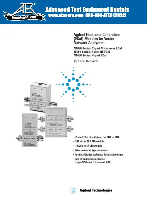
•Control ECal directly from the PNA or ENA •300 kHz to 26.5 GHz module •10 MHz to 67 GHz module •Nine connector types available•Ideal calibration technique for manufacturing •Mixed-connectors available(Type-N 50 ohm, 3.5 mm and 7-16)Agilent Electronic Calibration (ECal) Modules for Vector Network AnalyzersN4690 Series, 2-port Microwave ECal 85090 Series, 2-port RF ECal N4430 Series, 4-port ECalTechnical Overview198125. ENA series consists of E5070/1.6. ENA-L series consists of E5061/2.7.N3381/2/3 have been discontinued.8. PNA-L series consists of N5230.ECal and Agilent Network Analyzer ConfigurationsPNA and ENA SeriesECal modules are controlled directly from the PNA and ENA Series network analyzers. No external PC is required. Simply connect the ECal module to the USB port on the network analyz-er. You can control your calibra-tion from the front panel keys of the PNA Series or automatically by your user program.Calibration configuration using the PNA series3Perform adapter removal calibrations fasterSome analyzers, such as later versions of the 8753 and 8720, offer adapter removal calibration for non-insertable and mixed connector measurement capabil-ity. Since this method requires two full two-port calibrations, it is often time consuming and prone to operator errors. Using ECal to perform the two-port calibrations addresses both of these concerns by reducing the calibration time and the number of connections, simplifying the overall adapter removal process.Perform a User-characterization Normally, when you perform a calibration with an ECal module, the error terms for a calibration are computed using the factory characterization (data) stored in the module. User-characteriza-tion allows you to change the characterization of the module in two ways:• Change the connector configuration: allows you to add an adapter or fixture to the test port of the module and embed the effects into the characterization of the module. The result of the new characterization extends the reference plane from one or more of the module’s test ports to those on the adapter (or fixture).• Modify the state settings: allows you to specify the number of data points (1601 maximum) or other stimulus settings the module uses to perform a cali-bration.When you perform a user-charac-terization, the factory characteri-zation data remains stored in the module’s memory. At calibration, you can select the factory characterization or any of the user-defined characterizations stored in the module. The module can store up to five user-defined characterizations (in addition to the factory characterization data). User-characterization is available with PNA and ENA Series Network Analyzers.41. If the maximum input power is exceeded when calibrating, compression may occur.2. When using the PNA-X, the power level can be increased after calibration with minimal impact on measurement accuracy.3. When mated with male connectors with a 0.77 mm (0.030 in) to 0.86 mm (0.034 in) pin diameter51. When applied power exceeds +9 dBm, calibration results will be degraded from the performance indicated in the table.2. When applied power exceeds –5 dBm, calibration results will be degraded from the performance indicated in the table.3. 3.5 mm modules have precision slotless connectors that guarantee the best calibration accuracy is transferred to your system.61.When applied power exceeds +9 dBm, calibration results will be degraded from the performance indicated in the table.2. When applied power exceeds –5 dBm, calibration results will be degraded from the performance indicated in the table.73. Performance from 9 kHz to 300 kHz is valid only for the E5071C ENA network analyzer with firmware version A.09.10 or higher.4. 9 to 13.5 GHz range not vaild for the N4431A81. When applied power exceeds –7 dBm, calibration results will be degraded from the performance indicated in this table.2. Values based on using the PNA Network Analyzer N5230A Option 240 or 245910Ordering informationSelect an ECal module based on the connector type required and the frequency range of your vector network analyzer (refer to table below).OptionsOption Description00F Replace f-m connectors on ECal module(s) with f-f connectors 00M Replace f-m connectors on ECal module(s) with m-m connectors00A Adds male-to-male and female-to-female adapters (also adds a 5/16” 90 N-cm (8 in-lb) torque wrench to 3.5 mm modules)1A7ISO 17025 compliant calibration A6J ANSI Z540 compliant calibrationUK6Commercial calibration certificate with measured data M0F f-m connectors on ECal module(s)010Four female, 3.5 mm connectors 020Four female, Type-N 50 ohm connectorsECal modules and available options2-portConnector Frequency range ECal module Available options Type model number Type-F300 kHz to 3 GHz85099C 00A, 00F, 00M, UK6, M0FType-N 300 kHz to 9 GHz 85092C00A, 00F, 00M, UK6, 1A7, A6J, M0F,50 ohms mixed-connectorsType-N 300 kHz to 18 GHz N4690B00A, 00F, 00M, UK6, 1A7, A6J, M0F 50 ohmsType-N 300 kHz to 3 GHz 85096C 00A, 00F, 00M, UK6, M0F75 ohms3.5 mm 300 kHz to 9 GHz85093C00A, 00F, 00M, UK6, 1A7, A6J, M0F mixed connectors3.5 mm 300 kHz to 26.5 GHz N4691B 00A, 00F, 00M, UK6, 1A7, A6J, M0F 7 mm 300 kHz to 9 GHz 85091C UK6, 1A7, A6J 7 mm 300 kHz to 18 GHz N4696BUK6, 1A7, A6J7-16 300 kHz to 7.5 GHz 85098C 00A, 00F, 00M, UK6, M0F, mixed-connectors 2.92 mm 10 MHz to 40 GHz N4692A 00A,00F, 00M, UK6, 1A7, A6J, M0F 2.4 mm 10 MHz to 50 GHz N4693A 00A,00F, 00M, UK6, 1A7, A6J, M0F 1.85 mm10 MHz to 67 GHzN4694A00A,00F, 00M, UK6, 1A7, A6J, M0F4-portConnector Frequency range ECal module Available options Type model number 3.5 mm or 9 kHz to 13.5 GHz N4431B010, 020, UK6, 1A7, A6J, mixed-connectorsType-N 50 ohms Type-N 300 kHz to 18 GHz N4432A 020, mixed-connectors 50 ohms 3.5 mm300 kHz to 20 GHzN4433A010Notes:1. Order the 85097B interface module if you will be using ECal with your 8719, 8720, 8722 or 8753. (Please reference the ECal and network analyzer/firmware compatibility table on page 3.) The 85097B con-sists of an interface module and a power supply.2.When using the N469x ECal prod-ucts with the 8720 or 8753 network analyzer families, an adapter cable (8121-1047) is needed. This adapter cable is orderable as an option with the 85097B.1.Performance from 9 kHz to 300 KHz is valid only for the E5071C ENA network analyzer with firmware version A.09.10 or higher.1111.Limits ECal module high frequency to 7.5 GHz.Remove all doubtOur repair and calibration services will get your equipment back to you, performing like new, when prom-ised. You will get full value out of your Agilent equipment through-out its lifetime. Your equipment will be serviced by Agilent-trained technicians using the latest factory calibration procedures, automated repair diagnostics and genuine parts. You will always have the utmost confidence in your measurements. For information regarding self maintenance of this product, please contact your Agilent office.Agilent offers a wide range of ad-ditional expert test and measure-ment services for your equipment, including initial start-up assistance, onsite education and training, as well as design, system integration, and project management.For more information on repair and calibration services, go to:/find/removealldoubt/find/emailupdatesGet the latest information on theproducts and applications you select./find/agilentdirectQuickly choose and use your testequipment solutions with confidence./find/openAgilent Open simplifies the process of connecting and programming test systems to help engineers design, validate and manufacture electronic products. Agilent offers open connectivity for a broad range of system-ready instruments, open industry software, PC-standard I/O and global support, which are combined to more easily integrate test system development.For more information on Agilent Technol-ogies’ products, applications or services, please contact your local Agilent office. The complete list is available at:/find/contactus Americas Canada(877) 894-4414Latin America 305 269 7500United States (800) 829-4444Asia Pacific Australia 1 800 629 485China800 810 0189Hong Kong 800 938 693India 1 800 112 929Japan 0120 (421) 345Korea 080 769 0800Malaysia 1 800 888 848Singapore 180****8100Taiwan 0800 047 866Thailand1 800 226 008Europe & Middle East Austria 01 36027 71571Belgium 32 (0) 2 404 93 40 Denmark 45 70 13 15 15Finland 358 (0) 10 855 2100France 0825 010 700**0.125 €/minuteGermany ************Ireland 1890 924 204Israel 972-3-9288-504/544Italy 39 02 92 60 8484Netherlands 31 (0) 20 547 2111Spain 34 (91) 631 3300Sweden 0200-88 22 55Switzerland 0800 80 53 53United Kingdom 44 (0) 118 9276201Other European Countries:/find/contactusRevised: October 6, 2008© Agilent Technologies, Inc. 2002-2009Printed in USA, February 3, 20095963-3743EWindows ®and Windows NT ®are U.S. registered trademarks of Microsoft Corp.Product specifications and descriptions in this document subject to change without notice.Web ResourcesVisit our Web sites, for additional product information and literature.Electronic calibration (ECal):/find/ecalPNASeries network analyzers:/find/pnaTest and measurement accessories:/find/accessories。
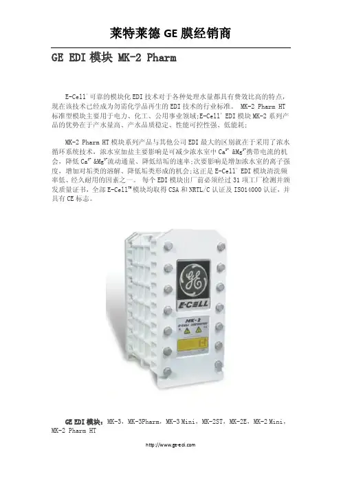
GE EDI模块 MK-2 PharmE-Cell® 可靠的模块化EDI技术对于各种处理水量都具有费效比高的特点,现在该技术已经成为勿需化学品再生的EDI技术的行业标准。
MK-2 Pharm HT 标准型模块主要用于电力、化工、公用事业领域;E-Cell® EDI模块MK-2系列产品的优势在于产水量高、产水品质稳定、性能可控性强、低能耗;MK-2 Pharm HT模块系列产品与其他公司EDI最大的区别就在于采用了浓水循环系统技术,浓水室加盐主要影响是可减少浓水室中Ca2+ &Mg2+携带电流的机会,降低Ca2+&Mg2+流动通量、降低结垢的速率;次要影响是增加浓水室的离子强度,增加对垢类的溶解、降低垢类形成的机会;这正是E-Cell® EDI模块清洗频率低、经久耐用的因素之一。
每个EDI模块出厂前必须经过31项工厂检测并颁发质量证书,全部E-Cell TM模块均取得CSA和NRTL/C认证及ISO14000认证,并具有CE标志。
GE EDI模块:MK-3,MK-3Pharm,MK-3 Mini,MK-2ST,MK-2E,MK-2 Mini,MK-2 Pharm HT超纯水制备详细描述:E-Cell® 可靠的模块化EDI技术对于各种处理水量都具有费效比高的特点,现在该技术已经成为勿需化学品再生的EDI技术的行业标准。
具有勿需化学品再生,不产生危险废液,操作简单连续,设备技术要求低。
注:E-Cell® EDI进水必须为反渗透产水或同品质水给E-Cell™系统供电或供水之前:•在给E-Cell™模块连接供水管道之前必须用经过滤的合格冲洗水将管道系统彻底冲洗干净并且将冲洗水排放。
因为如果管道内残余的碎屑或其他颗粒物可能对模块导致无法挽回的损害。
• EDI 启动时,给水泵应该缓慢升压,从零到稳定的运行压力需要1-2 分钟以上,这样做可防止水锤导致的严重损坏。
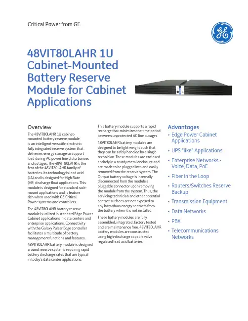
Critical Power from GEOverviewThe 48VIT80LAHR 1U cabinet-mounted battery reserve moduleis an intelligent versatile electronicfully integrated reserve system that deliveries energy storage to support load during AC power line disturbances and outages. The 48VIT80LAHR is the first of the 48VIT80LAHR family of batteries. Its technology is lead acid (LA) and is designed for High Rate (HR) discharge float applications. This module is designed for standard rack-mount applications and is featurerich when used with GE CriticalPower systems and controllers.The 48VIT80LAHR battery reserve module is utilized in standard Edge Power Cabinet applications in data centers and enterprise applications. Connectivity with the Galaxy Pulsar Edge controller facilitates a multitude of battery management functions and features.48VIT80LAHR battery module is designed around reserve systems requiring rapid battery discharge rates that are typical in today’s data center applications. This battery module supports a rapidrecharge that minimizes the time periodbetween unprotected AC line outages.48VIT80LAHR battery modules aredesigned to be light weight such thatthey can be safely handled by a singletechnician. These modules are enclosedentirely in a sturdy metal enclosure andare made to be plugged into and easilyremoved from the reserve system. TheOutput battery voltage is internallydisconnected from the module’spluggable connector upon removingthe module from the system. Thus, theservicing technician and other potentialcontact surfaces are not exposed toany hazardous energy contacts fromthe battery when it is not installed.These battery modules are fullyassembled, integrated, factory testedand are maintenance free. 48VIT80LAHRbattery modules are constructedusing high-discharge capable valveregulated lead acid batteries.Advantages• Edge Power CabinetApplications• UPS “like” Applications• Enterprise Networks -Voice, Data, PoE• Fiber in the Loop• Routers/Switches ReserveBackup• Transmission Equipment• Data Networks• PBX• TelecommunicationsNetworks48VIT80LAHR 1U Cabinet-MountedBattery Reserve Module for CabinetApplicationsKey FeaturesStandard System Features• Valve regulated design• Designed for High Rate usage• Utilizes absorbent glassmat technology• Standard 19” rack-mount 1U module • Pluggable – Easilyinstalled or removed• Designed for parallel application • Usable in vertical or horizontal mount • Keyed for polarity management • Vented for front to backair flow and exhaust• Maintenance free (Nowater topping-off)• Non-spillable• Front panel LED status indicators • Configuration rotary switchfor system identification• Approved for air transportBattery Management Features:• Integrated Low Voltage Disconnect (LVD) with autonomous disconnect/reconnect• Integrated overcurrentfuse protection • Internal electronics providetemperature and partial stringvoltage measurements• Emergency Power-Off inputFeatures With GE System Controller:• Robust RS485 systemcommunication bus compatiblewith GE controllers• Automatic communicationlink-up with GE controllers• Active recharge currentlimit (Float/Boost)• Charge and Dischargecurrent monitoring• Internal module voltage monitoring• Standard Inventory managementincluding part number, serialnumber, series number, softwareversions, date of manufacture,and date of last charge• Battery Low Voltage Disconnect (LVD)–User configurable batterydisconnect/reconnectvoltage set-points–Adaptive High Rate LVD feature• Float/boost mode control–Manual boost–Manual timed boostlocally and remotely–Auto boost terminatedby time or current• Battery discharge testing–Manual (local/remote)–Periodic–Configurable thresholdor 20% algorithm–Graphical discharge data available–Rectifiers kept on-lineduring test for backup–State of charge indication–Reserve time prediction*• Slope Thermal Compensation (STC)–High and Low temperature comp–Step temperature runaway backup–Separate Low STC Enable/Disable–Configurable mV/°C slopetemp-comp rates–High temperaturedisconnect settingPHYSICAL DIMENSIONS1.75in H, 16.5in W, 17.25in D45mm H, 419mm W, 438mm D2Galaxy 1U Battery Module | 3 | Galaxy 1U Battery Module DISCHARGE TIME END MODULE VOLTAGE 20 SEC30 SEC40 SEC50 SEC60 (1MIN)2 MIN3 MIN4 MIN43.2 V 40.8 V 39.6 V 4902458043464198381031772620230438.4 V 36.0 V 33.6 V 31.2 VDISCHARGE TIME END MODULE VOLTAGE 5 MIN 10 MIN 15 MIN 20 MIN 30 MIN 40 MIN 50 MIN 60 MIN 120 MIN43.2 V 1476100873062347336030026414640.8 V 176********66049337331027114839.6 V 1863116738.4 V 1890118483068450438231627615136.0 V 1944120084869551038732027815233.6 V 1980122285770151438932328015231.2 V19981233864705516392324280152Discharge Data: Constant Power Discharge Characteristics at 25°C (77°F) WattsPERFORMANCE SPECIFICATIONS Nominal Voltage48 Volts (24 cells)Float/Standby: 54.5 Volts nom (54.0 to 55.2 Volts)Cyclic: 57.6 to 60.0 Volts (2.4A max, float <90mA)Nominal Capacity1-Min Rate (W, V): TBD Ah5-Min Rate (1998W, 31.2V): 3.7 Ah 15-Min Rate (864W, 31.2V): 4.5 Ah 1-Hr Rate (5.80A ,35V): 5.8 Ah 10-Hr Rate (800mA, 42V): 8.0 Ah Approximate Weight 35lbs (15.9 kg)Max Discharge Current (5 Min)45 A Max Short duration Discharge Current (10 sec)80.0 A Internal Resistance (approx.)60 mΩ*Shelf Life (self-discharge)<3% per month (25°C)Operating Temperature Range Charge: 32°F (0°C) to 104°F (40°C)Discharge: -4°F (-20°C) to 122°F (50°C)Storage Temperature Range -4°F (-20°C) to104°F (40°C)Operating Relative Humidity 0 - 95% (non-condensing)Case MaterialAcid-resistant, coated, steel jacket4Galaxy 1U Battery Module | DISCHARGE TIME END MODULE VOLTAGE 5 MIN10 MIN15 MIN20 MIN30 MIN40 MIN50 MIN60 MIN120 MIN43.2 V 32.922.115.713.310.07.5 6.2 5.5 3.040.8 V 40.024.617.114.110.47.86.45.6 3.139.6 V 5.6 3.138.4 V 42.925.917.914.610.68.06.6 5.7 3.136.0 V 44.126.418.314.910.88.1 6.7 5.7 3.133.6 V 45.026.818.515.010.88.1 6.7 5.8 3.131.2 V45.427.018.615.110.98.26.75.83.1Discharge Data: Constant Power Discharge Characteristics at 25°C (77°F) AmpsCertificationsTYPE IDSafety CE UL 94-VOEMC FCC/EN55022 Class B, CISPR22 Level B ESD EN 61000-4-2 level 4IEC 61056-1JIS C 8702-1GB/T19639.1Effect of Temperature on Long Term Float Life10654321122°F10486680.5L i f e E x p e c t a n c y (y e a r )Battery TemperatureNote: Due to self-discharge, it is necessary that they be charged within 6 months of storage Permanent loss of capacity may result if this procedure is not kept.Ordering InformationORDERING CODE MODEL DESCRIPTION150********VIT80LAHR1U HR VRLA Battery Reserve Module5 | Galaxy 1U Battery ModuleNotes6Galaxy 1U Battery Module | Notes7 | Galaxy 1U Battery ModuleManagement VisibilityGalaxy Manager* software is the centralized visibility and control component of a comprehensive power management system designed to meet engineering, operations and maintenance needs. The Galaxy Manager client-server architecture enables remote access to system controllers across the power network.• Dashboard display with one-click access to management information database • Trend analysis• Scheduled or on demand reports• Fault, configuration, asset, and performance managementTrainingGE offers on-site and classroom training options based on certification curriculum. Technical training can be tailored to individual customer needs. Training enables customers and partners to more effectively manage and support the powerinfrastructure. We have built our training program on practical learning objectives that are relevant to specific technologies or infrastructure design objectives.Service & SupportGE field service and support personnel are trusted advisors to our customers – always available to answer questions and help with any project, large or small. Our certified professional services team consists of experts in every aspect of power conversion with the resources and experience to handle large turnkey projects along with custom approaches to complex challenges. Proven systems engineering and installation best practices are designed to safely deliver results that exceed our customers’ expectations.WarrantyGE is committed to providing quality products and solutions. We have developed a comprehensive warranty that protects you and provides a simple way to get your products repaired or replaced as soon as possible.For full warranty terms and conditions please go to .Reliability • • •Intelligence • • •Investment Protection • • •On Time Delivery• Standard building blocks • 4 - 6 week availability • 24/7 technical support*Registered trademark of the General Electric Company.The GE brand, logo, and lumination are trademarks of the General Electric Company. © 2016 General Electric rmation provided is subject to change without notice. All values are design or typical values when measured under laboratory conditions.CPDS-EDGE, Rev. 06/2016Critical Power from GE 601 Shiloh Road Plano, TX 75074 +1 877 546 3243。
GEFLEX GFX-M1 / GFX-S1 /GFX-E1MODULAR POWER CONTROLLER FOR TEMPERATURE CONTROLLED ZONESMain applications•Plastic extruders•Plastic injection presses •Blowers•Plastic and rubber processing machines•Wrapping machines •Packaging machines •Thermal processes with electric heating Main features•Three versions:MASTER - independent temperature control and communication unitSLAVE - independent temperature control unitEXPANSION - for three-phase loads •SSR (Solid State Relay) zero crossing •Rated voltage:480Vac rms, 50-50Hz•Rated current (AC1): 25A, 40A,60A, 75A, 90A, 120A•Protection: IP20•Installation: DIN bar and panel •Universal temperature input,accuracy 0.2%•Configurable digital input•Logic output or "cooling" relay•Load current detection with integrated CT •Heat/cool PID, selection of cooling fluid, self-tuning,auto-tuning, soft-start• 4 generic alarms, LBA and HB alarms • 2 configurable relay outputs•Field bus for Master:std: “Modbus RTU” with Serial RS485 opticallyopt: “PROFIBUS DP”, “CANopen”,“DeviceNet”PROFILEAn innovative, integrated system to con-trol power and temperature, designed for industrial electric heating processes.The system architecture is optimized for temperature control of multizone plants. It consists of a control unit, i.e., the PID microprocessor controller plus load control device (AT and VT), and a power module (SSR) with aluminum heat sink. The system is compact and easy to install and use.Models and communicationThe system has high communication capacity and interfaces without limitation with the automation environment.Three standard protocols are available: Modbus RTU, Profibus DP and CANopen implemented in the Geflex "master," which in turn communicates with up to nine Geflex "slaves" by means of an internal bus.Every Geflex can tune to the network communication speed (baud) with a self-learning sequence. In addition to connec-ting to PLCs, terminals, and PCs, the "master" is able to control a control loop. PowerFive current levels are offered: 25, 40, 60, 75, 90 and 120A, all with rated voltage of 480V, single phase.To control three-phase loads, the system uses a connection with 3 Geflex units: a "master" unit that performs the PID controland transmits (via internal bus) the powercommand to two other "expansion" unitsequipped with SSR module only.The power control has double SCR inantiparallel, zero crossing switching princi-ple, with configurable proportional cycletime.The electrical connections for power andcontrol are completely separate to increa-se electrical safety and reduce electroma-gnetic interference.MechanicsThe mechanical elements have beencarefully designed and tested for maxi-mum ease of installation and to guaranteehigh resistance to vibration and thermalstress.Diagnostic LEDsThe lower section has 3 LEDs that indica-te the operating state of the field bus, tem-perature sensor errors, and the conduc-ting state of the power unit.Temperature inputThe temperature input is universal and canbe connected to a wide variety of signaltypes: thermocouples, resistance thermo-meters, input from 4...20mA transmitters,definable only by software, without theneed for external adapter shunts.Accuracy of 0.2% guarantees excellentcontrol of the heat process.PIDThe control algorithm adapts to every typeof heat process.Up to 14 different control modes are avai-lable: from simple ON/OFF control to sin-gle or double action heat/cool PID; forcooling, simply indicate the fluid beingused.Sophisticated and efficient algorithms forautomatic tuning of control parametersprovide precise process control withoutuser intervention.Outputs and digital inputThe instrument can have up to 3 outputs:a cooling (3A, 250V) or logic (24Vdc,35mA) relay and two optional alarm relayoutputs (3A, 250V).The outputs are freely configurable viasoftware.By means of internal bus, each "slave"can activate the two relay outputs on the"master" following alarm conditions tocreate electrical clearance or block signalsset to assure safe operation of technologi-cal systems.This further reduces electromechanicalwiring.At the logic level, there are 4 genericalarms configurable as: absolute, devia-tion, direct, reverse, window, in latching ornon-latching mode, disabled at power-up.With the isolated digital input always avai-lable, you can select one of the two pre-POWER MODULEDISSIPATION CURVESCONNECTION EXAMPLESWe advise you to connect a 120Ω1/4W resistance between the "CAN_L" and "CAN_H" signals at both ends of the DeviceNet network.GEFRAN spa reserves the right to make aesthetic or functional changes at any time and without notice.GEFRAN spa via Sebina, 74 - 25050 Provaglio d’Iseo (BS)Tel.03098881 - fax 0309839063Internet: DTS_GFX_0408_ENG。
计数・计时器GE 系列使用说明书非常感谢您购买(株)韩国韩荣电子有限公司的产品。
请确认产品是否相符,并按照以下事项使用。
----------------------------------------------------------(株)韩国韩荣电子有限公司的认证现状安全注意事项为正确使用本产品,请务必在使用前认真阅读安全注意事项。
注意事项里列明的有关安全方面的重要内容,请务必遵守。
安全注意事项区分为危险、警告、注意。
危 险输出/输入端子有触电的危险,切勿与身体及通电物接触。
警 告1. 本机器的故障或异常有造成重大事故的危险,请在外围安装相应的保护回路,以防发生事故。
2. 本机器未附带电源开关及保险丝,需在外围另外安装。
(保险丝额定:250V 0.5A )3. 为了防止本机器发生破损及故障,请务必以额定电源电压供电。
4. 为了防止触电及机器故障,在未完成所有配线之前,切勿投入电源。
5. 本机器非属防爆构造,切勿在有易燃性、爆发性气体的场所使用。
6. 切勿对本机器进行分解、加工、改线、修理,会有触电、异常动作、火灾的危险。
7. 为了防止发生触电、误动作、故障,安装、拆卸本机器时,请把电源关掉。
8. 未按照制造商所指定的方法使用,可能会受伤或造成财产损失。
9. 在通电中使用本机器时,因有触电的危险,请把本机器先安装到面板上后再使用。
注 意1. 使用说明书的内容可能会在未事先通报或预告的状况下变更。
2. 请确认是否与订购的式样一致。
3. 请确认产品的在运输过程中的破损与否及异常状态。
4. 切勿在有腐蚀性气体(特别是有害气体,氨等)、易燃性气体的场所使用。
5. 请避开会直接对产品引起震动或冲击的场所使用。
6. 请在无水、油、药品、蒸汽、灰尘、盐分、铁粉等(污染等级1或2)的场所使用。
7. 切勿用酒精、苯等有机溶剂擦拭本产品(请使用中性洗剂)。
8. 请避开磁场阻碍大或会产生静电、磁场干扰的场所。
GEIndustrial SolutionsCR193 B,C,D and EVacuum Limitamp *ContactorsRenewal Parts BulletinBCS Switchgear Inc.Switchgear | Circuit Breakers | Parts | Tech Support | 888.599.0486Need Help? 888.599.0486Table of ContentsGeneral Information (3)Contactor Product Number Matrix (4)Mounting Plates, Pull Handle, Interlock Driver Pins (5)Auxiliary Interlock Wire Harnesses (5)Coil Assembly (5)Vacuum Bottle Assemblies (5)Push Off Springs and Guide Parts (6)Contactor Moving Top Assembly (6)Bottle Guide Assemblies (6)Auxiliary Interlocks (6)Stab-in Contactor Parts (7)Bottom Terminal Parts (7)Contactor Adjustment Tools (7)These instructions do not purport to cover all details or variations in equipment for every possible contingency tobe met in connection with installation, operation or maintenance. Should further information be desired or shouldparticular problems arise which are not covered sufficiently for the Purchaser’s purposes, the matter should bereferred to the nearest GE Sales office.2 CR193B, C, D and E Renewal Parts Bulletin | 888.599.0486Need Help? 888.599.0486General InformationThis renewal parts bulletin will provide the proper identification of standard parts which may be required for the maintenance of the Vacuum Limitamp contactors.Both the complete contactors and required renewal parts are shown as product numbers and are supported by photographs or drawings. Product numbers identified in this bulletin may not be the same as those parts on the original equipment. The renewal part product numbers are shown in kit form.It is the intent of this bulletin to give our customers a quick and accurate way to identify parts required for normal maintenance of the Vacuum Limitamp contactors. Unless otherwise stated, all of the parts shown in the bulletin are compatible with the contactors manufactured since 1985.Attention should be given to forecasting your particular renewal parts requirement to ensure on-site availability of the specific parts as required for normal maintenance and proper operation of your equipment. To maintain maximum operating efficiency and reliability of your equipment, genuine GE renewal parts are recommended. Since contactors are supplied to meet specific customer control and distribution requirements, certain replacement parts not listed in this publication may occasionally be required. Please refer to the factory for these requests.In these situations, please provide a complete description ofthe part, along with the complete data shown on the contactor nameplate that is affixed to the top of the contactor. For pricing and availability of parts shown in this bulletin, contact your nearest GE sales office.When replacing existing bottles, please be sure to use the new bottle with the same product number. Never intermix different vacuum bottle product numbers within the same contactor. When one bottle needs replacement, GE recommends replacing all three bottles to help maintain the most reliable system.3 | 888.599.0486Need Help? 888.599.0486CR193B, C, D and E Renewal Parts BulletinContactor Product Number Matrix++ Voltage for contactor main coil is always 110/115DC.** The sum of normally open and normally closed auxiliarycontacts must be a multiple of five (5). Each interlock blockcontains five (5 contacts). A contactor may contain a maximumof four (4) blocks, two (2) being the maximum on either side. Typical contactor number: CR193D110L01005AL• 400A contactor• w/o mechanical latch—110/115VDC main coil• 10 normally open aux. contacts• 5 normally closed aux. contacts• Stab-in style contactor• Aux. blocks mounted on left side of contactor4 CR193B, C, D and E Renewal Parts BulletinCR193B, C, D and E Renewal Parts Bulletin12345Figure 1. Contactors can be identified by their product number, located on thenameplate on the top of the contactor Note: 400A contactor shown in photo400 Amp ContactorCR193B and D Vacuum contactors are designed for equipment used in starting AC motors with line voltages from 1000-Volts to a maximum of 7200-Volts, transformer feeders, and other medium voltage control equipment.800 Amp ContactorCR193C and E Vacuum contactors are designed for equipmentused in starting AC motors with line voltages from 1000-Volts to a maximum of 7200-Volts, transformer feeders, and other mediumvoltage control equipment.Item DescriptionProduct Number Notes 1 Plug mounting bracket 55B532586P1 Four plug holes, 12 pins per plug 1 Old style bracket 55B533219G1 Three plug holes, 19 pins per plug 2 Pull handle 55A213967P1 400A contactor only 3 Slide plate (left) 55B528941G1 400A contactor only 4 Slide plate (right) 55B528942G2 400A contactor only 5 Interlock driver pin 55B533066G1 400A contactor 5Interlock driver plate55B533358P1800A contactorFigure 2.Wire Harness Assembly Figure 3. Coil Assembly with mounting boltsDescription Product Number 400A Contactor 55D781008G3R 800A Contactor55D781014G3RFigure 4. 400A Vacuum Bottle w/ adjustment nut on fixed endDescriptionProduct Number Vacuum bottle assembly55C679832G1Figure 5. 400A Vacuum Bottle w/ fixed end mounting boltDescription Product Number Double block harness VCP6 Old style plug and harnessVCP3DescriptionProduct Number Vacuum bottle assembly55C679832G25Figure 9. Bottle Guide Assembly (400A on left/ 800A on right)Description Product Number400A Contactor 55D781011G1R800A Contactor 55D781017G1RFigure 6. 800A Vacuum Bottle AssemblyDescription Product Number800A bottle assembly55C679827G1 Figure 7. Push Off Springs and Guide Parts Figure 10800A BlockThe table lists all possible combinations of auxiliary interlocks within a single block. Select the contact arrangement desired and add the suffix letter to the appropriate product number(i.e. 55C679809G2RP, block for 400A contactor with 4 NO and1 NC contacts)Description Product Number400A Contactor 55D781008G2R 800A Contactor 55D781014G2R Contactor Product Number 400A Contactor55C679809_____800A Contactor 55C679814_____ Figure 8. Contactor Moving Top AssemblySufx NO NCG1RP 5 0G2RP 4 1G3RP 3 2G4RP 2 3G5RP 1 4G6RP 0 5NO = Normally open contactsNC = Normally closed contactsInterlock Mounting PlateContactorLeft side ofContactor†Right side ofcontactor †400A Contactor 55B532537P1 55B532537P2800A Contactor 55C679815P2 55C679815P1 Description Product Number400A Contactor 55D781008G1R800A Contactor 55D781014G1R† Side of contactor when viewed from the coil side6 CR193B, C, D and E Renewal Parts BulletinCR193B, C, D and E Renewal Parts Bulletin123Figure 11. 400A Stab-In Contactor PartsItem Description Product Number QuantityNotes1 Side barrier 55C679821P3 12 Phase divider 55C679821P2 23 Line Side Stab “T” block 55B532562P3 3 Stab block thickness.500”, used prior to 2001 3Line Side Stab “T” Block55B532562P43Stab block thickness.375”, used since 2001Figure 14. 400A Load Side Stab-In Terminal w/ .375 stab blockDescription Product Number Bottom terminal55C679839P1Figure 15. 400A Load Side Terminal for Bolt-in ContactorDescription Product Number Bottom terminal55C679838P1Figure 16. Stab “T” BlocksFigure 12. 400A Load Side Stab-In Terminal w/ .500” stab block12ItemDescriptionProduct Number Notes1 Line Side Stab “T” block 55B532562P3 Stab block thickness .500” for 400A contactor2 Line Side Stab “T” Block 55B532562P4 Stab block thickness .375” for 400A contactor 3Line and Load Side Stab “T” block, 800A55B532562P5Stab block thickness .500” for 800A contactor. Not shownDescription Product Number Bottom terminal 55C679831P1 Clamp block55B532580P1 Both parts w/hardware55D781008G5RFigure 13. 400A Load Side Terminal for Bolt-In Contactor prior to 2001 Figure 17. Contactor Adjustment Tool KitDescription Product Number Bottom terminal 55C679830P1 Clamp block55B532580P1 Both parts w/hardware55D781008G4RDescription Product Number 400A Contactor 302A3900DCG1 800A Contactor302A3900DCG27GEIndustrial Solutions41 Woodford Avenue Plainville, CT 060621-800-431-7867 *Trademark of the General Electric Company and/or its subsidiaries.Information provided is subject to change without notice. Please verify all details with GE. All values are design or typical values when measured under laboratory conditions, and GE makes no warranty or guarantee, express or implied, that such performance will be obtained under end-use conditions.3.15 GEF-8016C。
GEIndustrial SolutionsElfaPlus Unibis™Saving up to 50% spacein distribution boardsbecomesEd. 022 circuits in 1 moCompact MCBs Unibis ™: the soUnibis MCBs are one of the latest introductions in the ElfaPlus range of modular devices: they are developed to reduce the size of the distribution board to the absolute minimum . Performances are up to 10kA .•Two i n d ep endan tc i r cu it si n1 m o d u l e•World-premièrePatent registeredSafety terminalsUp to 6mm 2 + 4mm 2 wires together.Brandnew design: 2P in 1 module,3 and 4P in 2 modules acc. to EN 60898 Complete range: from 3- 4.5 -6 up to 10kA (2), 2 – 40 Amps, B and C curves 100% compatible with all ElfaPlus auxiliaries and accessories100% ElfaPlus quality and reliabilitydule2P in 1 mod.1P+1P in 1 mod.1P+N in 1 mod.(1)3P in 2 mod.4P in 2 mod.4 performances up to 10kAGreen or red fl ag on toggle with isolation applicationsCorrect information about the real position. Minimum 5mm distance between open contacts is ensured.Part of the family Compact MCBs Unibis fi t perfectly in the ElfaPlus range.Safety terminals IP20 The capacity of Unibis terminals has been doubled. Connection possibilities:2 x 4mm2 or(1 x 4mm2) + (1 x 6mm2).Full functionalityA small auxiliary contact is the interface to the full functionality of auxiliaries and accessories.Easy to replaceDouble clips makes it easy to replace the MCBs, especially when a busbar is installed.High performance clipsTo fi x the MCB to theDIN rail.UserfriendlyAll screws are on the samelevel to work fast and easy.High performance torqueUp to 3Nm.Compact MCBs Unibis™:quality and reliability guaranteed The solution forEmpty DIN-RailFREE DIN-RAIL FOR EXTENSIONSDISTRIBUTION BOARD REDUCED BY 50%ORReplacing existing MCBs by compact MCBs Unibis ™IN1P+1P/1mod.OUT1P/1mod.Saving up to 50% space in distribution boards!renovationsAfterBefore12 x 2P MCBs =24 MODULES@19761 /ex/industrialsolutionsDiscover more new products6882Ref.I/2458/E/EX5.Ed.9/13©CopyrightGEIndustrialSolutions213 ElfaPlus Fixwell™Perfect connection ofMCBs and RCCBswithout toolswithin seconds!2008TeleRECThe UltimateReconnection System10’’20’0202’30’0’Easy, fast and reliableFixwell MCBs and RCCBs aredeveloped to reduce theinstallation up to 40%.Toolfree terminal connection,guaranteed reliability fromthe very first moment byplug&play.Fixwell™Ensuring power continuityTeleREC, the intelligent relaythat attempts 6 times– with varying intervals –to reclose the RCCB afteran earth leakage ora manual disconnect.TeleRECBelgiumGE Industrial BelgiumNieuwevaart 51B-9000 GentTel. +32 (0)9 265 21 11FinlandGE Industrial SolutionsKuortaneenkatu 2FI-00510 HelsinkiTel. +358 (0)10 394 3760FranceGE Industrial SolutionsParis Nord 213, rue de la PerdrixF-95958 Roissy CDG CédexTel. +33 (0)800 912 816GermanyGE Industrial SolutionsRobert-Bosch Str. 2aD-50354 Hürth-EfferenTel. +49 (0) 2233/ 9719-0HungaryGE Hungary Kft.Vaci ut 81-83.H-1139 BudapestTel. +36 1 447 6050RussiaGE Industrial Solutions27/8, Electrozavodskaya streetMoscow, 107023Tel. +7 495 937 11 11South AfricaGE Industrial SolutionsUnit 4, 130 Gazelle AvenueCorporate Park Midrand 1685P.O. Box 76672 Wendywood 2144Tel. +27 11 238 3000SpainGE Industrial SolutionsP.I. Clot del Tufau, s/nE-08295 Sant Vicenç de CastelletTel. +34 900 993 625United Arab EmiratesGE Industrial SolutionsInjaz Building, 3rd FloorDubai Internet CityPO Box 11549, DubaiTel. +971 4 4546912United KingdomGE Industrial Solutions2 The Arena, Downshire WayBracknell, Berkshire.RG12 1PUTel. +44 (0)800 587 1239ItalyGE Industrial SolutionsCentro Direzionale ColleoniVia Paracelso 16Palazzo Andromeda B1I-20864 Agrate Brianza (MB)Tel. +39 039 637 371NetherlandsGE Industrial SolutionsParallelweg 10Nl-7482 CA HaaksbergenTel. +31 (0)53 573 03 03PolandGE Power ControlsUl. Odrowaza 1503-310 WarszawaTel. +48 22 519 76 00Ul. Leszczyńska 643-300 Bielsko-BiałaTel. +48 33 828 62 33PortugalGE Industrial SolutionsRua Camilo Castelo Branco, 805Apartado 2770P-4401-601 Vila Nova de GaiaTel. +351 22 374 60 00。
GE发电设备与水处理水处理及工艺过程处理EDIEDI工业用电去离子模块相当长的一段时间,许多公司试图寻找一种操作简单、无需酸碱再生的技术来替代混床技术。
现在的EDI 技术已经实现了这个梦想。
而其中GE 的E-CELL 品牌的EDI 在全球范围占据约一半的市场份额。
目前,最新流行的纯水处理技术为:E-CELL 的EDI 采用模块化技术,通过不同数量的模块搭配,可以适应各种水处理要求。
其为发电、半导体、微电子、化工以及制药等行业的高纯水的生产提供有力保障。
EDI 系统整机EDI 利用传统的离子交换树脂将水中的污染离子去除,其最大的优点在于:EDI 技术采用直流电迫使污染离子持续的从进水中迁移出来,并穿过离子床和离子交换膜进入浓水室。
同时直流电能够将水分子电离成氢离子和氢氧根离子,持续的对树脂进行再生。
因此EDI 可以连续、可预知的生产出等同甚至优于混床出水的高纯水。
反渗透E-Cell 预处理-MF/UF EDI 相较于相较于混床混床• 工艺先进 • 无需化学品再生 • 运行成本大幅低于混床 • 连续运行连续运行,,操作简单 • 减少设备占地空间EDI 典型应用• 半导体半导体、、电子电子、、太阳能 • 化工化工、、钢铁钢铁、、冶金 • 发电发电((锅炉给水锅炉给水)) • 制药制药((高温制药用模块高温制药用模块)) • 实验室实验室((Mini 模块模块))E-Cell 模块分解图3系列典型流程图有别于GE 的2系列EDI,3系列EDI 在浓水室添加离子交换树脂。
这种专利技术发明于二十世纪六十年代,但真正的商业运用始于最近数年。
阴极板11阳离子交换膜浓水室阴离子交换膜 淡水室3系列EDI 的特点 • 浓水室添加树脂浓水室添加树脂,,电耗低 • 逆流运行逆流运行,,降低结垢倾向 • 出水水质高出水水质高,,长期运行稳定 • 无需向浓水室加盐无需向浓水室加盐和浓水循环和浓水循环和浓水循环,,简质量保证• 具有CE 、UL 和CSA 标识 • FDA 认证认证((制药用模块制药用模块)) • 由通过ISO9001:2000认证的工厂制造模块名模块名称称E -CELL CELL--3X 3X MK MK--3 尺寸 重量重量装运重量150kg92kg尺寸(宽x 高x 厚)30.5cm x 61cm x 70.5cm 30cm x 61cm x 48cm 进水 水质 要求要求总可交换阴离子(ppm 以CaCO3计) <25 <25 电导率(us/cm) <43 <43 pH 4-11 4-11 温度(°C)4.4-38 4.4-38 硬度(ppm 以CaCO3计)<1.0 <1.0 二氧化硅(ppm 以SiO2计) <1.0 <1.0 TOC(ppm) <0.5 <0.5 浊度(NTU) <1.0 <1.0 色度(APHA) 5 5 余氯(ppm) <0.05 <0.05 Fe, Mn, H2S(ppm) <0.01 <0.01 氧化剂 未检出 未检出 油脂 未检出 未检出 SDI15min<1.0 <1.0 出水 水质水质电阻率(Mohm.cm)>16 >16 pH6.5-8.06.5-8.0二氧化硅去除率 高达99%或低于5ppb 高达99%或低于5ppb 硼去除率>95% >95% 工作 参数参数标准产水量(m3/hr) 5 3.4 产水量范围(m3/hr) 2.27-6.36 1.7-4.5 极水流量设定(L/hr)80 80 回收率 87%-95% 87%-95% 电压(VDC) 0-400 0-300 电流(ADC) 0-5.2 0-5.2 进水压力(Bar)4.1-6.9 4.8-6.9 淡水进口/出口标准压降(Bar) 1.4-2.8 1.4-2.4 淡水出口/浓水进口压差(Bar)0.340.34模块名模块名称称MK MK--3 Pharm HT 3 Pharm HT MK MK--3 Mini HT Mini HT 尺寸 重量重量装运重量92kg55kg尺寸(宽x 高x 厚)30cm x 61cm x 48cm 30cm x 61cm x 27cm 进水 水质 要求要求总可交换阴离子(ppm 以CaCO3计) <25 <25 电导率(us/cm) <43 <43 pH 5-9 4-11 温度(°C)4.4-40 4.4-38 硬度(ppm 以CaCO3计)<1.0 <1.0 二氧化硅(ppm 以SiO2计) <1.0 <1.0 TOC(ppm) <0.5 <0.5 浊度(NTU) <1.0 <1.0 色度(APHA) 5 5 余氯(ppm) <0.05 <0.05 Fe, Mn, H2S(ppm) <0.01 <0.01 氧化剂 未检出 未检出 油脂 未检出 未检出 SDI15min<1.0 <1.0 出水 水质水质电阻率(Mohm.cm)>10 >10 pH6.5-8.06.5-8.0二氧化硅去除率 高达99%或低于5ppb 高达99%或低于5ppb TOC< 500 < 500 工作 参数参数标准产水量(m3/hr) 4.1 1.14 产水量范围(m3/hr) 1.6-4. 6 0.45-1.5 极水流量设定(L/hr) 80 80 回收率87%-95% 87%-95% 电压(VDC) 0-300 0-150 电流(ADC) 0-5.2 0-5.2 进水压力(Bar)4.1-6.2 4.1-6.9 淡水进口/出口标准压降(Bar) 1.4-2.4 1.4-2.4 淡水出口/浓水进口压差(Bar) 0.34 0.34 1h 高温消毒次数 160 160 消毒温度(°C)80-8580-85天津碱厂 华能济宁电厂山东宏达化工 南京金陵电厂中能硅业 成都天威除了EDI,GE 水处理还提供超滤(浸没式、压力式)、MBR、NF、RO、滤芯、ED/EDR、ZLD (零液体排放)、ABMet(含金属离子废水处理)、RO 整机、海水淡化、HERO 等产品与技术。