三层交换机配置rip路由的方法和步骤
- 格式:docx
- 大小:17.22 KB
- 文档页数:1
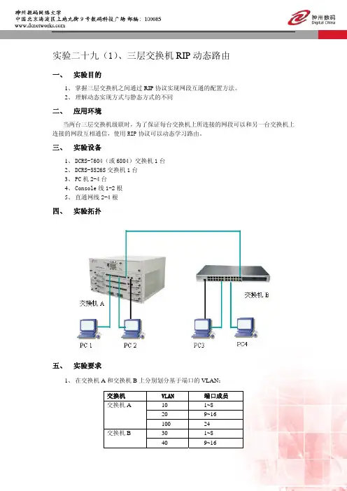
实验二十九(1)、三层交换机RIP动态路由一、 实验目的1、掌握三层交换机之间通过RIP协议实现网段互通的配置方法。
2、理解动态实现方式与静态方式的不同二、 应用环境当两台三层交换机级联时,为了保证每台交换机上所连接的网段可以和另一台交换机上连接的网段互相通信,使用RIP协议可以动态学习路由。
三、 实验设备1、DCRS-7604(或6804)交换机1台2、DCRS-5526S交换机1台3、PC机2-4台4、Console线1-2根5、直通网线2-4根四、 实验拓扑五、 实验要求1、在交换机A和交换机B上分别划分基于端口的VLAN:交换机 VLAN 端口成员交换机A10 1~820 9~16100 24交换机B30 1~840 9~16101 242、交换机A和B通过的24口级联。
3、配置交换机A和B各VLAN虚拟接口的IP地址分别如下表所示:VLAN10 VLAN20 VLAN30 VLAN40 VLAN100 VLAN101 192.168.10.1 192.168.20.1 192.168.30.1192.168.40.1192.168.100.1 192.168.100.24、PC1-PC4的网络设置为:设备 IP地址 gateway MaskPC1 192.168.10.101 192.168.10.1 255.255.255.0PC2 192.168.20.101 192.168.20.1 255.255.255.0PC3 192.168.30.101 192.168.30.1 255.255.255.0PC4 192.168.40.101 192.168.40.1 255.255.255.05、验证:z没有RIP路由协议之前:PC1与PC2,PC3与PC4可以互通。
PC1、PC2与PC3、PC4不通。
z配置RIP路由协议之后:四台PC之间都可以互通。
z若实验结果和理论相符,则本实验完成。
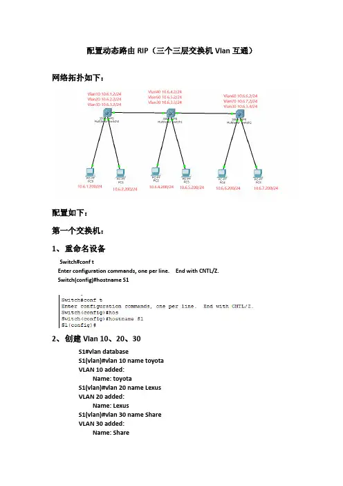
配置动态路由RIP(三个三层交换机Vlan互通)网络拓扑如下:配置如下:第一个交换机:1、重命名设备Switch#conf tEnter configuration commands, one per line. End with CNTL/Z.Switch(config)#hostname S12、创建Vlan 10、20、30S1#vlan databaseS1(vlan)#vlan 10 name toyotaVLAN 10 added:Name: toyotaS1(vlan)#vlan 20 name LexusVLAN 20 added:Name: LexusS1(vlan)#vlan 30 name ShareVLAN 30 added:Name: Share3、将网口1-5给Vlan10,网口21-24给Vlan20,将G1做扩展相互通信使用.S1(config)#interface range fastEthernet 0/1-5S1(config-if-range)#switchport access vlan 10S1(config-if-range)#exitS1(config)#interface range fastEthernet 0/21-24S1(config-if-range)#switchport access vlan 20S1(config-if-range)#exitS1(config)#interface gigabitEthernet 0/1S1(config-if)#switchport access vlan 30S1(config-if)#exit4、Vlan 配置上IPS1(config)#interface vlan 10S1(config-if)#ip address 10.6.1.2 255.255.255.0S1(config-if)#exitS1(config)#interface vlan 20S1(config-if)#ip address 10.6.2.2 255.255.255.0S1(config-if)#exitS1(config)#interface vlan 30S1(config-if)#ip address 10.6.3.2 255.255.255.0S1(config-if)#exit5、台式机测试网络,测试OKA、如发现仅能ping所属Vlan的地址,需要在三层启动IP routing6、其他二个交换机配置类似,需注意中间的S2交换机,需将G0/1、G0/2都划给Vlan30,G0/1连接S1,G0/2连接S37、配置动态路由,并查看路由状态。
H3C三层交换机和路由器的配置流程H3C三层交换机和路由器的配置流程举例讲解H3C配置三层交换机4个步骤详细用法,配置三层交换机通用的四个步骤就是:划分VLAN,并描述;给VLAN划网关;给VLAN指定端口;配置路由协议;学会这几个步骤之后就能解决所有的配置三层交换机的问题。
language-modechinese//切换到中文模式system-view//进入系统视图[H3C]displaycurrent-configuration//显示当前配置三层交换机//以下开始配置三层交换机配置三层交换机第一步:划分VLAN,并描述vlan1descriptionlocal-s3600//本交换机使用#vlan2descriptionlink-to-shanxicentre//陕西省中心#vlan3descriptionlink-to-shangjiecentre//商界分中心内部使用#vlan4descriptionlink-to-shangdongsuo//商东所#vlan5descriptionlink-to-shangnansuo//商南所配置三层交换机第二步:给VLAN划网关#interfaceVlan-interface2descriptionlinktoshanxicentreipaddress10.61.242.110255.255.255.252//省中心指定广域网关、子网掩码#interfaceVlan-interface3descriptionlinktoshangjiecentreipaddress10.161.134.65255.255.255.192//商界分中心局域网关、子网掩码#interfaceVlan-interface4descriptionlinktoshangdongsuoipaddress10.61.242.113255.255.255.252//商东所广域网关、子网掩码#interfaceVlan-interface5descriptionlinktoshangnansuoipaddress10.61.242.117255.255.255.252//商南所广域网关、子网掩码配置三层交换机第三步:给VLAN指定端口#interfaceEthernet1/0/2//将交换机的端口2指定给省中心使用descriptionlinktoshanxicentreportaccessvlan2#interfaceEthernet1/0/15-24//将交换机的端口15-24指定给分中心内部使用descriptionlinktoshangjiecentreportaccessvlan3#interfaceEthernet1/0/3//将交换机的端口3指定给商东所使用descriptionlinktoshangdongsuoportaccessvlan4#interfaceEthernet1/0/4//将交换机的端口4指定给商南所使用descriptionlinktoshangnansuoportaccessvlan5配置三层交换机第四步:配置路由协议//配静态路由(只用对远端设备配一条路由即可,本地自通)iproute0.0.0.00.0.0.010.61.242.109//指定所有网段到商东所的路由//配置三层交换机商东所的反向路由iproute10.161.134.0255.255.255.010.61.242.114iproute10.161.135.0255.255.255.010.61.242.114//配置三层交换机商南所的反向路由iproute10.161.135.0255.255.255.010.61.242.118iproute10.161.136.0255.255.255.010.61.242.118//省中心配置三层交换机:iproute10.61.242.0255.255.255.010.61.242.110//商东所242.114和商南所242.118共属的242.0指向分中心网关iproute10.161.134.0255.255.255.010.61.242.110//分中心内部网段指向分中心网关//iproute10.161.134.0255.255.255.010.61.242.110//iproute10.161.135.0255.255.255.010.61.242.110//iproute10.161.136.0255.255.255.010.61.242.110//以下开始配置路由器syslocal-user admin创建账号adminpassword simple chuntent创建密码chuntentauthorization-attribute level 3 账号权限service-type telnet打开telnet服务service-type web打开页面登陆服务telnet server enable 启用服务ip http enable 启用服务quitsysuser-interface vty 0 4authentication-mode schemequitinterface g0/0 进入外网接口配置外网ip和子网掩码ip address X.X.X.X 255.255.255.X这里地址按照您的公网ip地址和掩码填写nat outboundquitinterface vlan 1 进入内网接口配置内网ip和子网掩码ip address X.X.X.X 255.255.255.Xquitip route-static 0.0.0.0 0.0.0.0 X.X.X.X这里填写外网网关地址。

三层交换机配置rip路由的方法和步骤
本文整理于网络,仅供阅读参考
三层交换机配置rip路由的方法和步骤
三层交换机配置rip路由的方法和步骤如下建立建立packet tracer拓扑图
在三层交换机上划分vlan10和vlan20,其中vlan10用于连接校园网主机,vlan20用于连接r1
路由器之间通过v.35电缆通过串口连接,dce端连接在r1上,配置其时钟频率64000。
主机和交换机通过直连线,主机与路由器通过交叉线连接。
在s3560上配置ripv2路由协议。
在路由器r1、r2上配置ripv2路由协议。
将pc1、pc2主机默认网关设置为与直连网路设备接口ip地址。
pc1
ip: 192.168.1.2
submask: 255.255.255.0
gateway: 192.168.1.1
pc2
ip: 192.168.2.2
submask: 255.255.255.0
gateway: 192.168.2.1
验证pc1、pc2主机之间可以互相同信;。
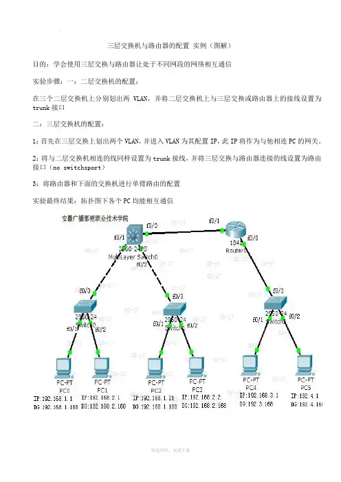
三层交换机与路由器的配置实例(图解)目的:学会使用三层交换与路由器让处于不同网段的网络相互通信实验步骤:一:二层交换机的配置:在三个二层交换机上分别划出两VLAN,并将二层交换机上与三层交换或路由器上的接线设置为trunk接口二:三层交换机的配置:1:首先在三层交换上划出两个VLAN,并进入VLAN为其配置IP,此IP将作为与他相连PC的网关。
2:将与二层交换机相连的线同样设置为trunk接线,并将三层交换与路由器连接的线设置为路由接口(no switchsport)3:将路由器和下面的交换机进行单臂路由的配置实验最终结果:拓扑图下各个PC均能相互通信交换机的配置命令:SW 0:Switch>Switch>enSwitch#confConfiguring from terminal, memory, or network [terminal]?Enter configuration commands, one per line. End with CNTL/Z.Switch(config)#vlan 2Switch(config-vlan)#exitSwitch(config)#int f0/2Switch(config-if)#switchport access vlan 2Switch(config-if)#no shutSwitch(config-if)#int f0/3Switch(config-if)#switchport mode trunk%LINEPROTO-5-UPDOWN: Line protocol on Interface FastEthernet0/3, changed state to down %LINEPROTO-5-UPDOWN: Line protocol on Interface FastEthernet0/3, changed state to up Switch(config-if)#exitSwitch(config)#SW 1:Switch>enSwitch#confConfiguring from terminal, memory, or network [terminal]?Enter configuration commands, one per line. End with CNTL/Z.Switch(config)#int f0/2Switch(config-if)#switchport access vlan 2% Access VLAN does not exist. Creating vlan 2Switch(config-if)#no shutSwitch(config-if)#exitSwitch(config)#int f0/3Switch(config-if)#switchport mode trunk%LINEPROTO-5-UPDOWN: Line protocol on Interface FastEthernet0/3, changed state to down %LINEPROTO-5-UPDOWN: Line protocol on Interface FastEthernet0/3, changed state to up Switch(config-if)#SW 2:Switch>enSwitch#confConfiguring from terminal, memory, or network [terminal]?Enter configuration commands, one per line. End with CNTL/Z.Switch(config)#int f0/2Switch(config-if)#switchport access vlan 2% Access VLAN does not exist. Creating vlan 2Switch(config-if)#exitSwitch(config)#int f0/3Switch(config-if)#switchport mode trunkSwitch(config-if)#三层交换的配置命令:Switch>enSwitch#confConfiguring from terminal, memory, or network [terminal]?Enter configuration commands, one per line. End with CNTL/Z.Switch(config)#int f0/1Switch(config-if)#switchport mode trunk%LINEPROTO-5-UPDOWN: Line protocol on Interface FastEthernet0/2, changed state to down Switch(config-if)#exitSwitch(config)#int f0/2Switch(config-if)#switchport mode trunkSwitch(config-if)#exitSwitch(config)#vlan 2Switch(config-vlan)#exitSwitch(config)#int vlan 1Switch(config-if)#no shut%LINK-5-CHANGED: Interface Vlan1, changed state to up%LINEPROTO-5-UPDOWN: Line protocol on Interface Vlan1, changed state to upSwitch(config-if)#ip address 192.168.1.168 255.255.255.0Switch(config-if)#exitSwitch(config)#int vlan 2%LINK-5-CHANGED: Interface Vlan2, changed state to up%LINEPROTO-5-UPDOWN: Line protocol on Interface Vlan2, changed state to upSwitch(config-if)#ip addSwitch(config-if)#ip address 192.168.2.168 255.255.255.0Switch(config-if)#%LINK-5-CHANGED: Interface FastEthernet0/3, changed state to up%LINEPROTO-5-UPDOWN: Line protocol on Interface FastEthernet0/3, changed state to up Switch(config-if)#exitSwitch(config)#int f0/3Switch(config-if)#no switchport%LINEPROTO-5-UPDOWN: Line protocol on Interface FastEthernet0/3, changed state to down %LINEPROTO-5-UPDOWN: Line protocol on Interface FastEthernet0/3, changed state to upSwitch(config-if)#Switch(config-if)#ip address 192.168.10.1 255.255.255.0Switch(config-if)#no shutSwitch(config-if)#exitSwitch(config)#ip routingSwitch(config-if)#exitSwitch(config)#ip route 0.0.0.0 0.0.0.0 192.168.10.2Switch(config)#路由器的配置:Router>enRouter#confConfiguring from terminal, memory, or network [terminal]?Enter configuration commands, one per line. End with CNTL/Z.Router(config)#int f0/0Router(config-if)#no shut%LINK-5-CHANGED: Interface FastEthernet0/0, changed state to upRouter(config-if)#exitRouter(config)#int f0/1Router(config-if)#no shut%LINK-5-CHANGED: Interface FastEthernet0/1, changed state to up%LINEPROTO-5-UPDOWN: Line protocol on Interface FastEthernet0/1, changed state to up Router(config-if)#exitRouter(config)#int f0/0Router(config-if)#no shutRouter(config-if)#exitRouter(config)#int f0/0.1Router(config-subif)#encapsulation dot1Q 1Router(config-subif)#ip address 192.168.3.168 255.255.255.0Router(config-subif)#exitRouter(config)#int f0/0.2Router(config-subif)#encapsulation dot1Q 2Router(config-subif)#ip addRouter(config-subif)#ip address 192.168.4.168 255.255.255.0Router(config-subif)#exitRouter(config)#ip route 0.0.0.0 0.0.0.0 192.168.10.1Router(config)#exit%SYS-5-CONFIG_I: Configured from console by consoleRouter#confConfiguring from terminal, memory, or network [terminal]? Enter configuration commands, one per line. End with CNTL/Z. Router(config)#int f0/1Router(config-if)#ip addRouter(config-if)#ip address 192.168.10.2 255.255.255.0 Router(config-if)#Welcome !!! 欢迎您的下载,资料仅供参考!。
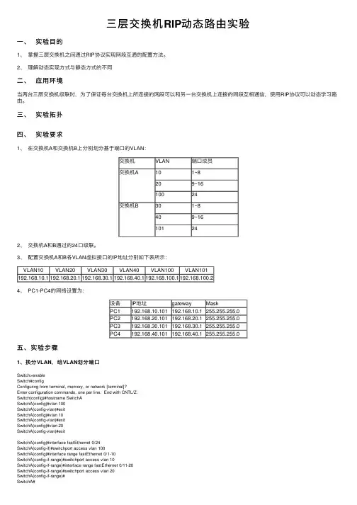
三层交换机RIP动态路由实验⼀、实验⽬的1、掌握三层交换机之间通过RIP协议实现⽹段互通的配置⽅法。
2、理解动态实现⽅式与静态⽅式的不同⼆、应⽤环境当两台三层交换机级联时,为了保证每台交换机上所连接的⽹段可以和另⼀台交换机上连接的⽹段互相通信,使⽤RIP协议可以动态学习路由。
三、实验拓扑四、实验要求1、在交换机A和交换机B上分别划分基于端⼝的VLAN:交换机VLAN 端⼝成员交换机A101~8209~1610024交换机B301~8409~16101242、交换机A和B通过的24⼝级联。
3、配置交换机A和B各VLAN虚拟接⼝的IP地址分别如下表所⽰:VLAN10VLAN20VLAN30VLAN40VLAN100VLAN101192.168.10.1192.168.20.1192.168.30.1192.168.40.1192.168.100.1192.168.100.24、 PC1-PC4的⽹络设置为:设备IP地址gateway MaskPC1 192.168.10.101192.168.10.1255.255.255.0PC2 192.168.20.101192.168.20.1255.255.255.0PC3192.168.30.101192.168.30.1255.255.255.0PC4 192.168.40.101 192.168.40.1255.255.255.0五、实验步骤1、换分VLAN,给VLAN划分端⼝Switch>enableSwitch#configConfiguring from terminal, memory, or network [terminal]?Enter configuration commands, one per line. End with CNTL/Z.Switch(config)#hostname SwitchASwitchA(config)#vlan 100SwitchA(config-vlan)#exitSwitchA(config)#vlan 10SwitchA(config-vlan)#exitSwitchA(config)#vlan 20SwitchA(config-vlan)#exitSwitchA(config)#interface fastEthernet 0/24SwitchA(config-if)#switchport access vlan 100SwitchA(config)#interface range fastEthernet 0/1-10SwitchA(config-if-range)#switchport access vlan 10SwitchA(config-if-range)#interface range fastEthernet 0/11-20SwitchA(config-if-range)#switchport access vlan 20SwitchA(config-if-range)#SwitchA# 2、给划分的VLAN设置IP SwitchA(config)#interface vlan 100SwitchA(config-if)#ip address 192.168.100.1 255.255.255.0 SwitchA(config-if)#no shutdownSwitchA(config-if)#interface vlan 10SwitchA(config-if)#ip address 192.168.10.1 255.255.255.0 SwitchA(config-if)#no shutdownSwitchA(config-if)#interface vlan 20SwitchA(config-if)#ip address 192.168.20.1 255.255.255.0 SwitchA(config-if)#no shutdownSwitchA(config-if)#exit3、设置rip动态路由(本路由直达的⽹络地址)SwitchA(config)#ip routingSwitchA(config)#router ripSwitchA(config-router)#network 192.168.10.0SwitchA(config-router)#network 192.168.20.0SwitchA(config-router)#network 192.168.100.0 在特权模式下查看路由表ps:另⼀台交换机的配置与此相似。

《计算机网络》课程设计报告题目:三层交换机的RIP动态路由配置学院:商学院专业:信息管理与信息系统班级:信息101学号:*************名:***指导教师:***完成日期:2013-7-11目录设计任务概述 (3)系统分析 (4)总体设计 (6)详细设计 (7)根据拓扑连接线路 (7)设置PC机(以PC1为例) (7)划分交换机的vlan (8)配置交换机各vlan虚接口的IP地址 (10)检验个PC机间能否通信(以PC1为例) (13)启动RIP协议实现两个交换机之间的通信 (13)启动RIP协议之后各PC机之间的通信情况 (14)设计总结 (15)参考资料 (16)设计任务概述三层交换机的RIP动态路由配置目的:理解RIP协议,掌握三层交换机RIP动态路由的配置方法。
提示路由信息协议(RIP)协议是一种动态路由选择,它基于距离矢量算法(D-V),总是按最短的路由做出相同的选择。
这种协议的网络设备只关心自己周围的世界,只与自己相邻的路由器交换信息,范围限制在15跳(15度)之内,再远,它就不关心了。
RIP应用于OSI网络七层模型的网络层。
RIP动态路由协议是典型的距离矢量路由协议,交换机开启了RIP路由协议后,会对外发送RIP的广播报文,报文信息来自本地路由表,只有当对方设备也开启了RIP路由协议,两台设备才能相互学习,知道对方连接了什么网络,从而更新自身的路由表,实现信息的寻址和转发功能。
要求:使用RIP动态路由使不同网段的计算机能相互通信。
内容:添加四台计算机,分别更改标签为PC1至PC4;添加两台三层交换机3560,分别更改标签名为SA和SB;SA和SB上分别划分3个VLAN,划分情况如下表所示:交换机名VLAN编号端口范围IP地址SA 6 1--8 172.16.6.1/247 9--16 172.16.7.1/24100 24 172.16.100.1/24 SB 8 1--8 172.16.8.1/249 9--16 172.16.9.1/24100 24 172.16.100.1/24 根据拓扑图所示,交换机之间通过F0/24口相连,PC1、PC2分别连接SA的VLAN6端口和VLAN7端口,PC3、PC4分别连接SB的VLAN8和VLAN9端口,并根据拓扑图所示配置所有计算机的IP地址,子网掩码和网关;在两台交换机上配置RIP动态路由实现全网互通。
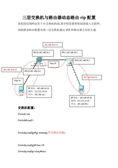
三层交换机与路由器动态路由rip配置某校园局域网由若干台交换机构成,现学校需要将校园园接入互联网,请做静态路由配置实现三层交换机通过SVI和路由器之间的互通.F0/20:192.168.20.1 F0/1:192.168.20.2F0/0:192.168.30.1Valn 20F0/10:192.168.10.1192.168.30.0/24 Valn 10IP地址:192.168.10.10掩码:255.255.255.0Switch>enSwitch#conf tSwitch(config)#ip routing(开启路由功能)Switch(config)#vlan 10Switch(config-vlan)#exitSwitch(config)#vlan 20Switch(config-vlan)#exitSwitch(config)#int f0/10(将端口分配给VLAN)Switch(config-if)#sw acc vlan 10Switch(config-if)#exitSwitch(config)#int f0/20(将端口分配给VLAN)Switch(config-if)#sw acc vlan 20Switch(config-if)#exit(配置三层交换机端口的路由功能)Switch(config)#int vlan 10Switch(config-if)#ip add 192.168.10.1 255.255.255.0 Switch(config-if)#no shutdownSwitch(config-if)#exitSwitch(config)#int vlan 20Switch(config-if)#ip add 192.168.20.1 255.255.255.0 Switch(config-if)#no shutdownSwitch(config-if)#exitSwitch(config)#router rip(配置动态路由rip协议) Switch(config-router)#network 192.168.10.0 Switch(config-router)#network 192.168.20.0 Switch(config-router)#end路由器配置:Router>enRouter#conf tRouter(config)#int f0/0(给端口分配IP地址)Router(config-if)#ip add 192.168.30.1 255.255.255.0 Router(config-if)#no shutdownRouter(config-if)#exitRouter(config-if)#int f0/1(给端口分配IP地址)Router(config-if)#ip add 192.168.20.2 255.255.255.0 Router(config-if)#no shutdownRouter(config-if)#exitSwitch(config)#router ripSwitch(config-router)#network 192.168.20.0Switch(config-router)#network 192.168.30.0 Switch(config-router)#end。
实验十八 三层交换机RIP动态路由(1)一、实验目的1.掌握三层交换机之间通过RIP协议实验网段互通的配置方法2.理解动态实验方式与静态方式的不同二、应用环境当两台三层交换机级联时,为了保证每台交换机上所连接的网段可以和另一台交换机上连接的网段互相通信,使用RIP协议可以动态学习路由。
三、实验设备及材料1.DCRS-7604交换机1台2.DCRS-5526交换机1台3.PC机2-4台4.Console线2根5.直通网线若干四、实验拓扑图五、实验内容与要求1.按照网络拓扑图连接网络;2.在交换机A、B(DCS-3926S)上划分两个基于端口的Vlan:Vlan 10和Vlan 20;交换机 Vlan 端口成员10 1/1-620 1/7-12A(DCRS-7604)100 2430 0/0/1-6B(DCRS-5526)40 0/0/7-12101 243.交换机A和B通过24口级联;4.配置交换机A和B的各Vlan虚拟接口的IP地址如下表所示:交换机 Vlan IP地址25410 192.168.10.20 192.168.20.254A(DCRS-7604)1100 192.168.100.25430 192.168.30.B(DCRS-5526)40 192.168.40.254101 192.168.100.25.PC1-PC4的网络设置为:机器 IP地址 GateWay MaskPC1 192.168.10.101 192.168.10.254 255.255.255.0254 255.255.255.0 PC2 192.168.20.101 192.168.20.254 255.255.255.0 PC3 192.168.30.101 192.168.30.254 255.255.255.0 PC4 192.168.40.101 192.168.40.6.验证配置结果:● 没有启用RIP路由协议之前PC1与PC2,PC3与PC4可以互通;PC1、PC2与PC3、PC4不通。
三层交换机与路由器的配置实例(图解)本文档旨在提供关于如何配置三层交换机与路由器的详细指南,并附有具体实例和图解。
下面将按照章节细化介绍。
1.交换机与路由器的基本概念及作用
1.1 交换机的作用与工作原理
1.2 路由器的作用与工作原理
2.三层交换机与路由器的区别与联系
2.1 三层交换机的特点和应用场景
2.2 路由器的特点和应用场景
3.三层交换机与路由器的配置前准备
3.1 设备检查与准备
3.2 网络规划与拓扑设计
4.三层交换机的配置步骤
4.1 连接与登录交换机
4.2 设置管理IP地质
4.3 配置VLAN
4.4 配置三层交换机的IP路由功能
5.路由器的配置步骤
5.1 连接与登录路由器
5.2 设置管理IP地质
5.3 配置静态路由
5.4 配置动态路由协议
6.三层交换机与路由器的互通配置
6.1 网络互通的基本原理
6.2 配置路由器与交换机之间的互联
6.3 配置路由器与其他网络设备的互联
7.实际案例分析与图解
7.1 案例一:简单局域网互通配置
7.2 案例二:跨网段通信配置
7.3 案例三:路由器的互联配置
附件:
本文档不涉及附件内容。
法律名词及注释:
1.三层交换机:三层交换机(Layer 3 Switch)是一种将交换机和路由器两者功能集成在一起的网络设备。
它具备交换机的高速交换与路由器的一些路由功能。
2.路由器:路由器(Router)是用于将数据包在互联网络中转发的网络设备。
它根据目的地IP地质来决定下一跳的路径,实现网络间的通信。
局域网内三层交换机怎么设置路由连接的方法局域网内的三层交换机确实具有一定的“路由”功能,它可以实现不同的子网连接功能,但是特别注意的问题是,它的路由功能相对路由器来说还是要弱许多的,而且三层交换机只能使用一个网络。
下面是店铺为大家整理的关于局域网内三层交换机怎么设置路由连接的方法,一起来看看吧!局域网内三层交换机怎么设置路由连接的方法通常只是局域网子网之间的互联,并不能把局域网与广域网,或者互联网连接起来,因为三层交换机所支持的路由协议非常有限,毕竟这不是它的主要功能。
我们知道,在局域网上,二层的交换机通过源MAC 地址来标识数据包的发送者,根据目的MAC 地址来转发数据包。
对于一个目的地址不在本局域网上的数据包,二层交换机不可能直接把它送到目的地,需要通过路由设备(比如传统的路由器)来转发,这时就要把交换机连接到路由设备上。
如果把交换机的缺省网关设置为路由设备的IP 地址,交换机会把需要经过路由转发的包送到路由设备上。
路由设备检查数据包的目的地址和自己的路由表,如果在路由表中找到转发路径,路由设备把该数据包转发到其它的网段上,否则,丢弃该数据包。
专用路由器昂贵、复杂、速度慢、易成为网络瓶颈,因为它要分析所有的广播包并转发其中的一部分,还要和其它的路由器交换路由信息,而且这些处理过程都是由CPU 来处理的(不是专用的ASIC )。
第三层交换机既能像二层交换机那样通过MAC 地址来标识转发数据包,也能像传统路由器那样在两个网段之间进行路由转发。
传统路由器采用软件来维护路由表,而三层交换机是通过专用的ASIC芯片来处理路由转发的。
与传统路由器相比,第三层交换机的路由速度一般要快十倍或数十倍。
大家都知道,路由器可以连接企业局域网和广域网(如因特网),但却忽略了一路由器的另一个应用,那就是它的局域网连接功能。
路由器的广域网连接可参见拓扑图图和三层交换机的路由连接图。
路由器的作用因不同的路由器类型而定,我们常说的路由器通常是指边界路由器,就是位于不同类型网络的边界,如拓扑图图和三层交换机的路由连接图所示。
三层交换配置及RIP动态路由三层交换vlan间通信1.1 问题VLAN实现了⼴播域的隔离,同时也将VLAN间的通信隔离了。
三层交换技术使得VLAN间可以通信。
通过三层交换实现VLAN间通信1.2 ⽅案为了解决了传统路由器低速、复杂所造成的⽹络瓶颈问题,引⼊了三层交换技术。
它根据实际应⽤时的情况,灵活地在⽹络第⼆层或者第三层进⾏⽹络分段。
具有三层交换功能的设备是⼀个带有第三层路由功能的第⼆层交换机。
简单地说,三层交换技术就是:⼆层交换技术+三层转发技术。
三层交换实现的拓扑如图-1所⽰:图-11.3 步骤实现此案例需要按照如下步骤进⾏。
步骤⼀:在连接PC的交换机上划分3个VLAN,并按图-1把PC机加⼊相应VLAN1. tarenasw-3L (config)#vlan 2 //vlan1是默认VLAN,不需创建2. tarenasw-3L (config-vlan)#vlan 33. tarenasw-3L (config-vlan)#exit4. tarenasw-3L (config)#interface f0/15. tarenasw-3L (config-if)#switchport mode access6. tarenasw-3L (config-if)#switchport access vlan 17. tarenasw-3L (config-if)#interface f0/28. tarenasw-3L (config-if)#switchport mode access9. tarenasw-3L (config-if)#switchport access vlan 210. tarenasw-3L (config-if)#interface f0/311. tarenasw-3L (config-if)#switchport mode access12. tarenasw-3L (config-if)#switchport access vlan 3步骤⼆:查看划分完的VLAN信息VLAN1是默认VLAN,不需单独创建,也不能改名。
三层交换机接路由器配置方法三层交换机接路由器配置方法1. 引言在网络架构中,三层交换机和路由器是两个重要的设备。
它们的协同工作可以实现有效的网络互联和数据转发。
本文将详细说明三层交换机与路由器的接口配置方法,以便读者在实际操作中能够正确配置并调试这两种设备之间的连接。
2. 背景知识在进行三层交换机和路由器的配置前,我们需要了解以下几个重要概念:•三层交换机:三层交换机是一种能够同时支持二层和三层转发的网络设备。
它具有更强大的数据处理和转发能力,可以实现更灵活的网络分段和路由控制。
•路由器:路由器是一种网络设备,主要用于连接不同的网络,并在它们之间进行数据的转发和路由控制。
路由器通常工作在网络的第三层,也就是网络层。
3. 三层交换机与路由器的连接硬件连接首先,确保三层交换机和路由器之间的物理连接正常。
一般情况下,我们需要将交换机的一个接口与路由器的一个接口通过网线连接起来。
这个连接方式可以是直连,也可以通过其他设备(如防火墙)进行中转。
VLAN配置如果需要将多个VLAN通过三层交换机连接到路由器上,我们可以通过以下步骤进行配置:1.在交换机上创建所需的VLAN,并为每个VLAN分配一个唯一的VLAN ID。
2.将各个交换机端口绑定到所对应的VLAN上。
3.配置交换机的Trunk端口,使其能够将多个VLAN的数据通过一个物理端口传输给路由器。
三层交换机接口配置在将交换机与路由器连接之前,我们需要在交换机上配置交换机接口的IP地址,并开启接口的三层功能。
具体步骤如下:1.进入交换机的命令行界面,切换到特定接口的配置模式。
2.配置接口的IP地址和子网掩码。
3.开启接口的三层功能。
路由器接口配置在将路由器与交换机连接之前,我们需要在路由器上配置路由器接口的IP地址,以及与交换机连接的网络的路由控制。
具体步骤如下:1.进入路由器的命令行界面,切换到特定接口的配置模式。
2.配置接口的IP地址和子网掩码。
3.配置路由控制,使路由器能够转发数据到与交换机连接的网络。
华为华三三层交换机配置展开全文华为三层交换机配置方法(1)本文以华为华三通信的H3C S3600-28P-SI为例,配置前首先要确定型号后缀是SI还是EI,EI的支持所有协议,SI的不支持OSPS动态协议,因此SI配置路由时可以使用静态协议和RIP协议,具体配置如下:<H3C>system-view //进入系统视图[H3C]display current-configuration //显示当前配置//以下开始配置//第一步:划分VLAN,并描述vlan 1description local-S3600vlan 2description link-to-wenquanvlan 3description link-to-ruzhouvlan 4description link-to-xiaotunvlan 5description link-to-baofengvlan 6description link-to-pingxivlan 7description link-to-pingnanvlan 8description Uplink-to-Putianvlan 9description link-to-pingxicentre//第二步:给VLAN 划网关interface Vlan-interface2description link to wenquanip address 10.41.77.41 255.255.255.192 interface Vlan-interface3description link to ruzhouip address 10.41.77.105 255.255.255.192 interface Vlan-interface4description link to xiaotunip address 10.41.77.169 255.255.255.192 interface Vlan-interface5description link to baofengip address 10.41.77.233 255.255.255.192 interface Vlan-interface6description link to pingxiip address 10.41.78.41 255.255.255.192 interface Vlan-interface7description link to pingnanip address 10.41.78.105 255.255.255.192 interface Vlan-interface8description uplink to putianip address 10.41.244.102 255.255.255.252 interface Vlan-interface9description link to pingxicentreip address 10.41.80.233 255.255.255.192 //第三步:给VLAN 指定端口interface Ethernet1/0/2description link to wenquanport access vlan 2interface Ethernet1/0/3description link to ruzhouport access vlan 3interface Ethernet1/0/4description link to xiaotunport access vlan 4interface Ethernet1/0/5description link to baofengport access vlan 5interface Ethernet1/0/6description link to pingxiport access vlan 6interface Ethernet1/0/7description link to pingnanport access vlan 7interface Ethernet1/0/8description uplink to putianport access vlan 8interface Ethernet1/0/9 to Ethernet1/0/24 description link to pingxicentreport access vlan 9//第四步:配置路由协议//(1)用RIP配动态路由ripnetwork 10.41.77.41network 10.41.77.105network 10.41.77.169network 10.41.77.233network 10.41.78.41network 10.41.78.105network 10.41.80.233network 10.41.244.102//(2)配静态路由(只用对远华为三层交换机配置命令分类:默认栏目2007.6.2 07:28 作者:weiwei2501 | 评论:1 | 阅读:0Enable //进入私有模式Configure terminal //进入全局模式service password-encryption //对密码进行加密hostname Catalyst 3550-12T1 //给三层交换机定义名称enable password 123456. //enable密码Enable secret 654321 //enable的加密密码(应该是乱码而不是654321这样)Ip subnet-zero //允许使用全0子网(默认都是打开的)Ip name-server 172.16.8.1 172.16.8.2 //三层交换机名字Catalyst 3550-12T1对应的IP地址是172.16.8.1Service dhcp //提供DHCP服务ip routing //启用三层交换机上的路由模块ExitVtp mode server //定义VTP工作模式为sever模式Vtp domain centervtp //定义VTP域的名称为centervtpVlan 2 name vlan2 //定义vlan并给vlan取名(如果不取名的话,vlan2的名字应该是vlan002)Vlan 3 name vlan3Vlan 4 name vlan4Vlan 5 name vlan5Vlan 6 name vlan6Vlan 7 name vlan7Vlan 8 name vlan8Vlan 9 name vlan9Exitinterface Port-channel 1 //进入虚拟的以太通道组1Interface gigabitethernet 0/1 //进入模块0上的吉比特以太口1 channel-group 1 mode on //把这个接口放到快速以太通道组1中Interface gigabitethernet 0/2 //同上channel-group 1 mode onport-channel load-balance src-dst-ip //定义快速以太通道组的负载均衡方式(依靠源和目的IP的方式)interface gigabitethernet 0/3 //进入模块0上的吉比特以太口3interface gigabitethernet 0/4 //同上interface gigbitethernet 0/5 //同上interface gigbitethernet 0/6 //同上interface gigbitethernet 0/7 //进入模块0上的吉比特以太口7 no shutdownspanning-tree vlan 6-9 cost 1000 //在生成树中,vlan6-9的开销定义为10000interface range gigabitethernet 0/8 – 10 //进入模块0上的吉比特以太口8,9,10no shutdownspanning-tree portfast //在这些接口上使用portfast(使用portfast以后,在生成树的时候不参加运算,直接成为转发状态)interface gigabitethernet 0/11 //进入模块0上的吉比特以太口11interface gigabitethernet 0/12 //同上interface vlan 1 //进入vlan1的逻辑接口(不是物理接口,用来给vlan做路由用)ip address 172.16.1.7 255.255.255.0 //配置IP地址和子网掩码no shutdownstandby 1 ip 172.16.1.9 //开启了冗余热备份(HSRP),冗余热备份组1,虚拟路由器的IP地址为172.16.1.9standby 1 priority 110 preempt //定义这个三层交换机在冗余热备份组1中的优先级为110,preempt是用来开启抢占模式interface vlan 2 //同上ip address 172.16.2.252 255.255.255.0no shutdownstandby 2 ip 172.16.2.254standby 2 priority 110 preemptip access-group 101 in //在入方向上使用扩展的访问控制列表101interface vlan 3 //同上ip address 172.16.3.252 255.255.255.0no shutdownstandby 3 ip 172.16.3.254standby 3 priority 110 preemptip access-group 101 ininterface vlan 4 //同上ip address 172.16.4.252 255.255.255.0no shutdownstandby 4 ip 172.16.4.254standby 4 priority 110 preemptip access-group 101 ininterface vlan 5ip address 172.16.5.252 255.255.255.0 no shutdownstandby 5 ip 172.16.5.254standby 5 priority 110 preemptip access-group 101 ininterface vlan 6ip address 172.16.6.252 255.255.255.0 no shutdownstandby 6 ip 172.16.6.254standby 6 priority 100 preemptinterface vlan 7ip address 172.16.7.252 255.255.255.0 no shutdownstandby 7 ip 172.16.7.254standby 7 priority 100 preemptinterface vlan 8ip address 172.16.8.252 255.255.255.0 no shutdownstandby 8 ip 172.16.8.254standby 8 priority 100 preemptinterface vlan 9ip address 172.16.9.252 255.255.255.0 no shutdownstandby 9 ip 172.16.9.254standby 9 priority 100 preemptaccess-list 101 deny ip any 172.16.7.0 0.0.0.255 //扩展的访问控制列表101access-list 101 permit ip any anyInterface vlan 1 //进入vlan1这个逻辑接口Ip helper-address 172.16.8.1 //可以转发广播(helper-address的作用就是把广播转化为单播,然后发向172.16.8.1)Interface vlan 2Ip helper-address 172.16.8.1Interface vlan 3ip helper-address 172.16.8.1interface vlan 4ip helper-address 172.16.8.1interface vlan 5ip helper-address 172.16.8.1interface vlan 6ip helper-address 172.16.8.1interface vlan 7ip helper-address 172.16.8.1interface vlan 9ip helper-address 172.16.8.1router rip //启用路由协议RIPversion 2 //使用的是RIPv2,如果没有这句,则是使用RIPv1network 172.16.0.0 //宣告直连的网段exitip route 0.0.0.0 0.0.0.0 172.16.9.250 //缺省路由,所有在路由表中没有办法匹配的数据包,都发向下一跳地址为172.16.9.250这个路由器line con 0line aux 0line vty 0 15 //telnet线路(路由器只有5个,是0-4)password 12345678 //login密码loginendcopy running-config startup-config 保存配置cisco 3550Switch# configure terminalSwitch(config)#vtp mode transparentSwitch(config)#vlan 10Switch(config-vlan)# name vlan10Switch(config)#exitSwitch(config)#vlan 11Switch(config-vlan)name vlan11Switch(config-vlan)endSwitch#configure terminalSwitch(config)#interface fastethernet0/9Switch(config-if)#switchport mode accessSwitch(config-if)#switchport access vlan 10Switch(config-if)#exitSwitch(config)#interface fastethernet0/10Switch(config-if)#switchport mode accessSwitch(config-if)#switchport access vlan 10Switch(config-if)#exitSwitch(config)#interface fastethernet0/11Switch(config-if)#switchport mode accessSwitch(config-if)#switchport access vlan 11Switch(config-if)#exitSwitch(config)#interface fastethernet0/12Switch(config-if)#switchport mode accessSwitch(config-if)#switchport access vlan 11Switch(config-if)#exitSwitch(config)#interface vlan10Switch(config-if)#ip address 192.168.0.1 255.255.255.0Switch(config-if)#no shutdownSwitch(config-if)#exitSwitch(config)#interface vlan11Switch(config-if)#ip address 192.168.1.1 255.255.255.0Switch(config-if)#no shutdownSwitch(config-if)#exitSwitch(config)#ip routingSwitch(config)#ip forward-protocol udpSwitch(config)#inter vlan 10ip helper 172.16.11.255 //这个命令又是什么意思?是不是转发整个网段的UDP协议?为什么用到了172.16.11.255这个地址?Switch(config)#exitSwitch(config)#inter vlan 11Switch(config-if)#ip helper 172.16.10.255 //同上?Switch(config-if)#exitSwitch(config)#ip route 0.0.0.0 0.0.0.0 Vlan10Switch(config)#ip route 0.0.0.0 0.0.0.0 Vlan11Switch(config)#conf tSwitch(config)#access-list 103 permit ip 172.16.11.00.0.0.255 172.16.10.0 0.0.0.255Switch(config)#access-list 103 permit udp any any eq bootpc Switch(config)#access-list 103 permit udp any any eq tftpSwitch(config)#access-list 103 permit udp any eq bootpc any Switch(config)#access-list 103 permit udp any eq tftp anySwitch(config)#inter vlan 10Switch(config-if)#ip directed-broadcast 103 //请解释一下这个的具体含义,本人不是太明白,懂一点意思(直接广播这个列表?是不是)Switch(config-if)#exitSwitch(config)#access-list 104 permit ip 172.16.10.0 0.0.0.255 172.16.11.0 0.0.0.255Switch(config)#access-list 104 permit udp any any eq bootpc Switch(config)#access-list 104 permit udp any any eq tftpSwitch(config)#access-list 104 permit udp any eq bootpc any Switch(config)#access-list 104 permit udp any eq tftp anySwitch(config)#inter vlan 11Switch(config-if)#ip directed-broadcast 104 //同上Switch(config)#endSwitch#copy run star华为三层交换机配置实例一例华为三层交换机配置实例一例服务器1双网卡,内网IP:192.168.0.1,其它计算机通过其代理上网PORT1属于VLAN1PORT2属于VLAN2PORT3属于VLAN3VLAN1的机器可以正常上网配置VLAN2的计算机的网关为:192.168.1.254配置VLAN3的计算机的网关为:192.168.2.254即可实现VLAN间互联如果VLAN2和VLAN3的计算机要通过服务器1上网则需在三层交换机上配置默认路由系统视图下:ip route-static 0.0.0.0 0.0.0.0 192.168.0.1然后再在服务器1上配置回程路由进入命令提示符route add 192.168.1.0 255.255.255.0 192.168.0.254route add 192.168.2.0 255.255.255.0 192.168.0.254这个时候vlan2和vlan3中的计算机就可以通过服务器1访问internet了~~华为路由器与CISCO路由器在配置上的差别"华为路由器与同档次的CISCO路由器在功能特性与配置界面上完全一致,有些方面还根据国内用户的需求作了很好的改进。
三层交换机静态路由的配置方法
一、三层交换机的配置方法
1、打开三层交换机的管理界面,进入路由部分的管理界面,设置路由转发表。
2、根据实际网络拓扑情况,设置不同子网之间的静态路由,在路由转发表中配置各子网的路由转发规则,也可配置默认路由或者指定路由。
3、配置路由策略,可以设置不同路由协议间的优先级,在配置路由策略时,可以为不同的路由协议设置不同的优先级,以指定路由选择的方式,从而控制网络流量的分流方式。
4、配置路由汇聚,通过将各条路由归纳、汇聚起来,实现路由信息的减少和优化,以提高网络的效率,从而减少网络通信中出现的错误和延迟,提高网络的可靠性和性能。
二、三层交换机的静态路由的设置
1、定义子网地址及掩码,根据实际情况定义不同网络之间的子网地址和掩码,以实现网络之间的通信和访问。
2、设置静态路由路径,根据实际网络之间的连接关系,设置不同网络之间的静态路由路径。
3、检查设置的静态路由路径,根据实际情况,检查各个网络中设置的静态路由路径是否有效,以保证网络的可用性。
本文整理于网络,仅供阅读参考
三层交换机配置rip路由的方法和步骤
三层交换机配置rip路由的方法和步骤如下建立建立packet tracer拓扑图
在三层交换机上划分vlan10和vlan20,其中vlan10用于连接校园网主机,vlan20用于连接r1
路由器之间通过v.35电缆通过串口连接,dce端连接在r1上,配置其时钟频率64000。
主机和交换机通过直连线,主机与路由器通过交叉线连接。
在s3560上配置ripv2路由协议。
在路由器r1、r2上配置ripv2路由协议。
将pc1、pc2主机默认网关设置为与直连网路设备接口ip地址。
pc1
ip: 192.168.1.2
submask: 255.255.255.0
gateway: 192.168.1.1
pc2
ip: 192.168.2.2
submask: 255.255.255.0
gateway: 192.168.2.1
验证pc1、pc2主机之间可以互相同信;。