CC2530引脚图表
- 格式:doc
- 大小:56.00 KB
- 文档页数:1
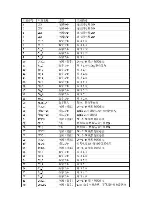

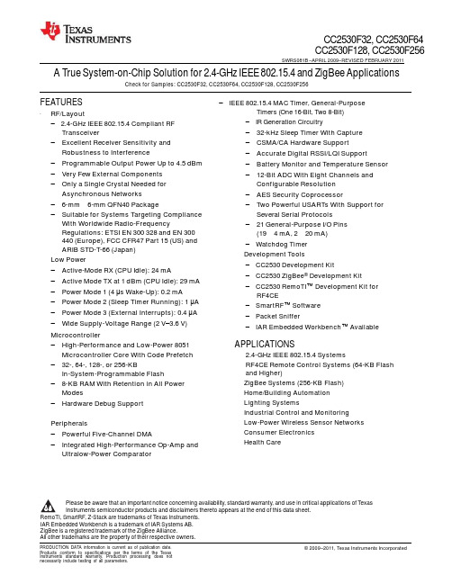
·RF/LayoutCC2530F32,CC2530F64CC2530F128,CC2530F256 SWRS081B–APRIL 2009–REVISED FEBRUARY 2011A True System-on-Chip Solution for2.4-GHz IEEE802.15.4and ZigBee ApplicationsCheck for Samples:CC2530F32,CC2530F64,CC2530F128,CC2530F256FEATURES–IEEE802.15.4MAC Timer,General-Purpose2345– 2.4-GHz IEEE802.15.4Compliant RFTimers(One16-Bit,Two8-Bit)–IR Generation CircuitryTransceiver–32-kHz Sleep Timer With Capture–Excellent Receiver Sensitivity and–CSMA/CA Hardware Support Robustness to Interference–Accurate Digital RSSI/LQI Support–Programmable Output Power Up to4.5dBm–Battery Monitor and Temperature Sensor –Very Few External Components–12-Bit ADC With Eight Channels and–Only a Single Crystal Needed for Configurable Resolution Asynchronous Networks–AES Security Coprocessor–6-mm×6-mm QFN40Package–Two Powerful USARTs With Support for –Suitable for Systems Targeting Compliance Several Serial Protocols With Worldwide Radio-Frequency–21General-Purpose I/O PinsRegulations:ETSI EN300328and EN300(19×4mA,2×20mA)440(Europe),FCC CFR47Part15(US)andARIB STD-T-66(Japan)·Low Power–Active-Mode RX(CPU Idle):24mA–Active Mode TX at1dBm(CPU Idle):29mA –Power Mode1(4μs Wake-Up):0.2mA–Power Mode2(Sleep Timer Running):1μA –Power Mode3(External Interrupts):0.4μA –Wide Supply-Voltage Range(2V–3.6V)–Watchdog Timer·Development Tools–CC2530Development Kit–CC2530ZigBee®Development Kit–CC2530RemoTI™Development Kit for RF4CE–SmartRF™Software–Packet Sniffer–IAR Embedded Workbench™Available·Microcontroller–High-Performance and Low-Power8051APPLICATIONSMicrocontroller Core With Code Prefetch· 2.4-GHz IEEE802.15.4Systems –32-,64-,128-,or256-KB·RF4CE Remote Control Systems(64-KB FlashIn-System-Programmable Flash–8-KB RAM With Retention in All Power Modes–Hardware Debug Support·Peripherals–Powerful Five-Channel DMA–Integrated High-Performance Op-Amp andand Higher)·ZigBee Systems(256-KB Flash)·Home/Building Automation ·Lighting Systems·Industrial Control and Monitoring ·Low-Power Wireless Sensor Networks ·Consumer Electronics·Health CareUltralow-Power ComparatorPlease be aware that an important notice concerning availability,standard warranty,and use in critical applications of Texas Instruments semiconductor products and disclaimers thereto appears at the end of this data sheet.RemoTI,SmartRF,Z-Stack are trademarks of Texas Instruments.IAR Embedded Workbench is a trademark of IAR Systems AB.ZigBee is a registered trademark of the ZigBee Alliance.All other trademarks are the property of their respective owners.CC2530F32,CC2530F64CC2530F128,CC2530F256SWRS081B–APRIL 2009–REVISED FEBRUARY 2011DESCRIPTIONThe CC2530is a true system-on-chip(SoC)solution for IEEE802.15.4,Zigbee and RF4CE applications.Itenables robust network nodes to be built with very low total bill-of-material costs.The CC2530combines theexcellent performance of a leading RF transceiver with an industry-standard enhanced8051MCU,in-system programmable flash memory,8-KB RAM,and many other powerful features.The CC2530comes in four differentflash versions:CC2530F32/64/128/256,with32/64/128/256KB of flash memory,respectively.The CC2530hasvarious operating modes,making it highly suited for systems where ultralow power consumption is required. Short transition times between operating modes further ensure low energy consumption.Combined with the industry-leading and golden-unit-status ZigBee protocol stack(Z-Stack™)from Texas Instruments,the CC2530F256provides a robust and complete ZigBee solution.Combined with the golden-unit-status RemoTI stack from Texas Instruments,the CC2530F64and higher providea robust and complete ZigBee RF4CE remote-control solution.FIFOandFRAMECONTROLSYNTHCC2530F32,CC2530F64CC2530F128,CC2530F256SWRS081B–APRIL 2009–REVISED FEBRUARY 2011 RESET_NXOSC_Q2RESET WATCHDOG TIMER32-MHzON-CHIP VOLTAGEREGULATORPOWER-ON RESETVDD(2V–3.6V)DCOUPLXOSC_Q1CRYSTAL OSC CLOCK MUX BROWN OUTandP2_4P2_332.768-kHzCRYSTAL OSCCALIBRATIONSLEEP TIMERP2_2P2_1DEBUGINTERFACEHIGH-SPEEDRC-OSC32-kHzRC-OSC POWER MANAGEMENT CONTROLLERP2_0P1_7P1_6P1_5P1_48051CPUCOREMEMORY8-KB SRAMP1_3P1_2P1_1P1_0P0_7P0_6ARBITER32/64/128/256-KBFLASHDMAIRQ CTRL FLASH CTRLP0_5P0_4P0_3P0_2P0_1P0_0ANALOGCOMPARATOROP-AMP12-BITADCAESENCRYPTIONANDDECRYPTIONRADIO REGISTERSCSMA/CA STROBE PROCESSORRADIO DATA INTERFACEDEMODULATORMODULATORAND AGCUSART0USART1TIMER1(16-Bit)TIMER2(IEEE802.15.4MAC TIMER)TIMER3(8-Bit)RECEIVECHAINRF_P RF_NTRANSMITCHAINDIGITALANALOGMIXEDTIMER4(8-Bit)B0301-02This integrated circuit can be damaged by ESD.Texas Instruments recommends that all integrated circuits be handled with appropriate precautions.Failure to observe proper handling and installation procedures can cause damage.ESD damage can range from subtle performance degradation to complete device failure.Precision integrated circuits may be more susceptible to damage because very small parametric changes could cause the device not to meet its published specifications.CC2530F32, CC2530F64 CC2530F128, CC2530F256SWRS081B –APRIL 2009–REVISED FEBRUARY 2011ABSOLUTE MAXIMUM RATINGS (1)(1)Stresses beyond those listed under Absolute Maximum Ratings may cause permanent damage to the device. These are stress ratings only, and functional operation of the device at these or any other conditions beyond those indicatedunder Recommended Operating Conditions is not implied. Exposure to absolute-maximum-rated conditions for extended periods may affect device reliability. (2) CAUTION: ESD sensitive device. Precaution should be usedwhen handling the device in order to prevent permanent damage.ELECTRICAL CHARACTERISTICSMeasured on Texas Instruments CC2530 EM reference design with T A = 25°C and VDD = 3 V, unless otherwise noted. Boldface limits apply over the entire operating range, T A = –40°C to 125°C, VDD = 2 V to 3.6 V, and f c = 2394 MHz to (1)Normal flash access means that the code used exceeds the cache storage, so cache misses happen frequently.GENERAL CHARACTERISTICSCC2530F32,CC2530F64CC2530F128,CC2530F256SWRS081B–APRIL 2009–REVISED FEBRUARY 2011 GENERAL CHARACTERISTICS(continued)CC2530F32,CC2530F64CC2530F128,CC2530F256SWRS081B–APRIL 2009–REVISED FEBRUARY 2011RF RECEIVE SECTIONMeasured on Texas Instruments CC2530EM reference design with T A=25°C,VDD=3V,and f c=2440MHz,unless otherwise noted.Boldface limits apply over the entire operating range,T A=–40°C to125°C,VDD=2V to3.6V,and f c=2394MHz to(1)Difference between center frequency of the received RF signal and local oscillator frequency.(2)Difference between incoming symbol rate and the internally generated symbol rateCC2530F32,CC2530F64CC2530F128,CC2530F256SWRS081B–APRIL 2009–REVISED FEBRUARY 2011RF TRANSMIT SECTIONMeasured on Texas Instruments CC2530EM reference design with T A=25°C,VDD=3V and f c=2440MHz,unlessotherwise noted.Boldface limits apply over the entire operating range,T A=–40°C to125°C,VDD=2V to3.6V and f c=2394MHz to2507(1)Texas Instruments CC2530EM reference design is suitable for systems targeting compliance with EN300328,EN300440,FCCCFR47Part15and ARIB STD-T-66.(2)Margins for passing conducted requirements at the third harmonic can be improved by using a simple band-pass filter connectedbetween matching network and RF connector(1.8pF in parallel with1.6nH);this filter must be connected to a good RF ground.(3)Margins for passing FCC requirements at2483.5MHz and above when transmitting at2480MHz can be improved by using a loweroutput-power setting or having less than100%duty cycle.CC2530F32,CC2530F64CC2530F128,CC2530F256SWRS081B–APRIL 2009–REVISED FEBRUARY 201132-MHz CRYSTAL OSCILLATOR(1)Including aging and temperature dependency,as specified by[1]32.768-kHz CRYSTAL OSCILLATOR(1)Including aging and temperature dependency,as specified by[1]32-kHz RC OSCILLATOR(1)The calibrated32-kHz RC oscillator frequency is the32-MHz XTAL frequency divided by977.(2)Frequency drift when temperature changes after calibration(3)Frequency drift when supply voltage changes after calibration(4)When the32-kHz RC oscillator is enabled,it is calibrated when a switch from the16-MHz RC oscillator to the32-MHz crystal oscillatoris performed while SLEEPCMD.OSC32K_CALDIS is0.CC2530F32, CC2530F64 CC2530F128, CC2530F256SWRS081B –APRIL 2009–REVISED FEBRUARY 201116-MHz RC OSCILLATOR(1)The calibrated 16-MHz RC oscillator frequency is the 32-MHz XTAL frequency divided by 2. (2) When the 16-MHz RC oscillator is enabled, it is calibrated when a switch from the 16-MHz RC oscillator to the 32-MHz crystal oscillatoris performed while SLEEPCMD.OSC_PD is set to 0.RSSI/CCA CHARACTERISTICS(1) Real RSSI = Register value – offsetFREQEST CHARACTERISTICS(1)Real FREQEST = Register value – offsetFREQUENCY SYNTHESIZER CHARACTERISTICS Measured on Texas Instruments CC2530 EM reference design with T A = 25°C, VDD = 3 V and f c = 2440 MHz, unlessANALOG TEMPERATURE SENSORCC2530F32,CC2530F64CC2530F128,CC2530F256 SWRS081B–APRIL 2009–REVISED FEBRUARY 2011 OP-AMP CHARACTERISTICSCOMPARATOR CHARACTERISTICSCC2530F32,CC2530F64CC2530F128,CC2530F256SWRS081B–APRIL 2009–REVISED FEBRUARY 2011 ADC CHARACTERISTICS(1)Measured with300-Hz sine-wave input and VDD as reference.CC2530F32,CC2530F64CC2530F128,CC2530F256SWRS081B–APRIL 2009–REVISED FEBRUARY 2011CONTROL INPUT AC CHARACTERISTICSPx.nFigure1.Control Input AC CharacteristicsCC2530F32,CC2530F64CC2530F128,CC2530F256SWRS081B–APRIL 2009–REVISED FEBRUARY 2011SPI AC CHARACTERISTICSSCKSSNMOSIMISOT0478-01Figure2.SPI Master AC CharacteristicsCC2530F32,CC2530F64CC2530F128,CC2530F256SWRS081B–APRIL 2009–REVISED FEBRUARY 2011SCKSSNMISOMOSIT0479-01Figure3.SPI Slave AC Characteristics万联芯城专为终端研发生产企业提供一站式的电子元器件配单服务,所售电子元器件均为原装现货库存,产品质量优秀,价格优势明显,万联芯城拥有30年配单经验,为广大客户解决了生产需求,节省了采购成本。

CC2530APK 使用说明ES Technology 2013年6月10号版本:V1.01模块介绍CC2530APK Z IGBEE模块使用1.5dB的贴片陶瓷天线,在小体积的同时实现远距离的无线通信,并可以实现超低功耗大规模组网,模块的主要参数如下表:模块特点:1.板子尺寸小,采用标准的2.54mm间距插针设计,方便连接和开发;2.功耗低,传输距离远,休眠模式功耗只有0.03uA;3.板子所有IO引出并在板子背面标注引脚定义,方便使用;4.板载电源LED显示,可以指示模块是否连接电源;5.板载多达8个电源滤波电容,供电稳定可靠;6.可以和本店铺的ZigBee开发底板配合使用。
●外形尺寸:●引脚定义:引脚定义图引脚定义(正面放置)注意:1.电源正负极不能接反,否则会烧坏芯片。
2.电源电压VCC输入范围2.5V-3.6V。
2模块原理图模块原理图请参考资料提供的PDF原理图文档。
3模块连接说明本店铺提供转接板,可以直接和转接板相连,变成直插模块,然后和我们店铺的底板相连,方便开发,如下图所示:CC2530APK专用转接板CC2530APK焊接在转接板上与本店铺ZigBee开发底板相连如下图所示:本店铺的的ZigBee开发底板如下图所示。
开发底板的主要硬件有:1.板载USB转串口芯片PL2303,直接插上USB就可以实现和电脑通信,无需外加USB转串口线;2.板载3个3色LED和3个按键,方便用户调试;3.所有IO口全部引出,并在板子上清楚标明,使用非常方便;4.集成12864的液晶接口,插上液晶后,可以实现各种参数的显示;5.可以选择USB电源供电或者外置电池供电,板载两种电源接口;6.有电源开关和编程接口。
易思ZigBee开发底板和电脑连接如下图所示:模块使用USB 线和电脑相连并安装PL2303驱动,即可以实现电脑与无线模块进行通信,通信的界面如下图所示:易思的ZigBee 最小模块可以和其他单片机进行连接,使用串口实现其他单片机与CC2530模块进行通信,只要连接4根线,连接方法如下:单片机 CC2530 模块单片机与CC2530模块连接图程序上,使用串口通信代码,设置好合适的波特率就可以实现两个单片机之VCC单片机的 RX 引脚 单片机的 TX 引脚 单片机的 GND 引脚VCC (2.5V-3.3V )CC2530的 RX 引脚(P02) CC2530的 TX 引脚(P03) CC2530的 GND 引脚(GND )间进行通信。

基于ZigBee技术的温湿度远程监测系统设计学生:陈园(指导老师:吴琰)(淮南师范学院电子工程学院)摘要: 针对目前温室大棚农作物大面积种植,迫切需要科学的方法进行智能远程监测的研究现状,设计出一套温湿度远程监测系统。
该系统是有多个采集终端和一个协调控制器组成。
多个终端分别放置不同的大棚内进行实时采集数据,协调控制器的作用就是将多个采集终端通过无线传输过来的的数据进行分析并和PC机连接。
PC机上运行上位机软件实时的监测各大棚的温湿度信息。
多个终端和协调控制器均采用TI公司新一代CC2530芯片;温湿度传感器采用市场上比较流行的DHT11;无线传输采用ZigBee协议;上位机软件采用labVIEW编写,并通过RS-232与协调控制器连接通信。
通过实物测试了ZigBee无线传输的稳定可靠性,丢包率在误差范围内。
温湿度采集有0.5s延时时间,满足实时性要求。
关键词:终端;协调控制器;DHT11;CC2530;ZigBee;上位机Design of Remote Monitoring System for Temperature andHumidity based on ZigBee TechnologyStudent: Chen Yuan(Faculty Adviser:Wu Yan)(college of electronic engineering, Huainan Normal University)Abstract:According to the current situation of the research on the intelligent remote monitoring of greenhouse crops, the research status of intelligent remotemonitoring is urgently needed, and a set of remote monitoring system fortemperature and humidity is designed. The system is composed of a plurality ofacquisition terminals and a coordinated controller. Multiple terminals are placed indifferent greenhouses for real-time collection of data, the role of the coordinationcontroller is to collect more than one collection terminal through wireless datatransmission over the data analysis and PC machine connection. Temperature andhumidity information operation software of PC real-time monitoring of thegreenhouse on PC. A plurality of terminals and a coordinated controller are used ina new generation of CC2530 chip of TI company; temperature and humidity sensorused on the market more popular DHT11; wireless transmission based on ZigBeeprotocol; PC software using LabVIEW, and connected with the communicationthrough the RS-232 and coordination controller. The reliability of ZigBee wirelesstransmission stability test through the physical, the packet loss rate is in the rangeof error. Temperature and humidity acquisition 0.5s time delay, meet the real-timerequirements.Keywords:Terminal; coordination controller; DHT11;CC2530; ZigBee; host computer1. 绪论1.1 设计背景和研究意义现如今我国已经成为世界第一粮食生产大国,据有关统计说明,我国农作物设施栽培面积已经超过210万hm2。
一.CC2530控制外设的基本方法(通用I/O口)CC2530的I/O控制口一共有21个,分成3组,分别是P0、P1和P2;由上面的对照表可以看出LED1所对应的I/O口为P1_0,LED2所对应的I/O口为P1_1,LED3所对应的I/O口为P1_4,LED4所对应的I/O为P0_1。
相对应的常用SFR有:P1DIR(P1方向寄存器,P0DIR同理):0:输入1:输出P0SEL(P1SEL相同):各个I/O口的功能选择,0为普通I/O功能,1为外设功能寄存器的设置:将控制寄存器的某一位置1:例:P1DIR |= 0X02;解释:”|=“表示按位或运算,0X02为十六进制数,转换成二进制数为0000 0010,若P1DIR原来的值为0011 0000,或运算后P1DIR的值为0011 0010。
根据上面给出的取值表可知,按位与运算后P1_1的方向改为输出,其他I/O口方向保持不变。
将控制寄存器某一位清0:例:P1DIR &= ~0X02;解释:”&=“表示按位与运算,”~“运算符表示取反,0X02为0000 0010,即~0X02为1111 1101。
若P1DIR原来的值为0011 0010,与运算后P1DIR的值为0011 0000。
二.通过中断控制LED,如何捕获一个外部中断和CC2530捕获外部中断后的处理流程D5为USB D+中断状态标志,当D+线有一个中断请求未决时设置该标志,用于检测USB挂起状态下的USB恢复事件。
当USB控制器没有挂起时不设置该标志。
波特率由U0GCR中的低5位和U0BAUD决定,例如:U0GCR |= 9;U0BAUD |= 59;以上代码将波特率设为19200。
五.系统电源管理,外部中断睡眠唤醒PCON(0x87) Bit0. 系统电源模式控制寄存器,置1将强制系统进入SLEEPCMD所指定的电源模式,所有中断信号都可以清除此置位。
SLEEPCMD(0xBE) Bit1:Bit0 系统电源模式设定:00 全功能模式01:PM1 10:PM2 11:PM3系统电源管理(工作方式如下):1. 全功能模式,高频晶振(16M 或者 32M )和低频晶振(32.768K RCOSC/XOSC )全部工作, 数字处理模块正常工作。